ESP RENAULT SCENIC 2010 J95 / 3.G Petrol Injection S3000 Injection Repair Manual
[x] Cancel search | Manufacturer: RENAULT, Model Year: 2010, Model line: SCENIC, Model: RENAULT SCENIC 2010 J95 / 3.GPages: 230, PDF Size: 0.92 MB
Page 111 of 230
PETROL INJECTION
Fault finding - Interpretation of faults
17B
17B-111
PETROL INJECTION
Fault finding - Interpretation of faults
17B
17B-111V9 MR-372-J84-17B050$423.mif
S3000 Injection
Program No.: AD
Vdiag No.: 4C / 54
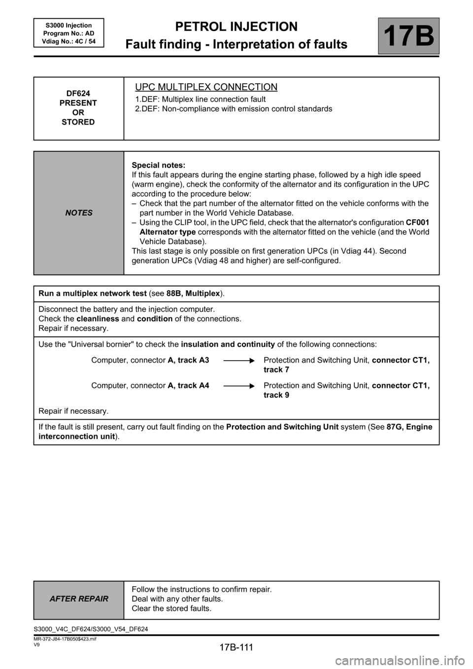
DF624
PRESENT
OR
STOREDUPC MULTIPLEX CONNECTION
1.DEF: Multiplex line connection fault
2.DEF: Non-compliance with emission control standards
NOTESSpecial notes:
If this fault appears during the engine starting phase, followed by a high idle speed
(warm engine), check the conformity of the alternator and its configuration in the UPC
according to the procedure below:
– Check that the part number of the alternator fitted on the vehicle conforms with the
part number in the World Vehicle Database.
– Using the CLIP tool, in the UPC field, check that the alternator's configuration CF001
Alternator type corresponds with the alternator fitted on the vehicle (and the World
Vehicle Database).
This last stage is only possible on first generation UPCs (in Vdiag 44). Second
generation UPCs (Vdiag 48 and higher) are self-configured.
Run a multiplex network test (see88B, Multiplex).
Disconnect the battery and the injection computer.
Check the cleanliness and condition of the connections.
Repair if necessary.
Use the "Universal bornier" to check the insulation and continuity of the following connections:
Computer, connectorA, track A3Protection and Switching Unit, connector CT1,
track 7
Computer, connectorA, track A4Protection and Switching Unit, connector CT1,
track 9
Repair if necessary.
If the fault is still present, carry out fault finding on the Protection and Switching Unit system (See87G, Engine
interconnection unit).
AFTER REPAIRFollow the instructions to confirm repair.
Deal with any other faults.
Clear the stored faults.
S3000_V4C_DF624/S3000_V54_DF624
Page 112 of 230
PETROL INJECTION
Fault finding - Interpretation of faults
17B
17B-112V9 MR-372-J84-17B050$423.mif
S3000 Injection
Program No.: AD
Vdiag No.: 4C / 54
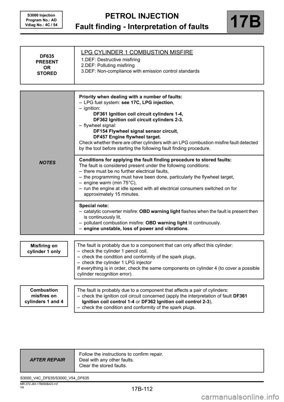
DF635
PRESENT
OR
STOREDLPG CYLINDER 1 COMBUSTION MISFIRE
1.DEF: Destructive misfiring
2.DEF: Polluting misfiring
3.DEF: Non-compliance with emission control standards
NOTESPriority when dealing with a number of faults:
– LPG fuel system: see 17C, LPG injection,
– ignition:
DF361 Ignition coil circuit cylinders 1-4,
DF362 Ignition coil circuit cylinders 2-3.
– flywheel signal:
DF154 Flywheel signal sensor circuit,
DF457 Engine flywheel target.
Check whether there are other cylinders with an LPG combustion misfire fault detected
by the tool before starting the following fault finding procedure.
Conditions for applying the fault finding procedure to stored faults:
The fault is considered present under the following conditions:
– there must be no further electrical faults,
– the programming must have been done, particularly the flywheel target,
– engine warm (min 75°C),
– run the engine at idle speed with all electrical consumers switched on for
approximately 15 minutes.
Special note:
– catalytic converter misfire: OBD warning light flashes when the fault is present then
is continuously lit,
– pollutant combustion misfire: OBD warning light lit continuously.
–engine unstable, loss of power and vibrations.
Misfiring on
cylinder 1 only
Combustion
misfires on
cylinders 1 and 4
The fault is probably due to a component that can only affect this cylinder:
– check the cylinder 1 pencil coil,
– check the condition and conformity of the spark plugs,
– check the cylinder 1 LPG injector
If everything is in order, check the same components on cylinder 4 (to cover a possible
cylinder recognition error).
The fault is probably due to a component that affects a pair of cylinders:
– check the ignition coil circuit concerned (apply the interpretation of fault DF361
Ignition coil control 1-4 or DF362 Ignition coil control 2-3),
– check the condition and conformity of the spark plugs.
AFTER REPAIRFollow the instructions to confirm repair.
Deal with any other faults.
Clear the stored faults.
S3000_V4C_DF635/S3000_V54_DF635
Page 113 of 230
PETROL INJECTION
Fault finding - Interpretation of faults
17B
17B-113V9 MR-372-J84-17B050$423.mif
S3000 Injection
Program No.: AD
Vdiag No.: 4C / 54
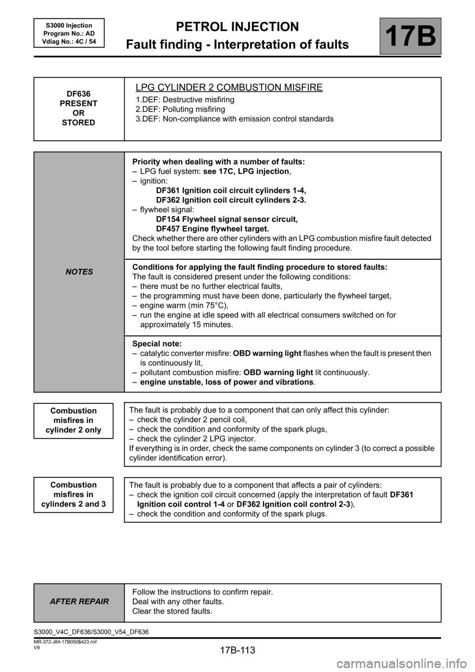
DF636
PRESENT
OR
STOREDLPG CYLINDER 2 COMBUSTION MISFIRE
1.DEF: Destructive misfiring
2.DEF: Polluting misfiring
3.DEF: Non-compliance with emission control standards
NOTESPriority when dealing with a number of faults:
– LPG fuel system: see 17C, LPG injection,
– ignition:
DF361 Ignition coil circuit cylinders 1-4,
DF362 Ignition coil circuit cylinders 2-3.
– flywheel signal:
DF154 Flywheel signal sensor circuit,
DF457 Engine flywheel target.
Check whether there are other cylinders with an LPG combustion misfire fault detected
by the tool before starting the following fault finding procedure.
Conditions for applying the fault finding procedure to stored faults:
The fault is considered present under the following conditions:
– there must be no further electrical faults,
– the programming must have been done, particularly the flywheel target,
– engine warm (min 75°C),
– run the engine at idle speed with all electrical consumers switched on for
approximately 15 minutes.
Special note:
– catalytic converter misfire: OBD warning light flashes when the fault is present then
is continuously lit,
– pollutant combustion misfire: OBD warning light lit continuously.
–engine unstable, loss of power and vibrations.
Combustion
misfires in
cylinder 2 only
Combustion
misfires in
cylinders 2 and 3
The fault is probably due to a component that can only affect this cylinder:
– check the cylinder 2 pencil coil,
– check the condition and conformity of the spark plugs,
– check the cylinder 2 LPG injector.
If everything is in order, check the same components on cylinder 3 (to correct a possible
cylinder identification error).
The fault is probably due to a component that affects a pair of cylinders:
– check the ignition coil circuit concerned (apply the interpretation of fault DF361
Ignition coil control 1-4 or DF362 Ignition coil control 2-3),
– check the condition and conformity of the spark plugs.
AFTER REPAIRFollow the instructions to confirm repair.
Deal with any other faults.
Clear the stored faults.
S3000_V4C_DF636/S3000_V54_DF636
Page 114 of 230
PETROL INJECTION
Fault finding - Interpretation of faults
17B
17B-114V9 MR-372-J84-17B050$423.mif
S3000 Injection
Program No.: AD
Vdiag No.: 4C / 54
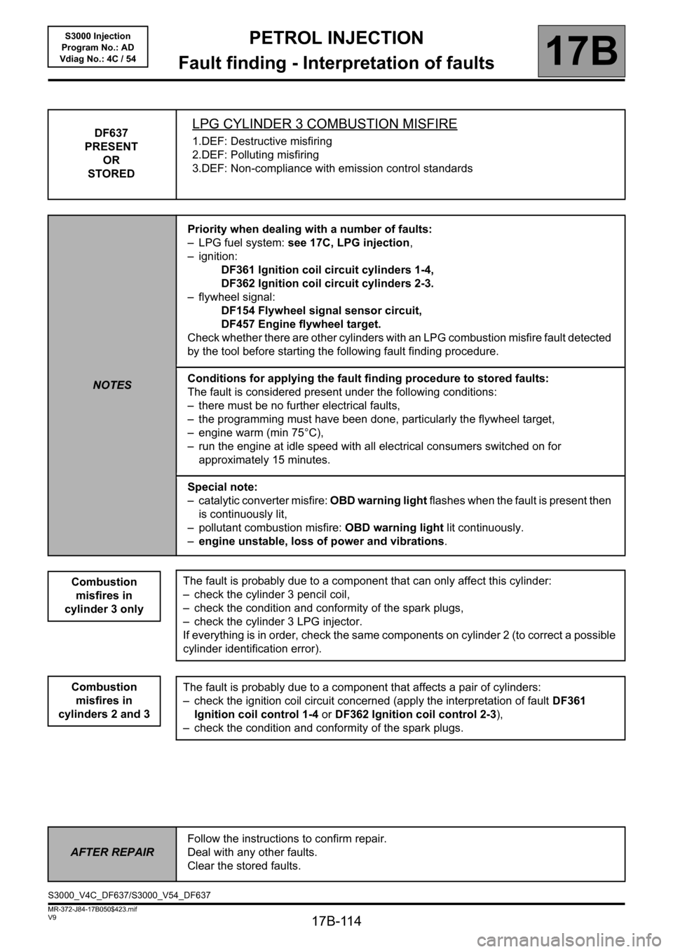
DF637
PRESENT
OR
STOREDLPG CYLINDER 3 COMBUSTION MISFIRE
1.DEF: Destructive misfiring
2.DEF: Polluting misfiring
3.DEF: Non-compliance with emission control standards
NOTESPriority when dealing with a number of faults:
– LPG fuel system: see 17C, LPG injection,
– ignition:
DF361 Ignition coil circuit cylinders 1-4,
DF362 Ignition coil circuit cylinders 2-3.
– flywheel signal:
DF154 Flywheel signal sensor circuit,
DF457 Engine flywheel target.
Check whether there are other cylinders with an LPG combustion misfire fault detected
by the tool before starting the following fault finding procedure.
Conditions for applying the fault finding procedure to stored faults:
The fault is considered present under the following conditions:
– there must be no further electrical faults,
– the programming must have been done, particularly the flywheel target,
– engine warm (min 75°C),
– run the engine at idle speed with all electrical consumers switched on for
approximately 15 minutes.
Special note:
– catalytic converter misfire: OBD warning light flashes when the fault is present then
is continuously lit,
– pollutant combustion misfire: OBD warning light lit continuously.
–engine unstable, loss of power and vibrations.
Combustion
misfires in
cylinder 3 only
Combustion
misfires in
cylinders 2 and 3
The fault is probably due to a component that can only affect this cylinder:
– check the cylinder 3 pencil coil,
– check the condition and conformity of the spark plugs,
– check the cylinder 3 LPG injector.
If everything is in order, check the same components on cylinder 2 (to correct a possible
cylinder identification error).
The fault is probably due to a component that affects a pair of cylinders:
– check the ignition coil circuit concerned (apply the interpretation of fault DF361
Ignition coil control 1-4 or DF362 Ignition coil control 2-3),
– check the condition and conformity of the spark plugs.
AFTER REPAIRFollow the instructions to confirm repair.
Deal with any other faults.
Clear the stored faults.
S3000_V4C_DF637/S3000_V54_DF637
Page 115 of 230
PETROL INJECTION
Fault finding - Interpretation of faults
17B
17B-115V9 MR-372-J84-17B050$423.mif
S3000 Injection
Program No.: AD
Vdiag No.: 4C / 54
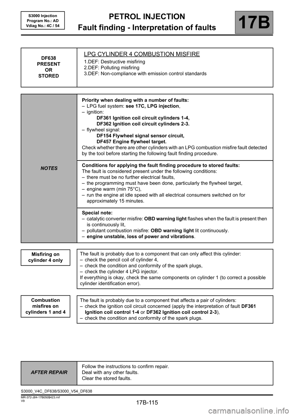
DF638
PRESENT
OR
STOREDLPG CYLINDER 4 COMBUSTION MISFIRE
1.DEF: Destructive misfiring
2.DEF: Polluting misfiring
3.DEF: Non-compliance with emission control standards
NOTESPriority when dealing with a number of faults:
– LPG fuel system: see 17C, LPG injection,
– ignition:
DF361 Ignition coil circuit cylinders 1-4,
DF362 Ignition coil circuit cylinders 2-3.
– flywheel signal:
DF154 Flywheel signal sensor circuit,
DF457 Engine flywheel target.
Check whether there are other cylinders with an LPG combustion misfire fault detected
by the tool before starting the following fault finding procedure.
Conditions for applying the fault finding procedure to stored faults:
The fault is considered present under the following conditions:
– there must be no further electrical faults,
– the programming must have been done, particularly the flywheel target,
– engine warm (min 75°C),
– run the engine at idle speed with all electrical consumers switched on for
approximately 15 minutes.
Special note:
– catalytic converter misfire: OBD warning light flashes when the fault is present then
is continuously lit,
– pollutant combustion misfire: OBD warning light lit continuously.
–engine unstable, loss of power and vibrations.
Misfiring on
cylinder 4 only
Combustion
misfires on
cylinders 1 and 4
The fault is probably due to a component that can only affect this cylinder:
– check the pencil coil of cylinder 4,
– check the condition and conformity of the spark plugs,
– check the cylinder 4 LPG injector.
If everything is okay, check the same components on cylinder 1 (to correct a possible
cylinder identification error).
The fault is probably due to a component that affects a pair of cylinders:
– check the ignition coil circuit concerned (apply the interpretation of fault DF361
Ignition coil control 1-4 or DF362 Ignition coil control 2-3),
– check the condition and conformity of the spark plugs.
AFTER REPAIRFollow the instructions to confirm repair.
Deal with any other faults.
Clear the stored faults.
S3000_V4C_DF638/S3000_V54_DF638
Page 116 of 230
PETROL INJECTION
Fault finding - Interpretation of faults
17B
17B-116
PETROL INJECTION
Fault finding - Interpretation of faults
17B
17B-116V9 MR-372-J84-17B050$423.mif
S3000 Injection
Program No.: AD
Vdiag No.: 4C / 54
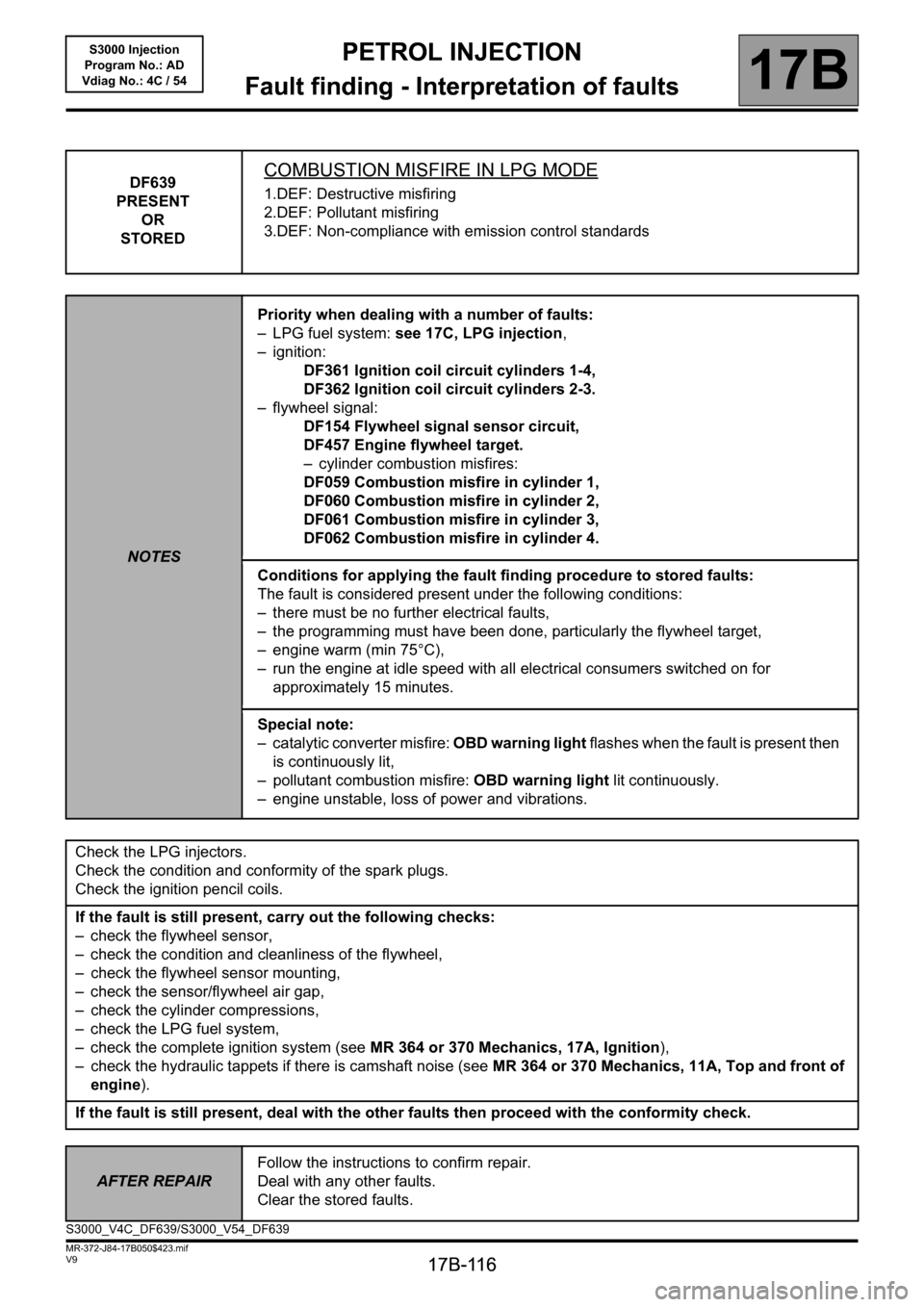
DF639
PRESENT
OR
STOREDCOMBUSTION MISFIRE IN LPG MODE
1.DEF: Destructive misfiring
2.DEF: Pollutant misfiring
3.DEF: Non-compliance with emission control standards
NOTESPriority when dealing with a number of faults:
– LPG fuel system: see 17C, LPG injection,
– ignition:
DF361 Ignition coil circuit cylinders 1-4,
DF362 Ignition coil circuit cylinders 2-3.
– flywheel signal:
DF154 Flywheel signal sensor circuit,
DF457 Engine flywheel target.
– cylinder combustion misfires:
DF059 Combustion misfire in cylinder 1,
DF060 Combustion misfire in cylinder 2,
DF061 Combustion misfire in cylinder 3,
DF062 Combustion misfire in cylinder 4.
Conditions for applying the fault finding procedure to stored faults:
The fault is considered present under the following conditions:
– there must be no further electrical faults,
– the programming must have been done, particularly the flywheel target,
– engine warm (min 75°C),
– run the engine at idle speed with all electrical consumers switched on for
approximately 15 minutes.
Special note:
– catalytic converter misfire: OBD warning light flashes when the fault is present then
is continuously lit,
– pollutant combustion misfire: OBD warning light lit continuously.
– engine unstable, loss of power and vibrations.
Check the LPG injectors.
Check the condition and conformity of the spark plugs.
Check the ignition pencil coils.
If the fault is still present, carry out the following checks:
– check the flywheel sensor,
– check the condition and cleanliness of the flywheel,
– check the flywheel sensor mounting,
– check the sensor/flywheel air gap,
– check the cylinder compressions,
– check the LPG fuel system,
– check the complete ignition system (see MR 364 or 370 Mechanics, 17A, Ignition),
– check the hydraulic tappets if there is camshaft noise (see MR 364 or 370 Mechanics, 11A, Top and front of
engine).
If the fault is still present, deal with the other faults then proceed with the conformity check.
AFTER REPAIRFollow the instructions to confirm repair.
Deal with any other faults.
Clear the stored faults.
S3000_V4C_DF639/S3000_V54_DF639
Page 117 of 230
PETROL INJECTION
Fault finding - Interpretation of faults
17B
17B-117
PETROL INJECTION
Fault finding - Interpretation of faults
17B
17B-117V9 MR-372-J84-17B050$423.mif
S3000 Injection
Program No.: AD
Vdiag No.: 4C / 54
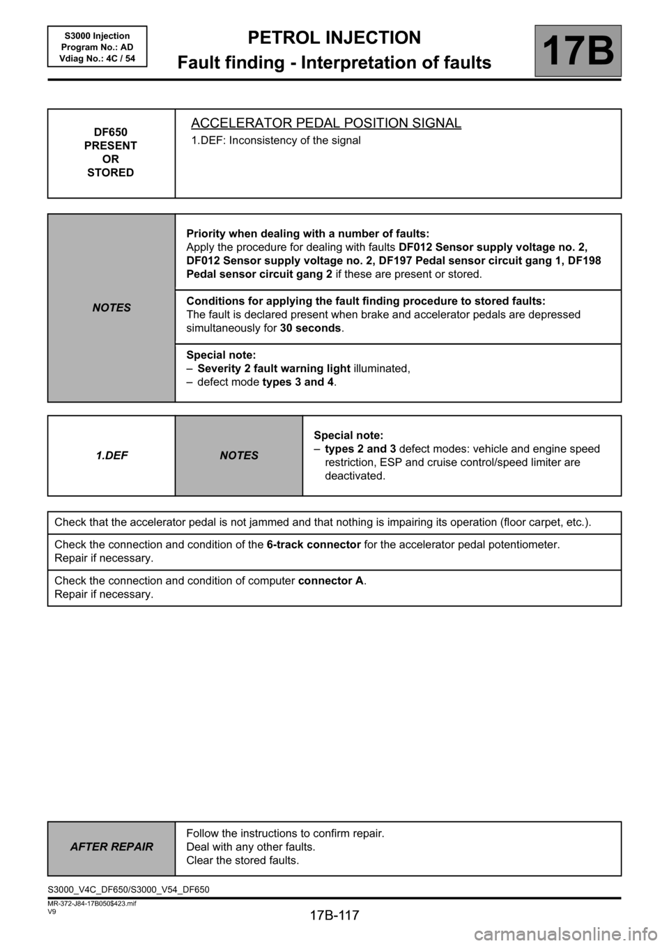
DF650
PRESENT
OR
STOREDACCELERATOR PEDAL POSITION SIGNAL
1.DEF: Inconsistency of the signal
NOTESPriority when dealing with a number of faults:
Apply the procedure for dealing with faults DF012 Sensor supply voltage no. 2,
DF012 Sensor supply voltage no. 2, DF197 Pedal sensor circuit gang 1, DF198
Pedal sensor circuit gang 2 if these are present or stored.
Conditions for applying the fault finding procedure to stored faults:
The fault is declared present when brake and accelerator pedals are depressed
simultaneously for 30 seconds.
Special note:
–Severity 2 fault warning light illuminated,
– defect mode types 3 and 4.
1.DEF
NOTESSpecial note:
–types 2 and 3 defect modes: vehicle and engine speed
restriction, ESP and cruise control/speed limiter are
deactivated.
Check that the accelerator pedal is not jammed and that nothing is impairing its operation (floor carpet, etc.).
Check the connection and condition of the 6-track connector for the accelerator pedal potentiometer.
Repair if necessary.
Check the connection and condition of computer connector A.
Repair if necessary.
AFTER REPAIRFollow the instructions to confirm repair.
Deal with any other faults.
Clear the stored faults.
S3000_V4C_DF650/S3000_V54_DF650
Page 170 of 230
PETROL INJECTION
Fault finding - Interpretation of statuses
17B
17B - 170
PETROL INJECTION
Fault finding - Interpretation of statuses
17B
17B - 170V9 MR-372-J84-17B050$611.mif
S3000 Injection
Program No.: AD
Vdiag No.: 4C / 54PETROL INJECTION
Fault finding - Interpretation of statuses
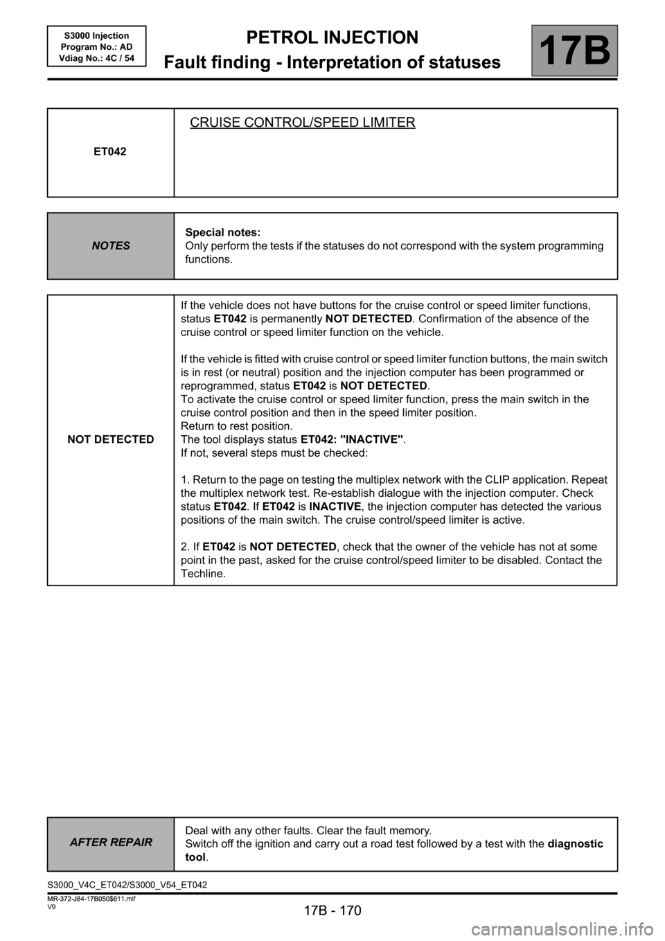
ET042
CRUISE CONTROL/SPEED LIMITER
NOTESSpecial notes:
Only perform the tests if the statuses do not correspond with the system programming
functions.
NOT DETECTEDIf the vehicle does not have buttons for the cruise control or speed limiter functions,
status ET042 is permanently NOT DETECTED. Confirmation of the absence of the
cruise control or speed limiter function on the vehicle.
If the vehicle is fitted with cruise control or speed limiter function buttons, the main switch
is in rest (or neutral) position and the injection computer has been programmed or
reprogrammed, status ET042 is NOT DETECTED.
To activate the cruise control or speed limiter function, press the main switch in the
cruise control position and then in the speed limiter position.
Return to rest position.
The tool displays status ET042: "INACTIVE".
If not, several steps must be checked:
1. Return to the page on testing the multiplex network with the CLIP application. Repeat
the multiplex network test. Re-establish dialogue with the injection computer. Check
status ET042. If ET042 is INACTIVE, the injection computer has detected the various
positions of the main switch. The cruise control/speed limiter is active.
2. If ET042 is NOT DETECTED, check that the owner of the vehicle has not at some
point in the past, asked for the cruise control/speed limiter to be disabled. Contact the
Techline.
AFTER REPAIRDeal with any other faults. Clear the fault memory.
Switch off the ignition and carry out a road test followed by a test with the diagnostic
tool.
S3000_V4C_ET042/S3000_V54_ET042
MR-372-J84-17B050$611.mif
Page 171 of 230
PETROL INJECTION
Fault finding - Interpretation of statuses
17B
17B - 171
PETROL INJECTION
Fault finding - Interpretation of statuses
17B
17B - 171V9 MR-372-J84-17B050$611.mif
S3000 Injection
Program No.: AD
Vdiag No.: 4C / 54
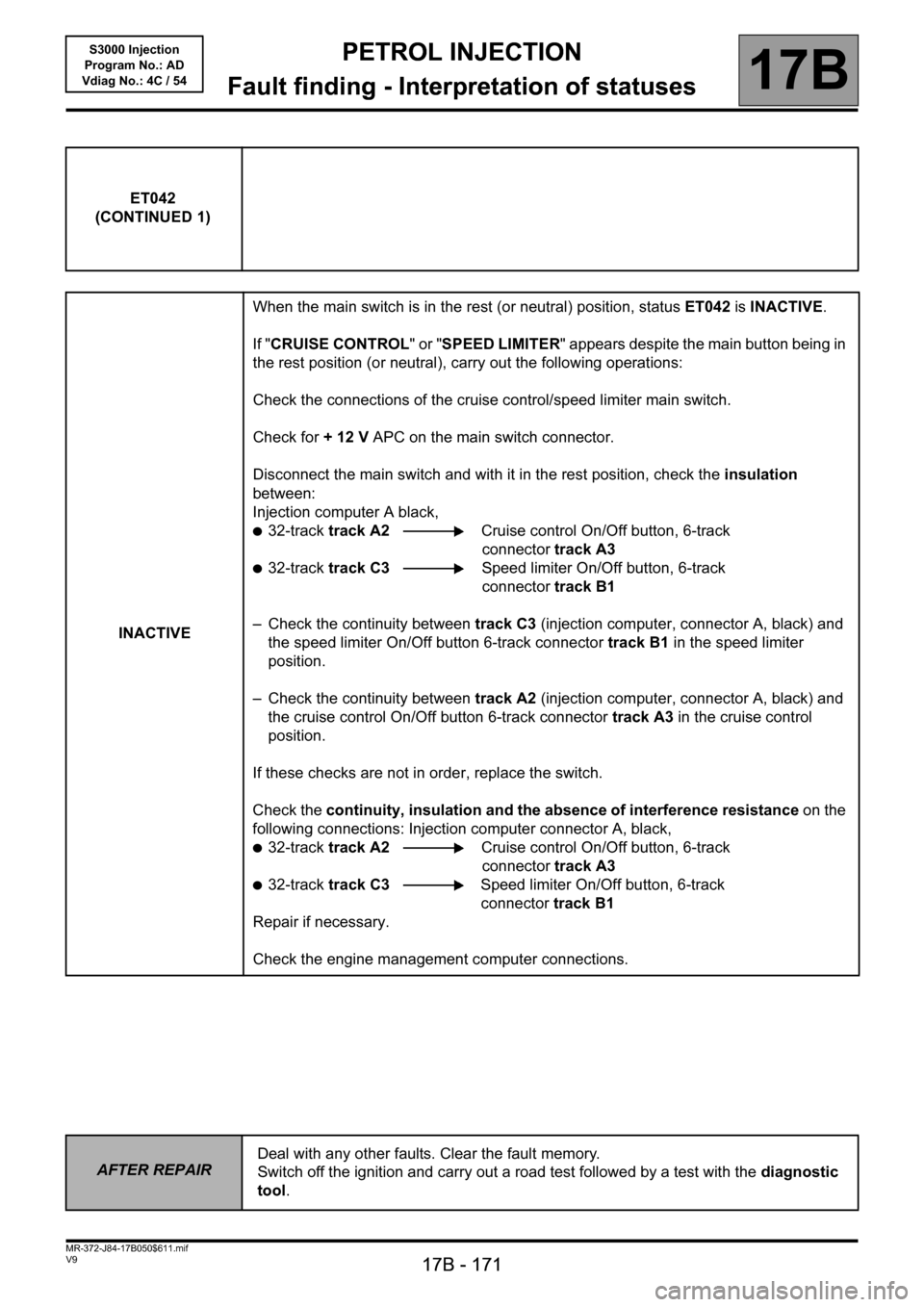
ET042
(CONTINUED 1)
INACTIVEWhen the main switch is in the rest (or neutral) position, status ET042 is INACTIVE.
If "CRUISE CONTROL" or "SPEED LIMITER" appears despite the main button being in
the rest position (or neutral), carry out the following operations:
Check the connections of the cruise control/speed limiter main switch.
Check for + 12 V APC on the main switch connector.
Disconnect the main switch and with it in the rest position, check the insulation
between:
Injection computer A black,
●32-track track A2 Cruise control On/Off button, 6-track
connector track A3
●32-track track C3 Speed limiter On/Off button, 6-track
connector track B1
– Check the continuity between track C3 (injection computer, connector A, black) and
the speed limiter On/Off button 6-track connector track B1 in the speed limiter
position.
– Check the continuity between track A2 (injection computer, connector A, black) and
the cruise control On/Off button 6-track connector track A3 in the cruise control
position.
If these checks are not in order, replace the switch.
Check the continuity, insulation and the absence of interference resistance on the
following connections: Injection computer connector A, black,
●32-track track A2 Cruise control On/Off button, 6-track
connector track A3
●32-track track C3 Speed limiter On/Off button, 6-track
connector track B1
Repair if necessary.
Check the engine management computer connections.
AFTER REPAIRDeal with any other faults. Clear the fault memory.
Switch off the ignition and carry out a road test followed by a test with the diagnostic
tool.
Page 185 of 230
PETROL INJECTION
Fault finding - Interpretation of statuses
17B
17B - 185
PETROL INJECTION
Fault finding - Interpretation of statuses
17B
17B - 185V9 MR-372-J84-17B050$611.mif
S3000 Injection
Program No.: AD
Vdiag No.: 4C / 54
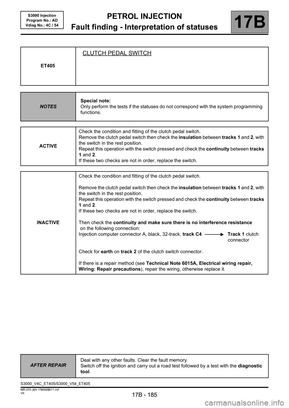
ET405
CLUTCH PEDAL SWITCH
NOTESSpecial note:
Only perform the tests if the statuses do not correspond with the system programming
functions.
ACTIVECheck the condition and fitting of the clutch pedal switch.
Remove the clutch pedal switch then check the insulation between tracks 1 and 2, with
the switch in the rest position.
Repeat this operation with the switch pressed and check the continuity between tracks
1 and 2.
If these two checks are not in order, replace the switch.
INACTIVECheck the condition and fitting of the clutch pedal switch.
Remove the clutch pedal switch then check the insulation between tracks 1 and 2, with
the switch in the rest position.
Repeat this operation with the switch pressed and check the continuity between tracks
1 and 2.
If these two checks are not in order, replace the switch.
Then check the continuity and make sure there is no interference resistance
on the following connection:
Injection computer connector A, black, 32-track, track C4 Track 1 clutch
connector
Check for earth on track 2 of the clutch switch connector.
If there is a repair method (see Technical Note 6015A, Electrical wiring repair,
Wiring: Repair precautions), repair the wiring, otherwise replace it.
AFTER REPAIRDeal with any other faults. Clear the fault memory.
Switch off the ignition and carry out a road test followed by a test with the diagnostic
tool.
S3000_V4C_ET405/S3000_V54_ET405