ESP RENAULT SCENIC 2010 J95 / 3.G Petrol Injection S3000 Injection Owner's Manual
[x] Cancel search | Manufacturer: RENAULT, Model Year: 2010, Model line: SCENIC, Model: RENAULT SCENIC 2010 J95 / 3.GPages: 230, PDF Size: 0.92 MB
Page 55 of 230
PETROL INJECTION
Fault finding - Interpretation of faults
17B
17B-55
PETROL INJECTION
Fault finding - Interpretation of faults
17B
17B-55V9 MR-372-J84-17B050$329.mif
S3000 Injection
Program No.: AD
Vdiag No.: 4C / 54
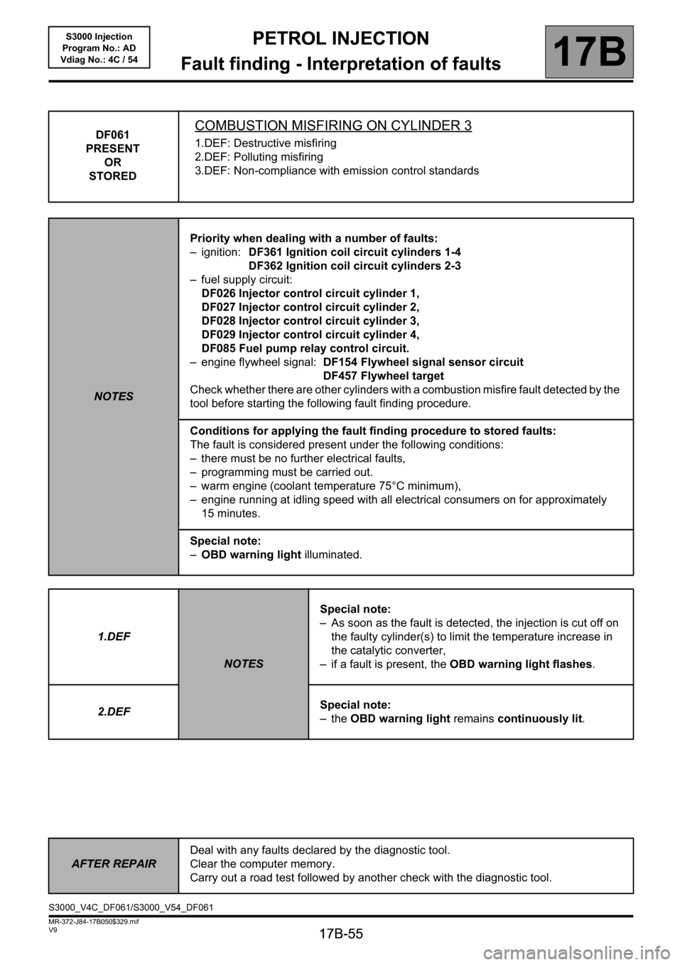
DF061
PRESENT
OR
STOREDCOMBUSTION MISFIRING ON CYLINDER 3
1.DEF: Destructive misfiring
2.DEF: Polluting misfiring
3.DEF: Non-compliance with emission control standards
NOTESPriority when dealing with a number of faults:
– ignition: DF361 Ignition coil circuit cylinders 1-4
DF362 Ignition coil circuit cylinders 2-3
– fuel supply circuit:
DF026 Injector control circuit cylinder 1,
DF027 Injector control circuit cylinder 2,
DF028 Injector control circuit cylinder 3,
DF029 Injector control circuit cylinder 4,
DF085 Fuel pump relay control circuit.
– engine flywheel signal: DF154 Flywheel signal sensor circuit
DF457 Flywheel target
Check whether there are other cylinders with a combustion misfire fault detected by the
tool before starting the following fault finding procedure.
Conditions for applying the fault finding procedure to stored faults:
The fault is considered present under the following conditions:
– there must be no further electrical faults,
– programming must be carried out.
– warm engine (coolant temperature 75°C minimum),
– engine running at idling speed with all electrical consumers on for approximately
15 minutes.
Special note:
–OBD warning light illuminated.
1.DEF
NOTESSpecial note:
– As soon as the fault is detected, the injection is cut off on
the faulty cylinder(s) to limit the temperature increase in
the catalytic converter,
– if a fault is present, the OBD warning light flashes.
2.DEFSpecial note:
–the OBD warning light remains continuously lit.
AFTER REPAIRDeal with any faults declared by the diagnostic tool.
Clear the computer memory.
Carry out a road test followed by another check with the diagnostic tool.
S3000_V4C_DF061/S3000_V54_DF061
Page 57 of 230
PETROL INJECTION
Fault finding - Interpretation of faults
17B
17B-57
PETROL INJECTION
Fault finding - Interpretation of faults
17B
17B-57V9 MR-372-J84-17B050$329.mif
S3000 Injection
Program No.: AD
Vdiag No.: 4C / 54
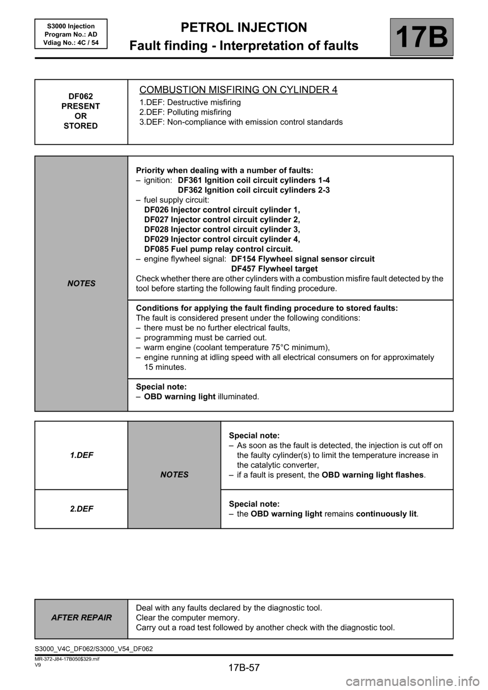
DF062
PRESENT
OR
STOREDCOMBUSTION MISFIRING ON CYLINDER 4
1.DEF: Destructive misfiring
2.DEF: Polluting misfiring
3.DEF: Non-compliance with emission control standards
NOTESPriority when dealing with a number of faults:
– ignition: DF361 Ignition coil circuit cylinders 1-4
DF362 Ignition coil circuit cylinders 2-3
– fuel supply circuit:
DF026 Injector control circuit cylinder 1,
DF027 Injector control circuit cylinder 2,
DF028 Injector control circuit cylinder 3,
DF029 Injector control circuit cylinder 4,
DF085 Fuel pump relay control circuit.
– engine flywheel signal: DF154 Flywheel signal sensor circuit
DF457 Flywheel target
Check whether there are other cylinders with a combustion misfire fault detected by the
tool before starting the following fault finding procedure.
Conditions for applying the fault finding procedure to stored faults:
The fault is considered present under the following conditions:
– there must be no further electrical faults,
– programming must be carried out.
– warm engine (coolant temperature 75°C minimum),
– engine running at idling speed with all electrical consumers on for approximately
15 minutes.
Special note:
–OBD warning light illuminated.
1.DEF
NOTESSpecial note:
– As soon as the fault is detected, the injection is cut off on
the faulty cylinder(s) to limit the temperature increase in
the catalytic converter,
– if a fault is present, the OBD warning light flashes.
2.DEFSpecial note:
–the OBD warning light remains continuously lit.
AFTER REPAIRDeal with any faults declared by the diagnostic tool.
Clear the computer memory.
Carry out a road test followed by another check with the diagnostic tool.
S3000_V4C_DF062/S3000_V54_DF062
Page 59 of 230
PETROL INJECTION
Fault finding - Interpretation of faults
17B
17B-59
PETROL INJECTION
Fault finding - Interpretation of faults
17B
17B-59V9 MR-372-J84-17B050$329.mif
S3000 Injection
Program No.: AD
Vdiag No.: 4C / 54
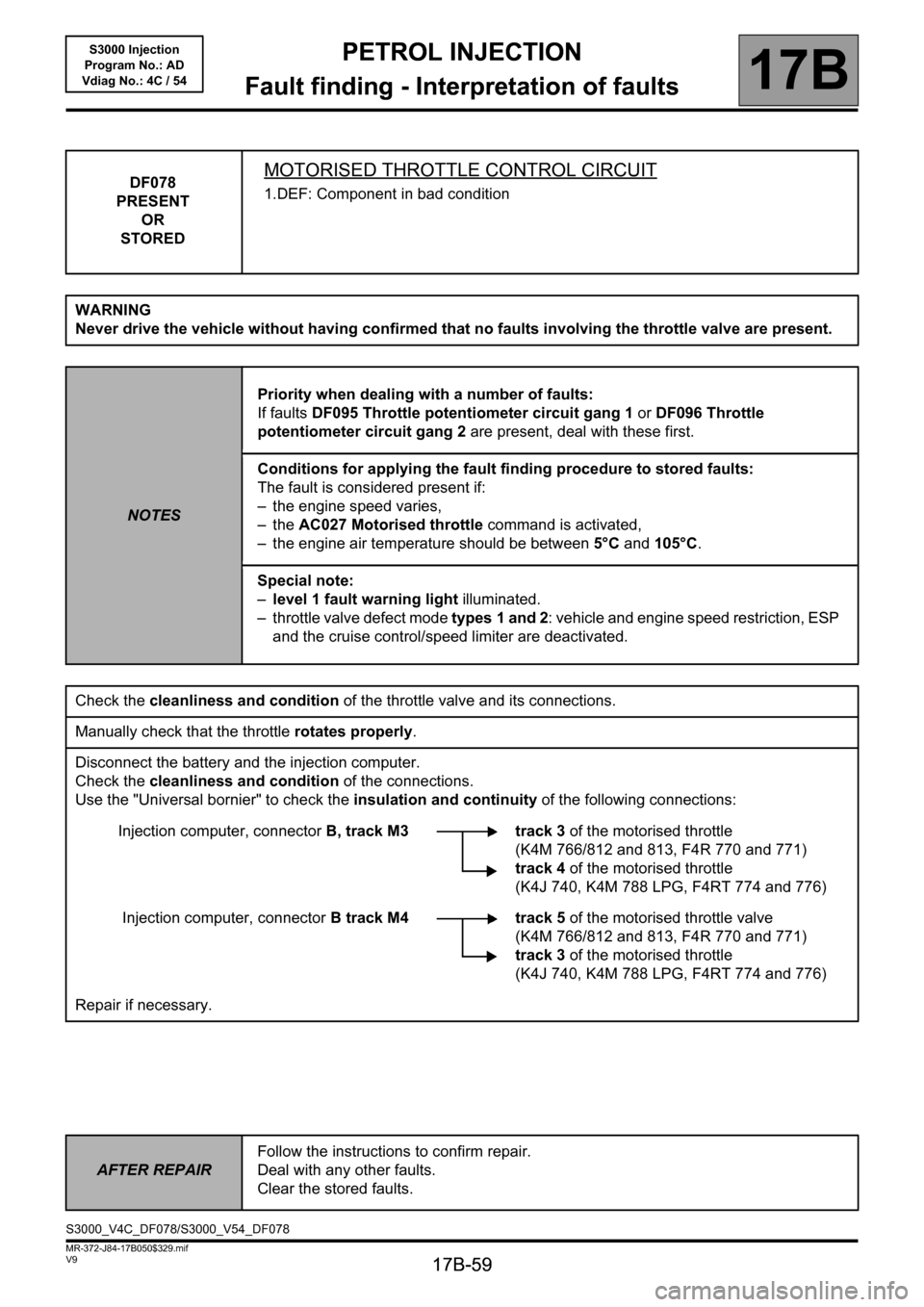
DF078
PRESENT
OR
STOREDMOTORISED THROTTLE CONTROL CIRCUIT
1.DEF: Component in bad condition
WARNING
Never drive the vehicle without having confirmed that no faults involving the throttle valve are present.
NOTESPriority when dealing with a number of faults:
If faults DF095 Throttle potentiometer circuit gang 1 or DF096 Throttle
potentiometer circuit gang 2 are present, deal with these first.
Conditions for applying the fault finding procedure to stored faults:
The fault is considered present if:
– the engine speed varies,
–the AC027 Motorised throttle command is activated,
– the engine air temperature should be between 5°C and 105°C.
Special note:
–level 1 fault warning light illuminated.
– throttle valve defect mode types 1 and 2: vehicle and engine speed restriction, ESP
and the cruise control/speed limiter are deactivated.
Check the cleanliness and condition of the throttle valve and its connections.
Manually check that the throttle rotates properly.
Disconnect the battery and the injection computer.
Check the cleanliness and condition of the connections.
Use the "Universal bornier" to check the insulation and continuity of the following connections:
Injection computer, connectorB, track M3 track 3 of the motorised throttle
(K4M 766/812 and 813, F4R 770 and 771)
track 4of the motorised throttle
(K4J 740, K4M 788 LPG, F4RT 774 and 776)
Injection computer, connectorB track M4 track 5 of the motorised throttle valve
(K4M 766/812 and 813, F4R 770 and 771)
track 3 of the motorised throttle
(K4J 740, K4M 788 LPG, F4RT 774 and 776)
Repair if necessary.
AFTER REPAIRFollow the instructions to confirm repair.
Deal with any other faults.
Clear the stored faults.
S3000_V4C_DF078/S3000_V54_DF078
Page 61 of 230
PETROL INJECTION
Fault finding - Interpretation of faults
17B
17B-61
PETROL INJECTION
Fault finding - Interpretation of faults
17B
17B-61V9 MR-372-J84-17B050$329.mif
S3000 Injection
Program No.: AD
Vdiag No.: 4C / 54
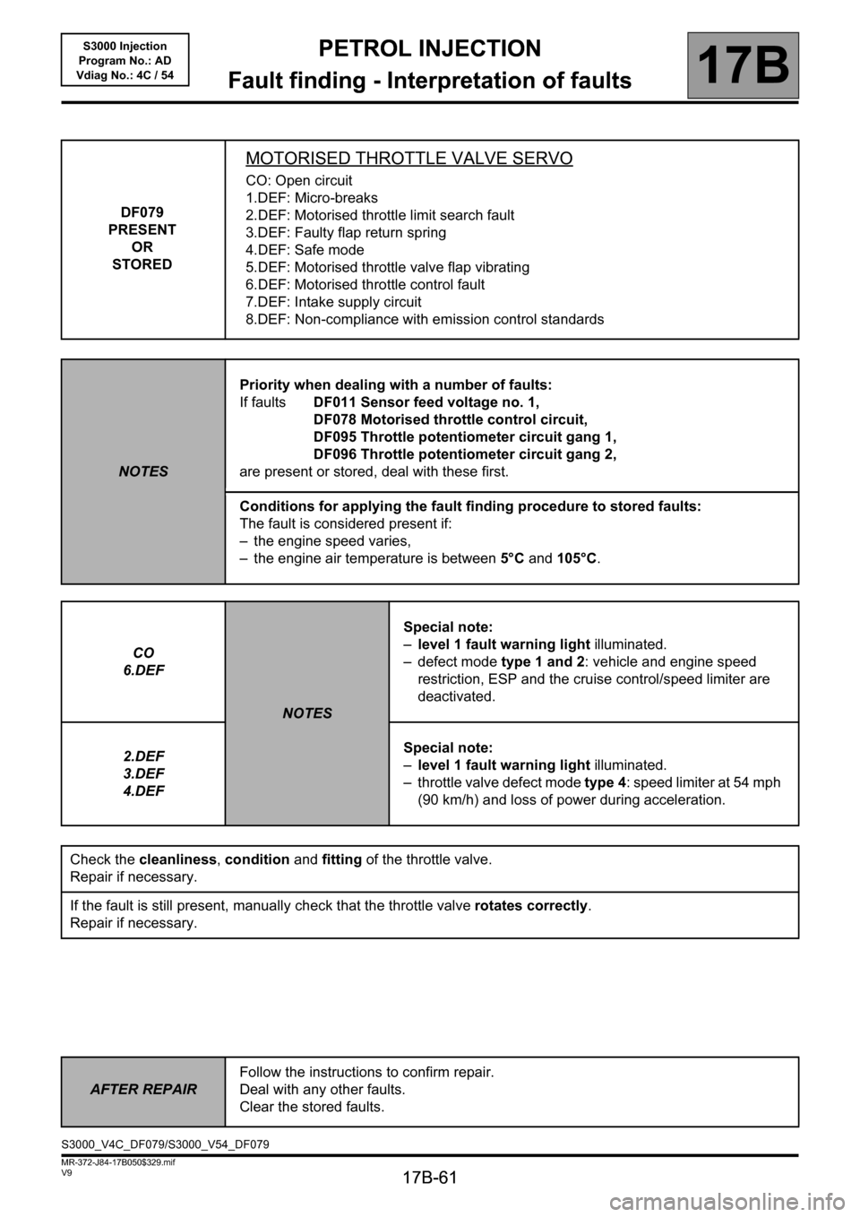
DF079
PRESENT
OR
STORED
MOTORISED THROTTLE VALVE SERVO
CO: Open circuit
1.DEF: Micro-breaks
2.DEF: Motorised throttle limit search fault
3.DEF: Faulty flap return spring
4.DEF: Safe mode
5.DEF: Motorised throttle valve flap vibrating
6.DEF: Motorised throttle control fault
7.DEF: Intake supply circuit
8.DEF: Non-compliance with emission control standards
NOTESPriority when dealing with a number of faults:
If faultsDF011 Sensor feed voltage no. 1,
DF078 Motorised throttle control circuit,
DF095 Throttle potentiometer circuit gang 1,
DF096 Throttle potentiometer circuit gang 2,
are present or stored, deal with these first.
Conditions for applying the fault finding procedure to stored faults:
The fault is considered present if:
– the engine speed varies,
– the engine air temperature is between 5°C and 105°C.
CO
6.DEF
NOTESSpecial note:
–level 1 fault warning light illuminated.
– defect mode type 1 and 2: vehicle and engine speed
restriction, ESP and the cruise control/speed limiter are
deactivated.
2.DEF
3.DEF
4.DEFSpecial note:
–level 1 fault warning light illuminated.
– throttle valve defect mode type 4: speed limiter at 54 mph
(90 km/h) and loss of power during acceleration.
Check the cleanliness, condition and fitting of the throttle valve.
Repair if necessary.
If the fault is still present, manually check that the throttle valve rotates correctly.
Repair if necessary.
AFTER REPAIRFollow the instructions to confirm repair.
Deal with any other faults.
Clear the stored faults.
S3000_V4C_DF079/S3000_V54_DF079
Page 64 of 230
PETROL INJECTION
Fault finding - Interpretation of faults
17B
17B-64
PETROL INJECTION
Fault finding - Interpretation of faults
17B
17B-64V9 MR-372-J84-17B050$376.mif
S3000 Injection
Program No.: AD
Vdiag No.: 4C / 54PETROL INJECTION
Fault finding - Interpretation of faults
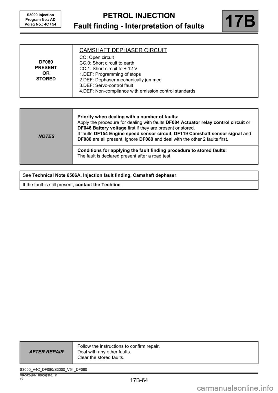
DF080
PRESENT
OR
STORED
CAMSHAFT DEPHASER CIRCUIT
CO: Open circuit
CC.0: Short circuit to earth
CC.1: Short circuit to + 12 V
1.DEF: Programming of stops
2.DEF: Dephaser mechanically jammed
3.DEF: Servo-control fault
4.DEF: Non-compliance with emission control standards
NOTESPriority when dealing with a number of faults:
Apply the procedure for dealing with faults DF084 Actuator relay control circuit or
DF046 Battery voltage first if they are present or stored.
If faults DF154 Engine speed sensor circuit, DF119 Camshaft sensor signal and
DF080 are all present, ignore DF080 and deal with the other 2 faults first.
Conditions for applying the fault finding procedure to stored faults:
The fault is declared present after a road test.
See Technical Note 6506A, Injection fault finding, Camshaft dephaser.
If the fault is still present, contact the Techline.
AFTER REPAIRFollow the instructions to confirm repair.
Deal with any other faults.
Clear the stored faults.
S3000_V4C_DF080/S3000_V54_DF080
MR-372-J84-17B050$376.mif
Page 65 of 230
PETROL INJECTION
Fault finding - Interpretation of faults
17B
17B-65
PETROL INJECTION
Fault finding - Interpretation of faults
17B
17B-65V9 MR-372-J84-17B050$376.mif
S3000 Injection
Program No.: AD
Vdiag No.: 4C / 54
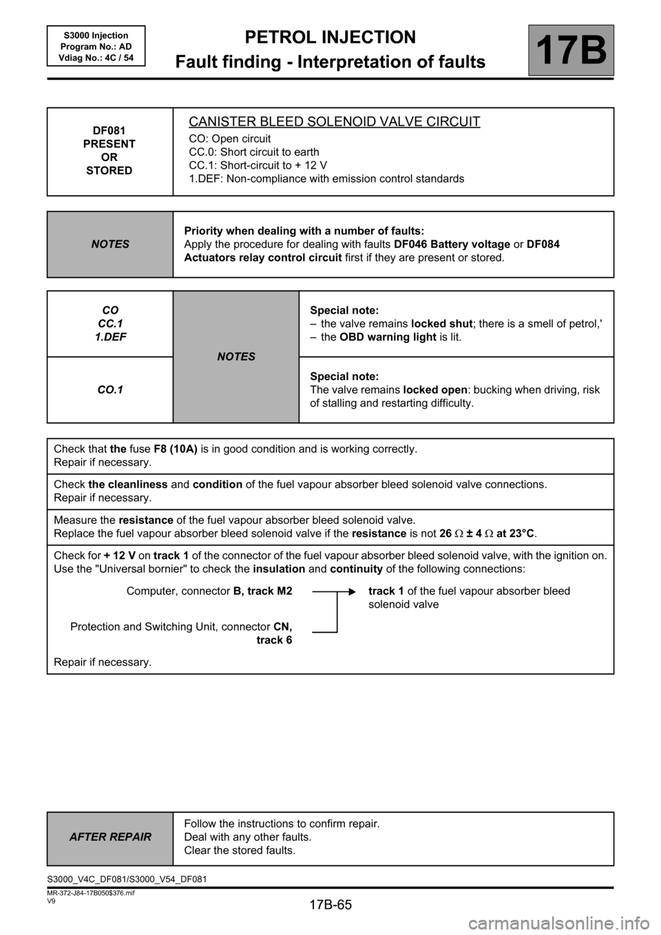
DF081
PRESENT
OR
STOREDCANISTER BLEED SOLENOID VALVE CIRCUIT
CO: Open circuit
CC.0: Short circuit to earth
CC.1: Short-circuit to + 12 V
1.DEF: Non-compliance with emission control standards
NOTESPriority when dealing with a number of faults:
Apply the procedure for dealing with faults DF046 Battery voltage or DF084
Actuators relay control circuit first if they are present or stored.
CO
CC.1
1.DEF
NOTESSpecial note:
– the valve remains locked shut; there is a smell of petrol,'
–the OBD warning light is lit.
CO.1Special note:
The valve remains locked open: bucking when driving, risk
of stalling and restarting difficulty.
Check that the fuseF8 (10A) is in good condition and is working correctly.
Repair if necessary.
Check the cleanliness and condition of the fuel vapour absorber bleed solenoid valve connections.
Repair if necessary.
Measure the resistance of the fuel vapour absorber bleed solenoid valve.
Replace the fuel vapour absorber bleed solenoid valve if the resistance is not 26Ω ±4Ω at 23°C.
Check for + 12 V on track 1 of the connector of the fuel vapour absorber bleed solenoid valve, with the ignition on.
Use the "Universal bornier" to check the insulation and continuity of the following connections:
Computer, connectorB, track M2 track 1 of the fuel vapour absorber bleed
solenoid valve
Protection and Switching Unit, connectorCN,
track 6
Repair if necessary.
AFTER REPAIRFollow the instructions to confirm repair.
Deal with any other faults.
Clear the stored faults.
S3000_V4C_DF081/S3000_V54_DF081
Page 71 of 230
PETROL INJECTION
Fault finding - Interpretation of faults
17B
17B-71
PETROL INJECTION
Fault finding - Interpretation of faults
17B
17B-71V9 MR-372-J84-17B050$376.mif
S3000 Injection
Program No.: AD
Vdiag No.: 4C / 54
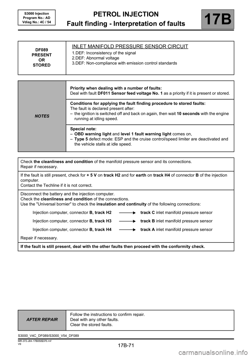
DF089
PRESENT
OR
STOREDINLET MANIFOLD PRESSURE SENSOR CIRCUIT
1.DEF: Inconsistency of the signal
2.DEF: Abnormal voltage
3.DEF: Non-compliance with emission control standards
NOTESPriority when dealing with a number of faults:
Deal with fault DF011 Sensor feed voltage No. 1 as a priority if it is present or stored.
Conditions for applying the fault finding procedure to stored faults:
The fault is declared present after:
– the ignition is switched off and back on again, then wait 10 seconds with the engine
running at idling speed.
Special note:
–OBD warning light and level 1 fault warning light comes on,
–Type 5 defect mode: ESP and the cruise control/speed limiter are deactivated and
the vehicle stalls at idle speed.
Check the cleanliness and condition of the manifold pressure sensor and its connections.
Repair if necessary.
If the fault is still present, check for + 5 V on track H2 and for earth on track H4 of connectorB of the injection
computer.
Contact the Techline if it is not correct.
Disconnect the battery and the injection computer.
Check the cleanliness and condition of the connections.
Use the "Universal bornier" to check the insulation and continuity of the following connections:
Injection computer, connectorB, track H2 track C inlet manifold pressure sensor
Injection computer, connectorB, track H3 track B inlet manifold pressure sensor
Injection computer, connectorB, track H4 track A inlet manifold pressure sensor
Repair if necessary.
If the fault is still present, deal with the other faults then proceed with the conformity check.
AFTER REPAIRFollow the instructions to confirm repair.
Deal with any other faults.
Clear the stored faults.
S3000_V4C_DF089/S3000_V54_DF089
Page 72 of 230

PETROL INJECTION
Fault finding - Interpretation of faults
17B
17B-72
PETROL INJECTION
Fault finding - Interpretation of faults
17B
17B-72V9 MR-372-J84-17B050$376.mif
S3000 Injection
Program No.: AD
Vdiag No.: 4C / 54
DF091
PRESENT
OR
STOREDVEHICLE SPEED SIGNAL
1.DEF: Multiplex network
2.DEF: Non-compliance with emission control standards
NOTESConditions for applying the fault finding procedure to stored faults:
The fault is declared present with the engine running.
Special note:
–OBD warning light illuminated.
Run a multiplex network test (see88B, Multiplexing).
Disconnect the battery and the injection computer.
Check the cleanliness and condition of the battery and the injection computer connections.
Repair if necessary.
If the fault is still present, carry out fault finding on the ABS - ESP system (see38C, Anti-lock braking system).
AFTER REPAIRFollow the instructions to confirm repair.
Deal with any other faults.
Clear the stored faults.
S3000_V4C_DF091/S3000_V54_DF091
Page 73 of 230
PETROL INJECTION
Fault finding - Interpretation of faults
17B
17B-73
PETROL INJECTION
Fault finding - Interpretation of faults
17B
17B-73V9 MR-372-J84-17B050$376.mif
S3000 Injection
Program No.: AD
Vdiag No.: 4C / 54
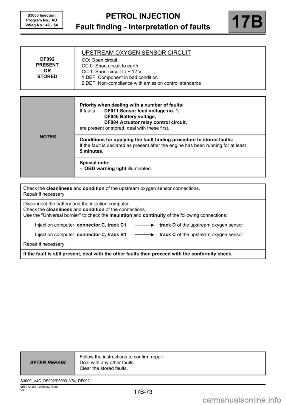
DF092
PRESENT
OR
STORED
UPSTREAM OXYGEN SENSOR CIRCUIT
CO: Open circuit
CC.0: Short circuit to earth
CC.1: Short-circuit to + 12 V
1.DEF: Component in bad condition
2.DEF: Non-compliance with emission control standards
NOTESPriority when dealing with a number of faults:
If faults DF011 Sensor feed voltage no. 1,
DF046 Battery voltage,
DF084 Actuator relay control circuit,
are present or stored, deal with these first.
Conditions for applying the fault finding procedure to stored faults:
If the fault is declared as present after the engine has been running for at least
5 minutes.
Special note:
–OBD warning light illuminated.
Check the cleanliness and condition of the upstream oxygen sensor connections.
Repair if necessary.
Disconnect the battery and the injection computer.
Check the cleanliness and condition of the connections.
Use the "Universal bornier" to check the insulation and continuity of the following connections:
Injection computer, connector C, track C1 track D of the upstream oxygen sensor
Injection computer, connector C, track B1 track C of the upstream oxygen sensor
Repair if necessary.
If the fault is still present, deal with the other faults then proceed with the conformity check.
AFTER REPAIRFollow the instructions to confirm repair.
Deal with any other faults.
Clear the stored faults.
S3000_V4C_DF092/S3000_V54_DF092
Page 74 of 230
PETROL INJECTION
Fault finding - Interpretation of faults
17B
17B-74
PETROL INJECTION
Fault finding - Interpretation of faults
17B
17B-74V9 MR-372-J84-17B050$376.mif
S3000 Injection
Program No.: AD
Vdiag No.: 4C / 54
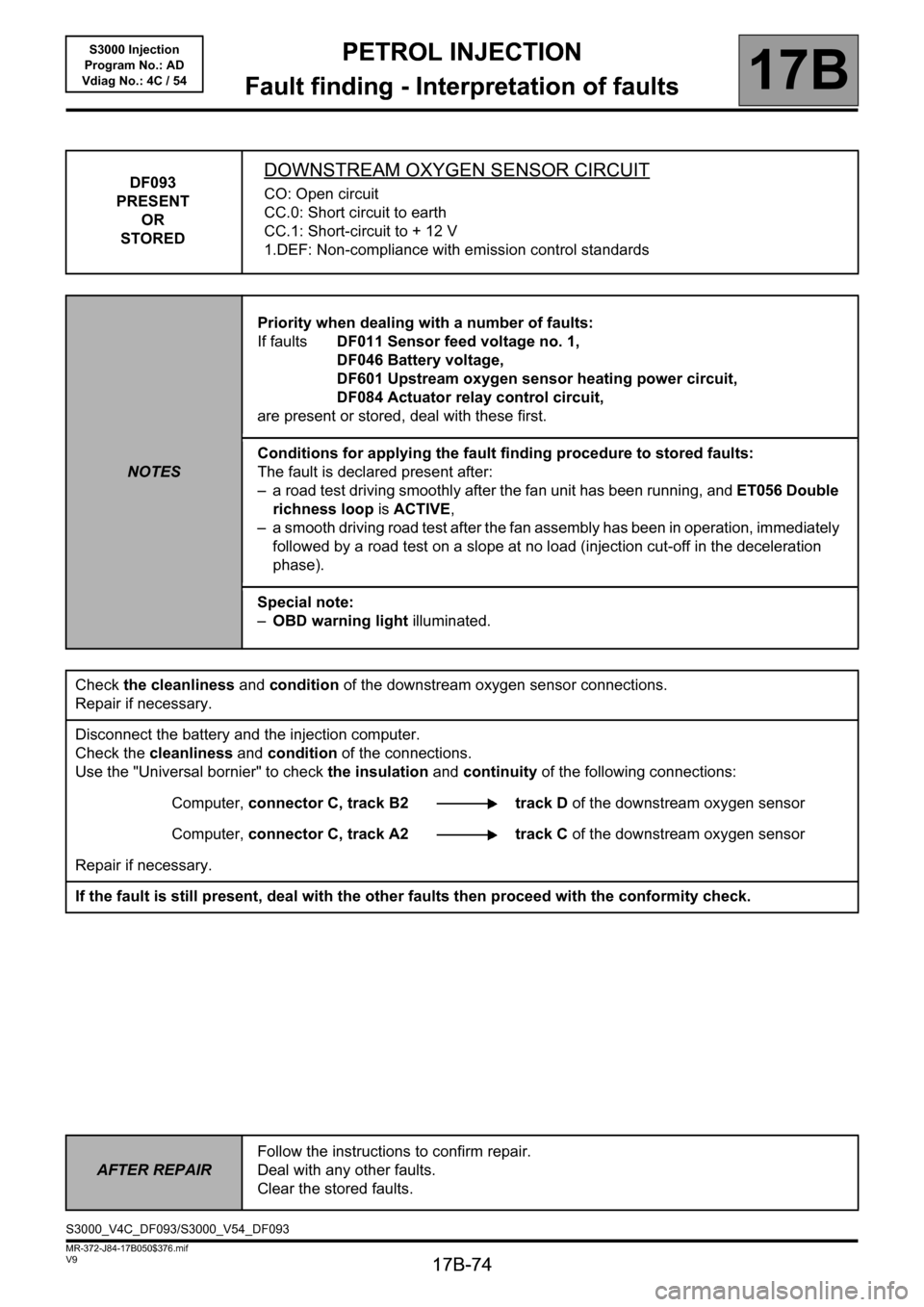
DF093
PRESENT
OR
STOREDDOWNSTREAM OXYGEN SENSOR CIRCUIT
CO: Open circuit
CC.0: Short circuit to earth
CC.1: Short-circuit to + 12 V
1.DEF: Non-compliance with emission control standards
NOTESPriority when dealing with a number of faults:
If faults DF011 Sensor feed voltage no. 1,
DF046 Battery voltage,
DF601 Upstream oxygen sensor heating power circuit,
DF084 Actuator relay control circuit,
are present or stored, deal with these first.
Conditions for applying the fault finding procedure to stored faults:
The fault is declared present after:
– a road test driving smoothly after the fan unit has been running, and ET056 Double
richness loop is ACTIVE,
– a smooth driving road test after the fan assembly has been in operation, immediately
followed by a road test on a slope at no load (injection cut-off in the deceleration
phase).
Special note:
–OBD warning light illuminated.
Check the cleanliness and condition of the downstream oxygen sensor connections.
Repair if necessary.
Disconnect the battery and the injection computer.
Check the cleanliness and condition of the connections.
Use the "Universal bornier" to check the insulation and continuity of the following connections:
Computer, connector C, track B2 track D of the downstream oxygen sensor
Computer, connector C, track A2 track C of the downstream oxygen sensor
Repair if necessary.
If the fault is still present, deal with the other faults then proceed with the conformity check.
AFTER REPAIRFollow the instructions to confirm repair.
Deal with any other faults.
Clear the stored faults.
S3000_V4C_DF093/S3000_V54_DF093