battery RENAULT SCENIC 2010 J95 / 3.G Petrol Injection S3000 Injection Repair Manual
[x] Cancel search | Manufacturer: RENAULT, Model Year: 2010, Model line: SCENIC, Model: RENAULT SCENIC 2010 J95 / 3.GPages: 230, PDF Size: 0.92 MB
Page 101 of 230
PETROL INJECTION
Fault finding - Interpretation of faults
17B
17B-101
PETROL INJECTION
Fault finding - Interpretation of faults
17B
17B-101V9 MR-372-J84-17B050$423.mif
S3000 Injection
Program No.: AD
Vdiag No.: 4C / 54
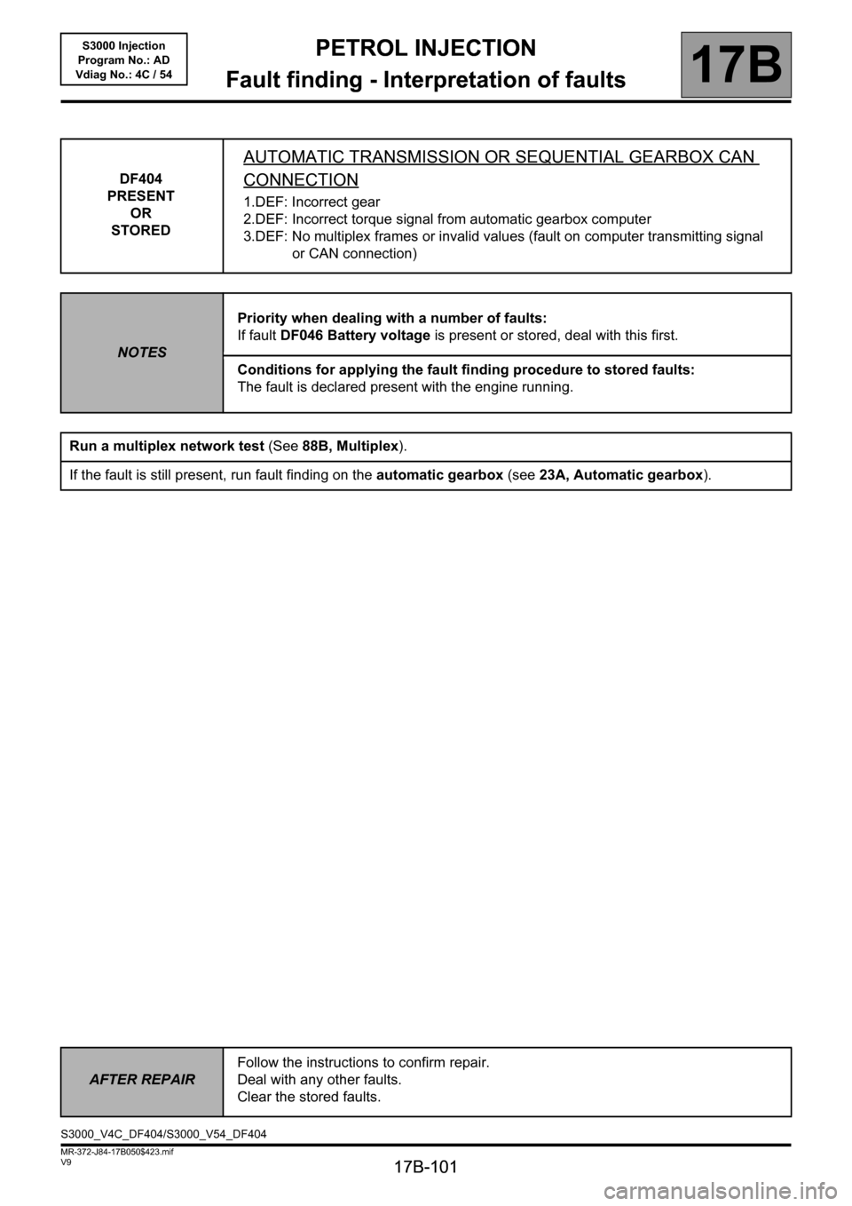
DF404
PRESENT
OR
STORED
AUTOMATIC TRANSMISSION OR SEQUENTIAL GEARBOX CAN
CONNECTION
1.DEF: Incorrect gear
2.DEF: Incorrect torque signal from automatic gearbox computer
3.DEF: No multiplex frames or invalid values (fault on computer transmitting signal
or CAN connection)
NOTESPriority when dealing with a number of faults:
If fault DF046 Battery voltage is present or stored, deal with this first.
Conditions for applying the fault finding procedure to stored faults:
The fault is declared present with the engine running.
Run a multiplex network test (See88B, Multiplex).
If the fault is still present, run fault finding on the automatic gearbox (see 23A, Automatic gearbox).
AFTER REPAIRFollow the instructions to confirm repair.
Deal with any other faults.
Clear the stored faults.
S3000_V4C_DF404/S3000_V54_DF404
Page 108 of 230
PETROL INJECTION
Fault finding - Interpretation of faults
17B
17B-108
PETROL INJECTION
Fault finding - Interpretation of faults
17B
17B-108V9 MR-372-J84-17B050$423.mif
S3000 Injection
Program No.: AD
Vdiag No.: 4C / 54
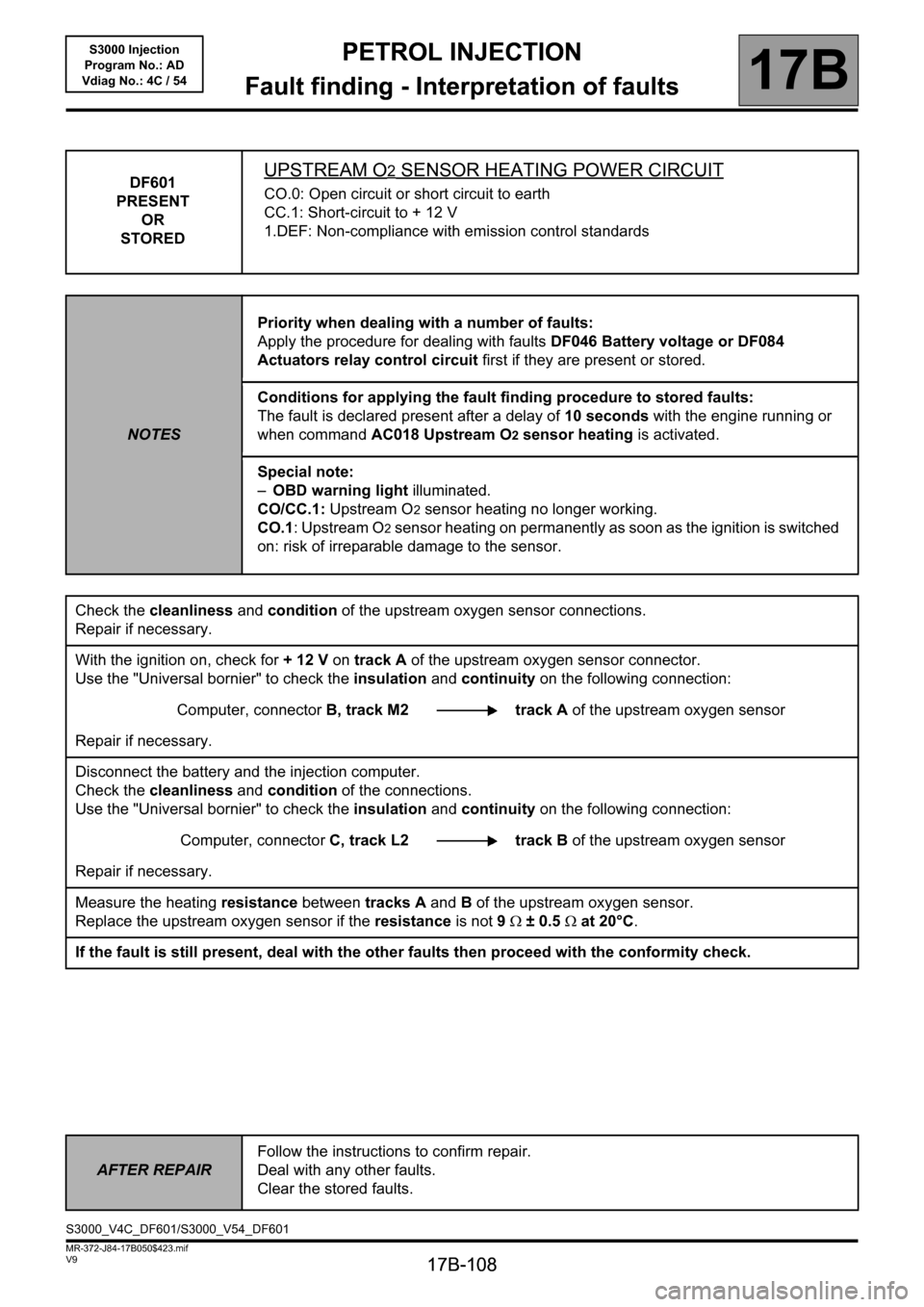
DF601
PRESENT
OR
STOREDUPSTREAM O2 SENSOR HEATING POWER CIRCUIT
CO.0: Open circuit or short circuit to earth
CC.1: Short-circuit to + 12 V
1.DEF: Non-compliance with emission control standards
NOTESPriority when dealing with a number of faults:
Apply the procedure for dealing with faults DF046 Battery voltage or DF084
Actuators relay control circuit first if they are present or stored.
Conditions for applying the fault finding procedure to stored faults:
The fault is declared present after a delay of 10 seconds with the engine running or
when command AC018 Upstream O2 sensor heating is activated.
Special note:
–OBD warning light illuminated.
CO/CC.1: Upstream O
2 sensor heating no longer working.
CO.1: Upstream O
2 sensor heating on permanently as soon as the ignition is switched
on: risk of irreparable damage to the sensor.
Check the cleanliness and condition of the upstream oxygen sensor connections.
Repair if necessary.
With the ignition on, check for + 12 V on track A of the upstream oxygen sensor connector.
Use the "Universal bornier" to check the insulation and continuity on the following connection:
Computer, connectorB, track M2 track A of the upstream oxygen sensor
Repair if necessary.
Disconnect the battery and the injection computer.
Check the cleanliness and condition of the connections.
Use the "Universal bornier" to check the insulation and continuity on the following connection:
Computer, connectorC, track L2 track B of the upstream oxygen sensor
Repair if necessary.
Measure the heating resistance between tracks A and B of the upstream oxygen sensor.
Replace the upstream oxygen sensor if the resistance is not 9Ω ± 0.5Ω at 20°C.
If the fault is still present, deal with the other faults then proceed with the conformity check.
AFTER REPAIRFollow the instructions to confirm repair.
Deal with any other faults.
Clear the stored faults.
S3000_V4C_DF601/S3000_V54_DF601
Page 109 of 230
PETROL INJECTION
Fault finding - Interpretation of faults
17B
17B-109
PETROL INJECTION
Fault finding - Interpretation of faults
17B
17B-109V9 MR-372-J84-17B050$423.mif
S3000 Injection
Program No.: AD
Vdiag No.: 4C / 54
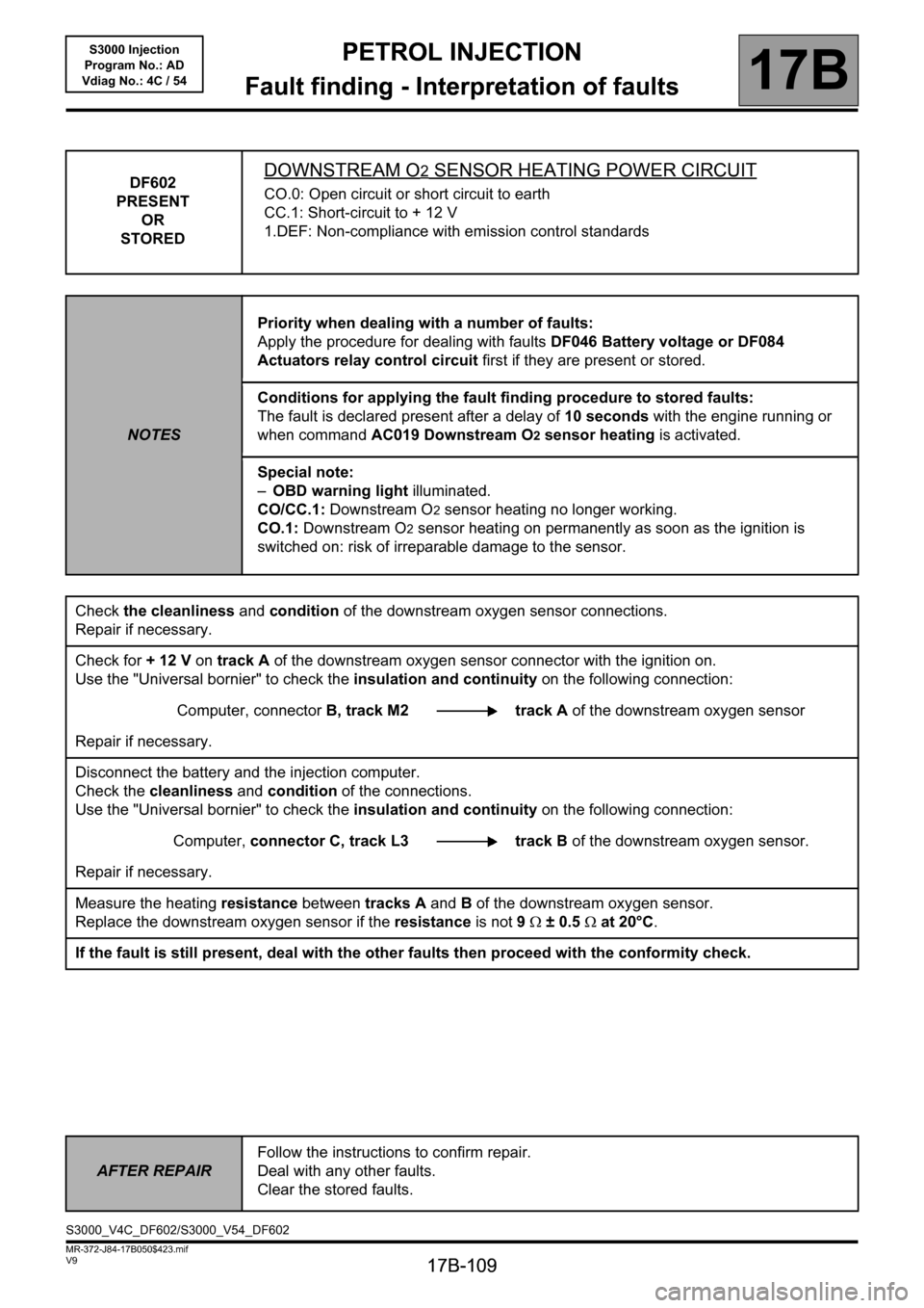
DF602
PRESENT
OR
STOREDDOWNSTREAM O2 SENSOR HEATING POWER CIRCUIT
CO.0: Open circuit or short circuit to earth
CC.1: Short-circuit to + 12 V
1.DEF: Non-compliance with emission control standards
NOTESPriority when dealing with a number of faults:
Apply the procedure for dealing with faults DF046 Battery voltage or DF084
Actuators relay control circuit first if they are present or stored.
Conditions for applying the fault finding procedure to stored faults:
The fault is declared present after a delay of 10 seconds with the engine running or
when command AC019 Downstream O2 sensor heating is activated.
Special note:
–OBD warning light illuminated.
CO/CC.1: Downstream O
2 sensor heating no longer working.
CO.1: Downstream O
2 sensor heating on permanently as soon as the ignition is
switched on: risk of irreparable damage to the sensor.
Check the cleanliness and condition of the downstream oxygen sensor connections.
Repair if necessary.
Check for + 12 V on track A of the downstream oxygen sensor connector with the ignition on.
Use the "Universal bornier" to check the insulation and continuity on the following connection:
Computer, connectorB, track M2 track A of the downstream oxygen sensor
Repair if necessary.
Disconnect the battery and the injection computer.
Check the cleanliness and condition of the connections.
Use the "Universal bornier" to check the insulation and continuity on the following connection:
Computer, connector C, track L3 track Bof the downstream oxygen sensor.
Repair if necessary.
Measure the heating resistance between tracks A and B of the downstream oxygen sensor.
Replace the downstream oxygen sensor if the resistance is not 9Ω ± 0.5Ω at 20°C.
If the fault is still present, deal with the other faults then proceed with the conformity check.
AFTER REPAIRFollow the instructions to confirm repair.
Deal with any other faults.
Clear the stored faults.
S3000_V4C_DF602/S3000_V54_DF602
Page 110 of 230
PETROL INJECTION
Fault finding - Interpretation of faults
17B
17B-110
PETROL INJECTION
Fault finding - Interpretation of faults
17B
17B-110V9 MR-372-J84-17B050$423.mif
S3000 Injection
Program No.: AD
Vdiag No.: 4C / 54
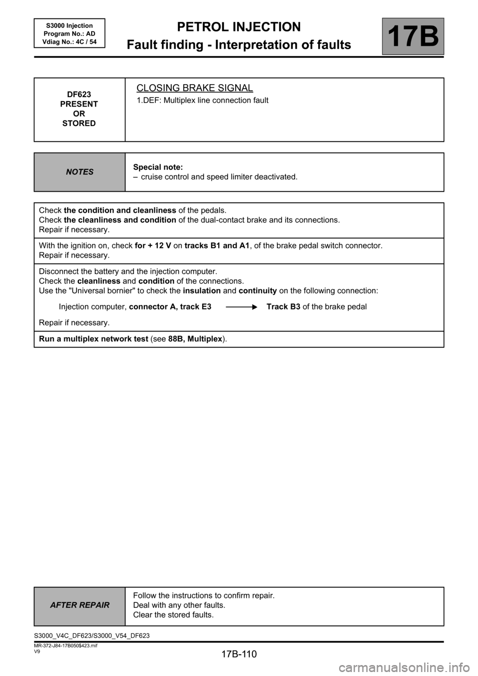
DF623
PRESENT
OR
STOREDCLOSING BRAKE SIGNAL
1.DEF: Multiplex line connection fault
NOTESSpecial note:
– cruise control and speed limiter deactivated.
Check the condition and cleanliness of the pedals.
Check the cleanliness and condition of the dual-contact brake and its connections.
Repair if necessary.
With the ignition on, check for + 12 V on tracks B1 and A1, of the brake pedal switch connector.
Repair if necessary.
Disconnect the battery and the injection computer.
Check the cleanliness and condition of the connections.
Use the "Universal bornier" to check the insulation and continuity on the following connection:
Injection computer, connector A, track E3 Track B3 of the brake pedal
Repair if necessary.
Run a multiplex network test (see88B, Multiplex).
AFTER REPAIRFollow the instructions to confirm repair.
Deal with any other faults.
Clear the stored faults.
S3000_V4C_DF623/S3000_V54_DF623
Page 111 of 230
PETROL INJECTION
Fault finding - Interpretation of faults
17B
17B-111
PETROL INJECTION
Fault finding - Interpretation of faults
17B
17B-111V9 MR-372-J84-17B050$423.mif
S3000 Injection
Program No.: AD
Vdiag No.: 4C / 54
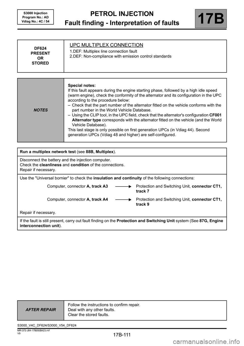
DF624
PRESENT
OR
STOREDUPC MULTIPLEX CONNECTION
1.DEF: Multiplex line connection fault
2.DEF: Non-compliance with emission control standards
NOTESSpecial notes:
If this fault appears during the engine starting phase, followed by a high idle speed
(warm engine), check the conformity of the alternator and its configuration in the UPC
according to the procedure below:
– Check that the part number of the alternator fitted on the vehicle conforms with the
part number in the World Vehicle Database.
– Using the CLIP tool, in the UPC field, check that the alternator's configuration CF001
Alternator type corresponds with the alternator fitted on the vehicle (and the World
Vehicle Database).
This last stage is only possible on first generation UPCs (in Vdiag 44). Second
generation UPCs (Vdiag 48 and higher) are self-configured.
Run a multiplex network test (see88B, Multiplex).
Disconnect the battery and the injection computer.
Check the cleanliness and condition of the connections.
Repair if necessary.
Use the "Universal bornier" to check the insulation and continuity of the following connections:
Computer, connectorA, track A3Protection and Switching Unit, connector CT1,
track 7
Computer, connectorA, track A4Protection and Switching Unit, connector CT1,
track 9
Repair if necessary.
If the fault is still present, carry out fault finding on the Protection and Switching Unit system (See87G, Engine
interconnection unit).
AFTER REPAIRFollow the instructions to confirm repair.
Deal with any other faults.
Clear the stored faults.
S3000_V4C_DF624/S3000_V54_DF624
Page 118 of 230
PETROL INJECTION
Fault finding - Interpretation of faults
17B
17B-118
PETROL INJECTION
Fault finding - Interpretation of faults
17B
17B-118V9 MR-372-J84-17B050$423.mif
S3000 Injection
Program No.: AD
Vdiag No.: 4C / 54
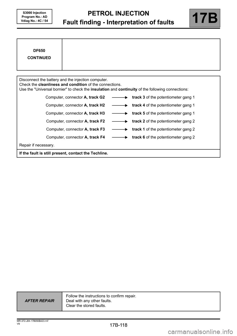
DF650
CONTINUED
Disconnect the battery and the injection computer.
Check the cleanliness and condition of the connections.
Use the "Universal bornier" to check the insulation and continuity of the following connections:
Computer, connectorA, track G2 track 3 of the potentiometer gang 1
Computer, connectorA, track H2 track 4 of the potentiometer gang 1
Computer, connectorA, track H3 track 5 of the potentiometer gang 1
Computer, connectorA, track F2 track 2 of the potentiometer gang 2
Computer, connectorA, track F3 track 1 of the potentiometer gang 2
Computer, connectorA, track F4 track 6 of the potentiometer gang 2
Repair if necessary.
If the fault is still present, contact the Techline.
AFTER REPAIRFollow the instructions to confirm repair.
Deal with any other faults.
Clear the stored faults.
Page 120 of 230

PETROL INJECTION
Fault finding - Conformity check
17B
17B-120
PETROL INJECTION
Fault finding - Conformity check
17B
17B-120V9 MR-372-J84-17B050$470.mif
S3000 Injection
Program No.: AD
Vdiag No.: 4C / 54PETROL INJECTION
Fault finding - Conformity check
MAIN COMPUTER STATUSES AND PARAMETERS
NOTESOnly check the conformity after a complete check with the diagnostic tool. The values
shown in this conformity check are given as a guide.
Application conditions: engine stopped, ignition on.
Order FunctionParameter or Status Checked
or ActionDisplay and notes Fault finding
1
Battery voltageET001:Computer + after
ignition feedPresentIn the event of a fault,
apply the
interpretation of
DF046 Battery
voltage. 2 PR074:Battery voltage11 V < PR074 < 15 V
3 Vehicle speed PR089:Vehicle speedGives the vehicle
speed in mph (km/h).
This parameter is
sent to the injection
by the ABS computer
via the multiplex
network.
PR089= 0mphIn the event of a fault
apply the
interpretation for
DF091 Vehicle speed
signal.
4
FaultsET064:Level 1 injection faultYES
NO
WITHOUT 5ET065:Level 2 Injection faultYES
NO
6 PR105:OBD fault warning
light lit mileage
counterIndicates the mileage
covered with the
OBD warning light lit.
7 PR106:Mileage counter fault
warning light litShows the distance
covered with the
warning light lit.
S3000_V4C_CCONF/S3000_V54_CCONF
MR-372-J84-17B050$470.mif
Page 142 of 230

PETROL INJECTION
Fault finding - Conformity check
17B
17B-142
PETROL INJECTION
Fault finding - Conformity check
17B
17B-142V9 MR-372-J84-17B050$470.mif
S3000 Injection
Program No.: AD
Vdiag No.: 4C / 54
STARTING SUB-FUNCTION:
NOTESOnly check the conformity after a complete check with the diagnostic tool. The values
shown in this conformity check are given as a guide.
Application conditions: Engine off, ignition on.
Order FunctionParameter or Status
Checked or ActionDisplay and notes Fault finding
1StartingET076:StartingAUTHORISEDAuthorisation to start is
given once the petrol
pump is pressurised
and if the motorised
throttle has emerged
from the stop and limp-
home position
programming phase.
2Actuator relay
controlET048:Actuator relay
controlACTIVEIf INACTIVE, apply the
interpretation of DF084
Actuator relay control
circuit.
3 Battery voltage PR074:Battery voltage11 V < PR074 < 15 VIn the event of a fault,
apply the interpretation of
DF046 Battery voltage.
4 Impact signal ET077:Impact
detectedNOIn the event of a fault,
run a multiplex network
test using the
diagnostic tool; then, if
the test is OK, carry out
fault finding on the
airbag computer.
Page 144 of 230

PETROL INJECTION
Fault finding - Conformity check
17B
17B-144
PETROL INJECTION
Fault finding - Conformity check
17B
17B-144V9 MR-372-J84-17B050$470.mif
S3000 Injection
Program No.: AD
Vdiag No.: 4C / 54
MAIN COMPUTER STATUSES AND PARAMETERS
NOTESOnly perform this conformity check after a complete check with the diagnostic tool.
The values shown in this conformity check are given as a guide.
Application conditions: Engine warm, idling.
Order FunctionParameter or Status Checked
or ActionDisplay and notes Fault finding
1
Battery voltageET001:Computer + after
ignition feedPresentIn the event of a fault,
apply the
interpretation of
DF046 Battery
voltage. 2 PR074:Battery voltage11 V < PR074 < 15 V
3 Vehicle speed PR089:Vehicle speedGives the vehicle
speed in mph (km/h).
This parameter is
sent to the injection
by the ABS computer
via the multiplex
network.If there is a fault use
the interpretation for
DF091 Vehicle speed
signal.
4
FaultsET064:Level 1 injection faultYES
NO
WITHOUT 5ET065:Level 2 Injection faultYES
NO
6 PR105:OBD fault warning
light lit mileage
counterIndicates the mileage
covered with the
OBD warning light lit.
7 PR106:Mileage counter fault
warning light litShows the distance
covered with the
warning light lit.
Page 166 of 230

PETROL INJECTION
Fault finding - Conformity check
17B
17B-166
PETROL INJECTION
Fault finding - Conformity check
17B
17B-166V9 MR-372-J84-17B050$517.mif
S3000 Injection
Program No.: AD
Vdiag No.: 4C / 54
STARTING SUB-FUNCTION:
NOTESOnly perform this conformity check after a complete check with the diagnostic tool.
The values shown in this conformity check are given as a guide.
Application conditions: Engine warm, idling.
Order FunctionParameter or Status
Checked or ActionDisplay and notes Fault finding
1StartingET076:StartingAUTHORISEDAuthorisation to start is
given once the petrol
pump is pressurised
and if the motorised
throttle has emerged
from the stop and limp-
home position
programming phase.
2Actuator relay
controlET048:Actuator relay
controlACTIVEIf INACTIVE, apply the
interpretation of DF084
Actuator relay control
circuit.
3 Battery voltage PR074:Battery voltage11 V < PR074 < 15 VIn the event of a fault,
apply the interpretation of
DF046 Battery voltage.
4 Impact signal ET077:Impact
detectedNOIn the event of a fault,
run a multiplex network
test using the
diagnostic tool; then, if
the test is OK, carry out
fault finding on the
airbag computer.