RENAULT SCENIC 2011 J95 / 3.G Engine And Peripherals EDC16 Injection Workshop Manual
Manufacturer: RENAULT, Model Year: 2011, Model line: SCENIC, Model: RENAULT SCENIC 2011 J95 / 3.GPages: 236, PDF Size: 1.32 MB
Page 111 of 236
13B-111
DIESEL INJECTION
Fault finding - Conformity check13B
V10 MR-372-J84-13B150$423.mif
EDC16 INJECTION
Program No.: C1
Vdiag No: 44, 48 and 4C
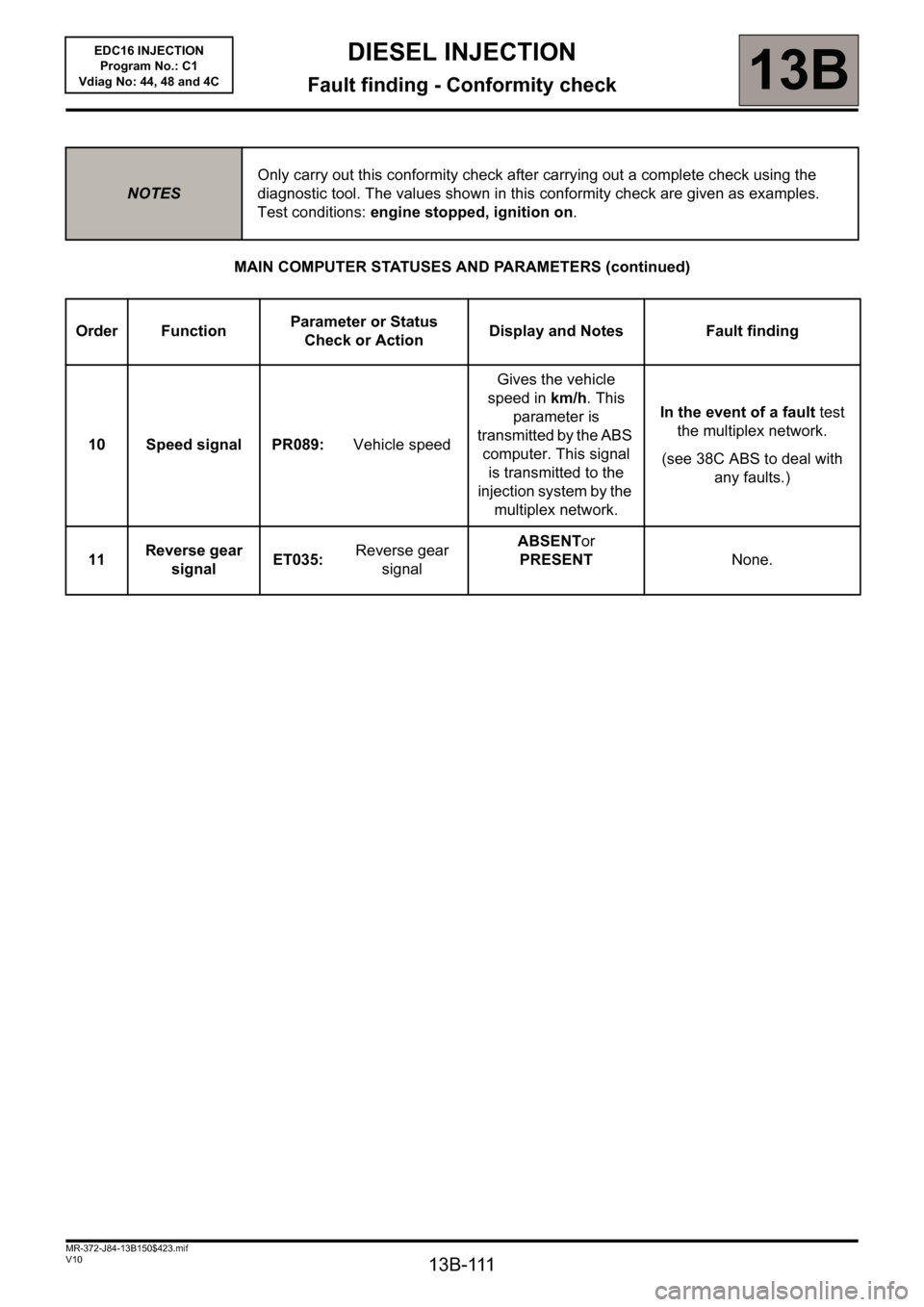
MAIN COMPUTER STATUSES AND PARAMETERS (continued)
NOTESOnly carry out this conformity check after carrying out a complete check using the
diagnostic tool. The values shown in this conformity check are given as examples.
Test conditions: engine stopped, ignition on.
Order FunctionParameter or Status
Check or ActionDisplay and Notes Fault finding
10 Speed signal PR089: Vehicle speed Gives the vehicle
speed in km/h. This
parameter is
transmitted by the ABS
computer. This signal
is transmitted to the
injection system by the
multiplex network.In the event of a fault test
the multiplex network.
(see 38C ABS to deal with
any faults.)
11Reverse gear
signalET035: Reverse gear
signalABSENTor
PRESENTNone.
Page 112 of 236
13B-112
DIESEL INJECTION
Fault finding - Conformity check13B
V10 MR-372-J84-13B150$423.mif
EDC16 INJECTION
Program No.: C1
Vdiag No: 44, 48 and 4C
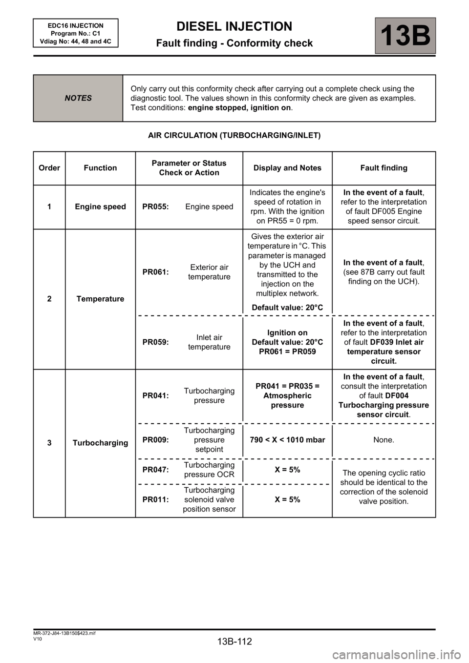
AIR CIRCULATION (TURBOCHARGING/INLET)
NOTESOnly carry out this conformity check after carrying out a complete check using the
diagnostic tool. The values shown in this conformity check are given as examples.
Test conditions: engine stopped, ignition on.
Order FunctionParameter or Status
Check or ActionDisplay and Notes Fault finding
1 Engine speed PR055:Engine speedIndicates the engine's
speed of rotation in
rpm. With the ignition
on PR55 = 0 rpm.In the event of a fault,
refer to the interpretation
of fault DF005 Engine
speed sensor circuit.
2 TemperaturePR061:Exterior air
temperatureGives the exterior air
temperature in °C. This
parameter is managed
by the UCH and
transmitted to the
injection on the
multiplex network.
Default value: 20°CIn the event of a fault,
(see 87B carry out fault
finding on the UCH).
PR059:Inlet air
temperatureIgnition on
Default value: 20°C
PR061 = PR059In the event of a fault,
refer to the interpretation
of fault DF039 Inlet air
temperature sensor
circuit.
3 TurbochargingPR041:Turbocharging
pressurePR041 = PR035 =
Atmospheric
pressureIn the event of a fault,
consult the interpretation
of fault DF004
Turbocharging pressure
sensor circuit.
PR009:Turbocharging
pressure
setpoint790 < X < 1010 mbarNone.
PR047:Turbocharging
pressure OCRX= 5%
The opening cyclic ratio
should be identical to the
correction of the solenoid
valve position. PR011:Turbocharging
solenoid valve
position sensorX= 5%
Page 113 of 236
13B-113
DIESEL INJECTION
Fault finding - Conformity check13B
V10 MR-372-J84-13B150$423.mif
EDC16 INJECTION
Program No.: C1
Vdiag No: 44, 48 and 4C
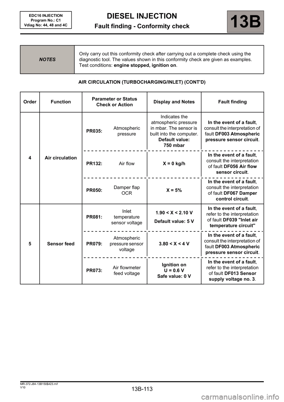
AIR CIRCULATION (TURBOCHARGING/INLET) (CONT'D)
NOTESOnly carry out this conformity check after carrying out a complete check using the
diagnostic tool. The values shown in this conformity check are given as examples.
Test conditions: engine stopped, ignition on.
Order FunctionParameter or Status
Check or ActionDisplay and Notes Fault finding
4 Air circulationPR035:Atmospheric
pressureIndicates the
atmospheric pressure
in mbar. The sensor is
built into the computer.
Default value:
750 mbarIn the event of a fault,
consult the interpretation of
fault DF003 Atmospheric
pressure sensor circuit.
PR132:Air flowX = 0 kg/hIn the event of a fault,
consult the interpretation
of fault DF056 Air flow
sensor circuit.
PR050:Damper flap
OCRX= 5%In the event of a fault,
consult the interpretation
of fault DF067 Damper
control circuit.
5 Sensor feedPR081:Inlet
temperature
sensor voltage1.90 < X < 2.10 V
Default value: 5 VIn the event of a fault,
refer to the interpretation
of fault DF039 "Inlet air
temperature circuit"
PR079:Atmospheric
pressure sensor
voltage3.80 < X < 4 VIn the event of a fault,
consult the interpretation of
fault DF003 Atmospheric
pressure sensor circuit.
PR073:Air flowmeter
feed voltageIgnition on
U= 0.6V
Safe value: 0 VIn the event of a fault,
refer to the interpretation
of fault DF013 Sensor
supply voltage no. 3.
Page 114 of 236
13B-114
DIESEL INJECTION
Fault finding - Conformity check13B
V10 MR-372-J84-13B150$423.mif
EDC16 INJECTION
Program No.: C1
Vdiag No: 44, 48 and 4C
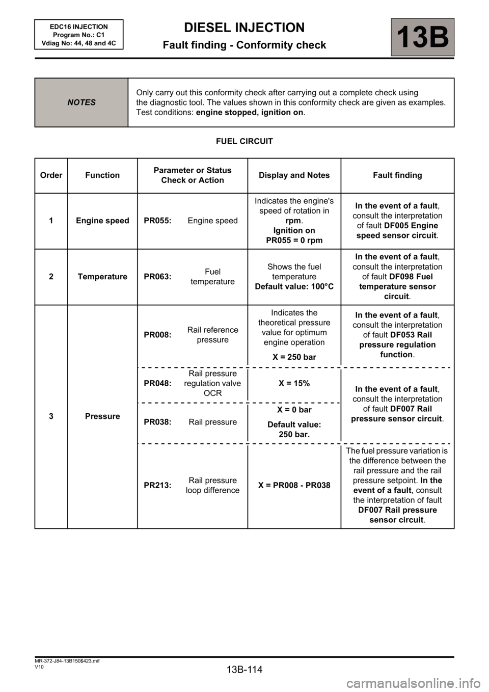
FUEL CIRCUIT
NOTESOnly carry out this conformity check after carrying out a complete check using
the diagnostic tool. The values shown in this conformity check are given as examples.
Test conditions: engine stopped, ignition on.
Order FunctionParameter or Status
Check or ActionDisplay and Notes Fault finding
1 Engine speed PR055: Engine speedIndicates the engine's
speed of rotation in
rpm.
Ignition on
PR055= 0rpmIn the event of a fault,
consult the interpretation
of fault DF005 Engine
speed sensor circuit.
2 Temperature PR063: Fuel
temperatureShows the fuel
temperature
Default value: 100°CIn the event of a fault,
consult the interpretation
of fault DF098 Fuel
temperature sensor
circuit.
3 PressurePR008: Rail reference
pressureIndicates the
theoretical pressure
value for optimum
engine operation
X = 250 barIn the event of a fault,
consult the interpretation
of fault DF053 Rail
pressure regulation
function.
PR048: Rail pressure
regulation valve
OCRX= 15%
In the event of a fault,
consult the interpretation
of fault DF007 Rail
pressure sensor circuit.
PR038: Rail pressureX = 0 bar
Default value:
250 bar.
PR213: Rail pressure
loop differenceX = PR008 - PR038The fuel pressure variation is
the difference between the
rail pressure and the rail
pressure setpoint. In the
event of a fault, consult
the interpretation of fault
DF007 Rail pressure
sensor circuit.
Page 115 of 236
13B-115
DIESEL INJECTION
Fault finding - Conformity check13B
V10 MR-372-J84-13B150$423.mif
EDC16 INJECTION
Program No.: C1
Vdiag No: 44, 48 and 4C
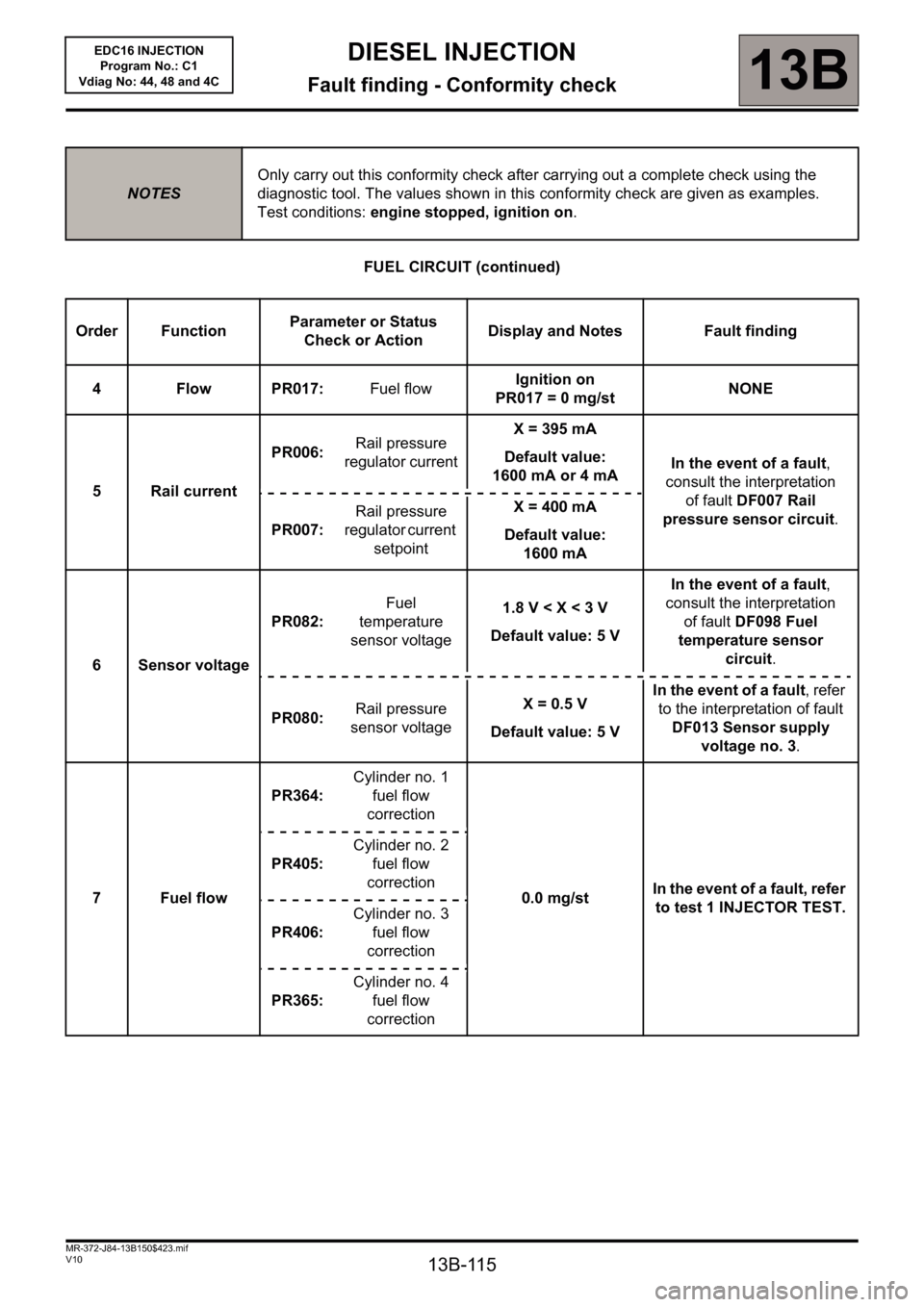
FUEL CIRCUIT (continued)
NOTESOnly carry out this conformity check after carrying out a complete check using the
diagnostic tool. The values shown in this conformity check are given as examples.
Test conditions: engine stopped, ignition on.
Order FunctionParameter or Status
Check or ActionDisplay and Notes Fault finding
4 Flow PR017: Fuel flowIgnition on
PR017= 0mg/stNONE
5 Rail currentPR006: Rail pressure
regulator currentX = 395 mA
Default value:
1600 mA or 4 mAIn the event of a fault,
consult the interpretation
of fault DF007 Rail
pressure sensor circuit.
PR007: Rail pressure
regulator current
setpointX = 400 mA
Default value:
1600 mA
6 Sensor voltagePR082: Fuel
temperature
sensor voltage1.8 V < X < 3 V
Default value: 5 VIn the event of a fault,
consult the interpretation
of fault DF098 Fuel
temperature sensor
circuit.
PR080: Rail pressure
sensor voltageX= 0.5V
Default value: 5 VIn the event of a fault, refer
to the interpretation of fault
DF013 Sensor supply
voltage no. 3.
7 Fuel flowPR364:Cylinder no. 1
fuel flow
correction
0.0 mg/stIn the event of a fault, refer
to test 1 INJECTOR TEST. PR405:Cylinder no. 2
fuel flow
correction
PR406:Cylinder no. 3
fuel flow
correction
PR365:Cylinder no. 4
fuel flow
correction
Page 116 of 236
13B-116
DIESEL INJECTION
Fault finding - Conformity check13B
V10 MR-372-J84-13B150$423.mif
EDC16 INJECTION
Program No.: C1
Vdiag No: 44, 48 and 4C
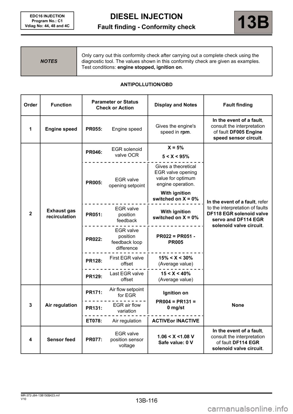
ANTIPOLLUTION/OBD
NOTESOnly carry out this conformity check after carrying out a complete check using the
diagnostic tool. The values shown in this conformity check are given as examples.
Test conditions: engine stopped, ignition on.
Order FunctionParameter or Status
Check or ActionDisplay and Notes Fault finding
1 Engine speed PR055: Engine speedGives the engine's
speed in rpm.In the event of a fault,
consult the interpretation
of fault DF005 Engine
speed sensor circuit.
2Exhaust gas
recirculationPR046: EGR solenoid
valve OCRX= 5%
5< X <95%
In the event of a fault, refer
to the interpretation of faults
DF118 EGR solenoid valve
servo and DF114 EGR
solenoid valve circuit. PR005: EGR valve
opening setpointGives a theoretical
EGR valve opening
value for optimum
engine operation.
With ignition
switched on X = 0%
PR051: EGR valve
position
feedbackWith ignition
switched on X = 0%
PR022: EGR valve
position
feedback loop
differencePR022 = PR051 -
PR005
PR128: First EGR valve
offset15% < X < 30%
(Average value)
PR129: Last EGR valve
offset15
3 Air regulationPR171: Air flow setpoint
for EGRIgnition on
PR004 = PR131 =
0mg/stNone
PR131: EGR air flow
variation
ET078: Air regulationACTIVEor INACTIVE
4 Sensor feed PR077: EGR valve
position sensor
voltage1.06 < X <1.08 V
Safe value: 0 VIn the event of a fault,
consult the interpretation
of fault DF114 EGR
solenoid valve circuit.
Page 117 of 236
13B-117
DIESEL INJECTION
Fault finding - Conformity check13B
V10 MR-372-J84-13B150$423.mif
EDC16 INJECTION
Program No.: C1
Vdiag No: 44, 48 and 4C
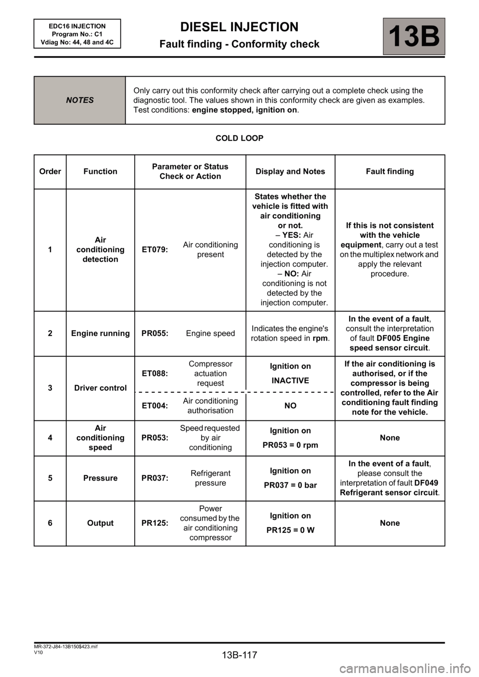
COLD LOOP
NOTESOnly carry out this conformity check after carrying out a complete check using the
diagnostic tool. The values shown in this conformity check are given as examples.
Test conditions: engine stopped, ignition on.
Order FunctionParameter or Status
Check or ActionDisplay and Notes Fault finding
1Air
conditioning
detectionET079: Air conditioning
presentStates whether the
vehicle is fitted with
air conditioning
or not.
–YES: Air
conditioning is
detected by the
injection computer.
–NO: Air
conditioning is not
detected by the
injection computer.If this is not consistent
with the vehicle
equipment, carry out a test
on the multiplex network and
apply the relevant
procedure.
2 Engine running PR055: Engine speedIndicates the engine's
rotation speed in rpm.In the event of a fault,
consult the interpretation
of fault DF005 Engine
speed sensor circuit.
3 Driver controlET088: Compressor
actuation
requestIgnition on
INACTIVEIf the air conditioning is
authorised, or if the
compressor is being
controlled, refer to the Air
conditioning fault finding
note for the vehicle. ET004: Air conditioning
authorisationNO
4Air
conditioning
speedPR053: Speed requested
by air
conditioningIgnition on
PR053= 0rpmNone
5 Pressure PR037: Refrigerant
pressureIgnition on
PR037 = 0 barIn the event of a fault,
please consult the
interpretation of fault DF049
Refrigerant sensor circuit.
6OutputPR125: Power
consumed by the
air conditioning
compressor
Ignition on
PR125 = 0 WNone
Page 118 of 236
13B-118
DIESEL INJECTION
Fault finding - Conformity check13B
V10 MR-372-J84-13B150$423.mif
EDC16 INJECTION
Program No.: C1
Vdiag No: 44, 48 and 4C
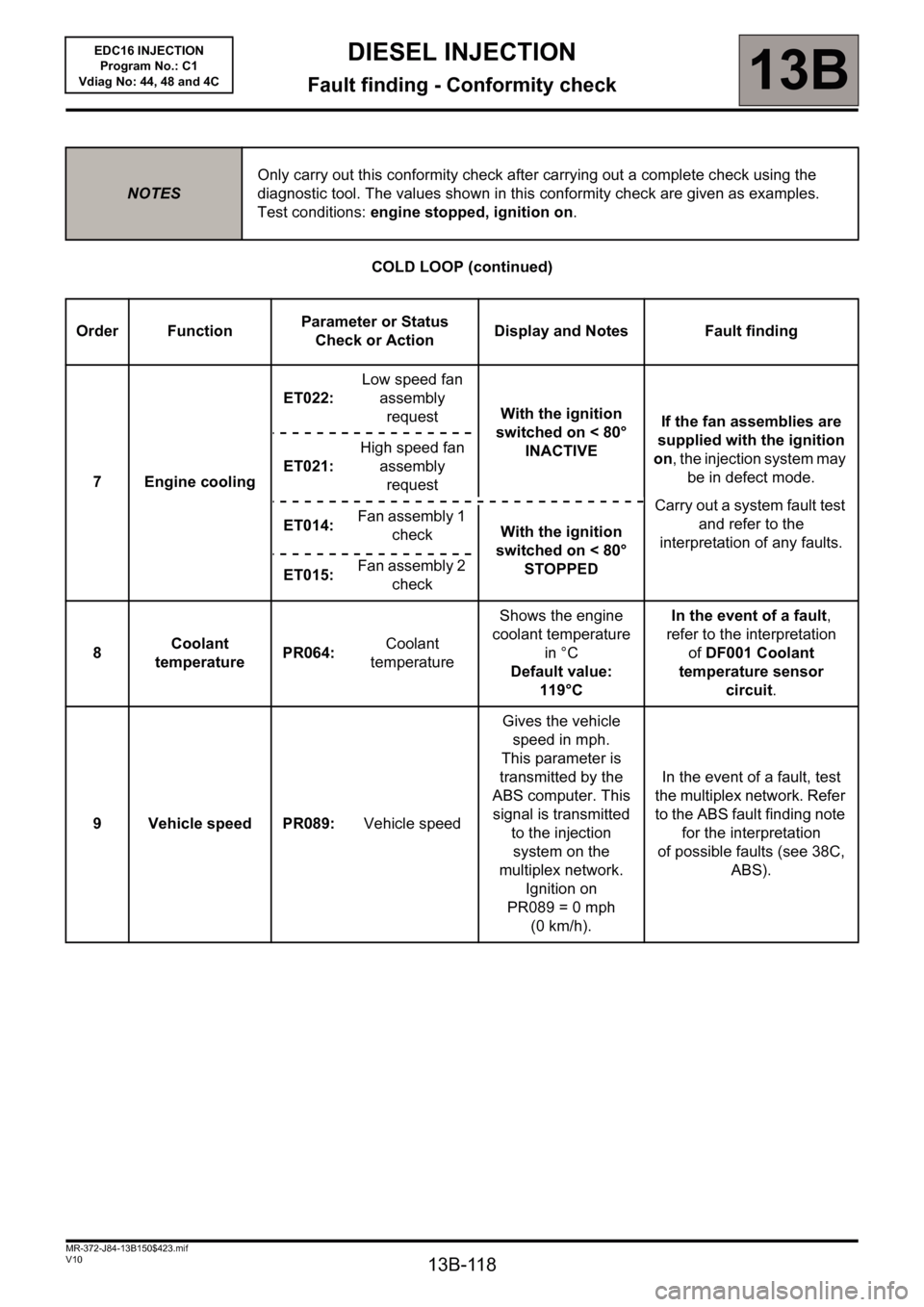
COLD LOOP (continued)
NOTESOnly carry out this conformity check after carrying out a complete check using the
diagnostic tool. The values shown in this conformity check are given as examples.
Test conditions: engine stopped, ignition on.
Order FunctionParameter or Status
Check or ActionDisplay and Notes Fault finding
7 Engine coolingET022: Low speed fan
assembly
requestWith the ignition
switched on < 80°
INACTIVEIf the fan assemblies are
supplied with the ignition
on, the injection system may
be in defect mode.
Carry out a system fault test
and refer to the
interpretation of any faults. ET021: High speed fan
assembly
request
ET014: Fan assembly 1
checkWith the ignition
switched on < 80°
STOPPED
ET015: Fan assembly 2
check
8Coolant
temperaturePR064: Coolant
temperatureShows the engine
coolant temperature
in °C
Default value:
119°CIn the event of a fault,
refer to the interpretation
ofDF001 Coolant
temperature sensor
circuit.
9 Vehicle speed PR089: Vehicle speedGives the vehicle
speed in mph.
This parameter is
transmitted by the
ABS computer. This
signal is transmitted
to the injection
system on the
multiplex network.
Ignition on
PR089 = 0 mph
(0 km/h).In the event of a fault, test
the multiplex network. Refer
to the ABS fault finding note
for the interpretation
of possible faults (see 38C,
ABS).
Page 119 of 236
13B-119
DIESEL INJECTION
Fault finding - Conformity check13B
V10 MR-372-J84-13B150$423.mif
EDC16 INJECTION
Program No.: C1
Vdiag No: 44, 48 and 4C
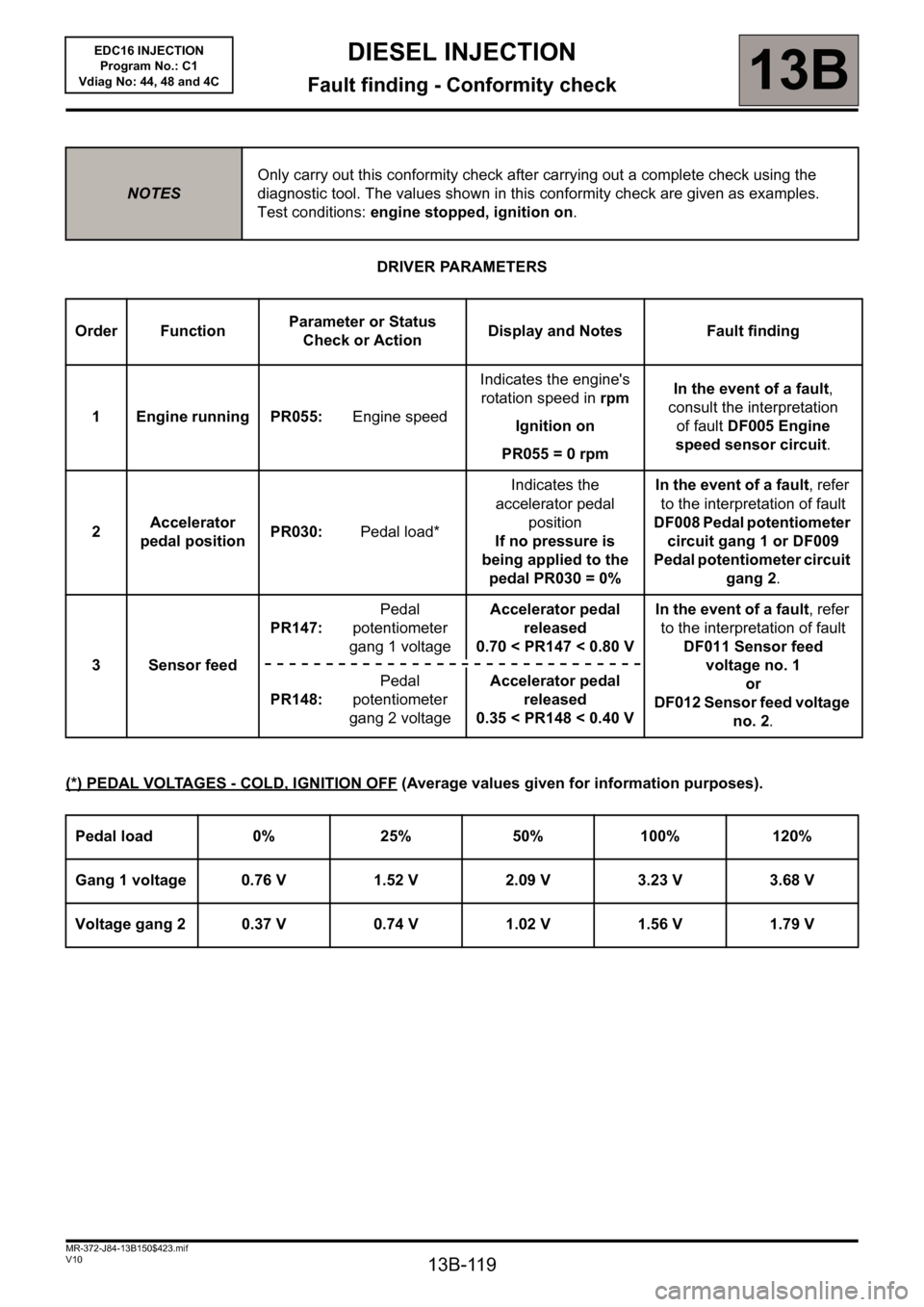
DRIVER PARAMETERS
(*) PEDAL VOLTAGES - COLD, IGNITION OFF
(Average values given for information purposes).
NOTESOnly carry out this conformity check after carrying out a complete check using the
diagnostic tool. The values shown in this conformity check are given as examples.
Test conditions: engine stopped, ignition on.
Order FunctionParameter or Status
Check or ActionDisplay and Notes Fault finding
1 Engine running PR055: Engine speedIndicates the engine's
rotation speed in rpm
Ignition on
PR055 = 0 rpmIn the event of a fault,
consult the interpretation
of fault DF005 Engine
speed sensor circuit.
2Accelerator
pedal positionPR030: Pedal load*Indicates the
accelerator pedal
position
If no pressure is
being applied to the
pedal PR030 = 0%In the event of a fault, refer
to the interpretation of fault
DF008 Pedal potentiometer
circuit gang 1 or DF009
Pedal potentiometer circuit
gang 2.
3 Sensor feedPR147: Pedal
potentiometer
gang 1 voltageAccelerator pedal
released
0.70 < PR147 < 0.80 VIn the event of a fault, refer
to the interpretation of fault
DF011 Sensor feed
voltage no. 1
or
DF012 Sensor feed voltage
no. 2. PR148: Pedal
potentiometer
gang 2 voltageAccelerator pedal
released
0.35 < PR148 < 0.40 V
Pedal load 0% 25% 50% 100% 120%
Gang 1 voltage 0.76 V 1.52 V 2.09 V 3.23 V 3.68 V
Voltage gang 2 0.37 V 0.74 V 1.02 V 1.56 V 1.79 V
Page 120 of 236
13B-120
DIESEL INJECTION
Fault finding - Conformity check13B
V10 MR-372-J84-13B150$423.mif
EDC16 INJECTION
Program No.: C1
Vdiag No: 44, 48 and 4C
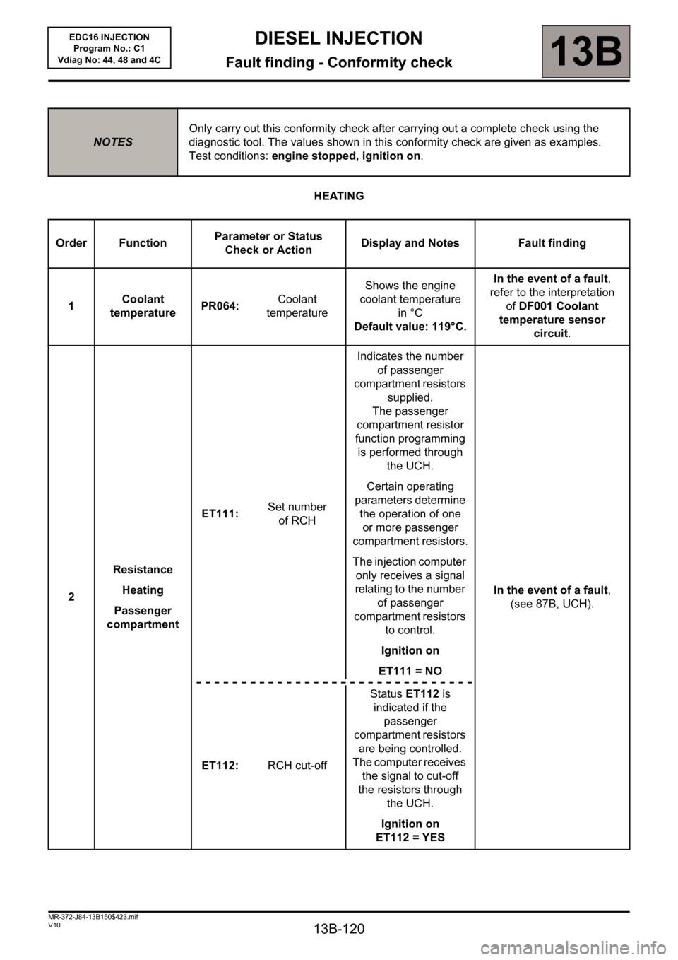
HEATING
NOTESOnly carry out this conformity check after carrying out a complete check using the
diagnostic tool. The values shown in this conformity check are given as examples.
Test conditions: engine stopped, ignition on.
Order FunctionParameter or Status
Check or ActionDisplay and Notes Fault finding
1Coolant
temperaturePR064: Coolant
temperatureShows the engine
coolant temperature
in °C
Default value: 119°C.In the event of a fault,
refer to the interpretation
ofDF001 Coolant
temperature sensor
circuit.
2Resistance
Heating
Passenger
compartmentET111: Set number
of RCHIndicates the number
of passenger
compartment resistors
supplied.
The passenger
compartment resistor
function programming
is performed through
the UCH.
Certain operating
parameters determine
the operation of one
or more passenger
compartment resistors.
The injection computer
only receives a signal
relating to the number
of passenger
compartment resistors
to control.
Ignition on
ET111 = NOIn the event of a fault,
(see 87B, UCH).
ET112: RCH cut-offStatus ET112 is
indicated if the
passenger
compartment resistors
are being controlled.
The computer receives
the signal to cut-off
the resistors through
the UCH.
Ignition on
ET112 = YES