ECU RENAULT SCENIC 2011 J95 / 3.G Engine And Peripherals EDC16 Injection User Guide
[x] Cancel search | Manufacturer: RENAULT, Model Year: 2011, Model line: SCENIC, Model: RENAULT SCENIC 2011 J95 / 3.GPages: 236, PDF Size: 1.32 MB
Page 78 of 236
13B-78
DIESEL INJECTION
Fault finding - Interpretation of faults13B
V10 MR-372-J84-13B150$329.mif
EDC16 INJECTION
Program No.: C1
Vdiag No.: 44, 48 and 4C
DF057
PRESENT
OR
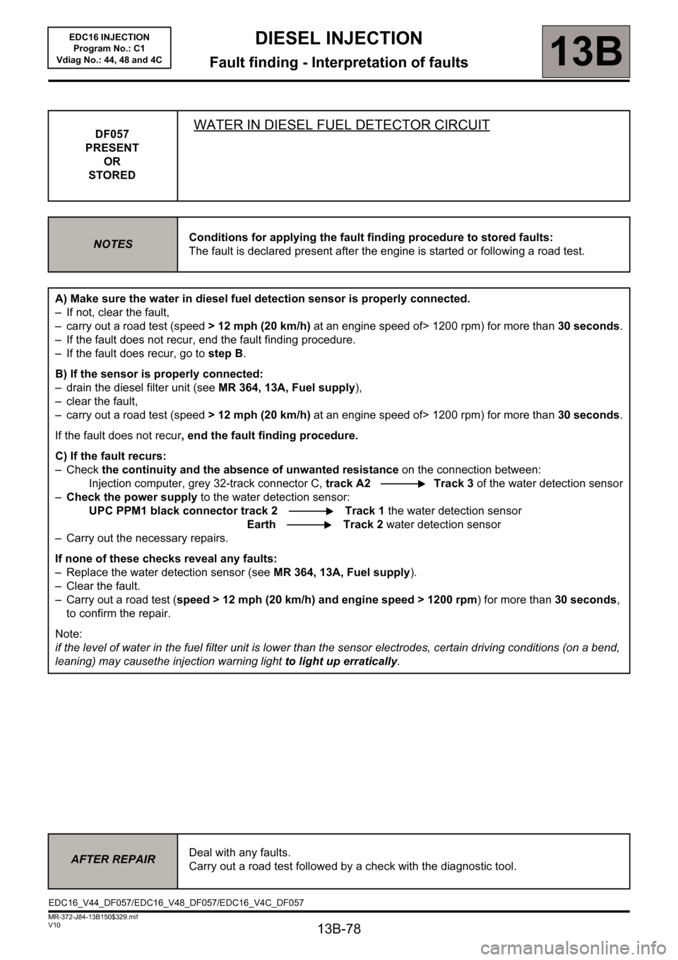
STOREDWATER IN DIESEL FUEL DETECTOR CIRCUIT
NOTESConditions for applying the fault finding procedure to stored faults:
The fault is declared present after the engine is started or following a road test.
A) Make sure the water in diesel fuel detection sensor is properly connected.
– If not, clear the fault,
– carry out a road test (speed > 12 mph (20 km/h) at an engine speed of> 1200 rpm) for more than 30 seconds.
– If the fault does not recur, end the fault finding procedure.
– If the fault does recur, go to step B.
B) If the sensor is properly connected:
– drain the diesel filter unit (seeMR 364, 13A, Fuel supply),
– clear the fault,
– carry out a road test (speed > 12 mph (20 km/h) at an engine speed of> 1200 rpm) for more than 30 seconds.
If the fault does not recur, end the fault finding procedure.
C) If the fault recurs:
–Check the continuity and the absence of unwanted resistance on the connection between:
Injection computer, grey 32-track connector C, track A2 Track 3 of the water detection sensor
–Check the power supply to the water detection sensor:
UPC PPM1 black connector track 2 Track 1 the water detection sensor
Earth Track 2 water detection sensor
– Carry out the necessary repairs.
If none of these checks reveal any faults:
– Replace the water detection sensor (see MR 364, 13A, Fuel supply).
– Clear the fault.
– Carry out a road test (speed > 12 mph (20 km/h) and engine speed > 1200 rpm) for more than 30 seconds,
to confirm the repair.
Note:
if the level of water in the fuel filter unit is lower than the sensor electrodes, certain driving conditions (on a bend,
leaning) may causethe injection warning light to light up erratically.
AFTER REPAIRDeal with any faults.
Carry out a road test followed by a check with the diagnostic tool.
EDC16_V44_DF057/EDC16_V48_DF057/EDC16_V4C_DF057
Page 82 of 236
13B-82
DIESEL INJECTION
Fault finding - Interpretation of faults
13B
V10 MR-372-J84-13B150$376.mif
EDC16 INJECTION
Program No.: C1
Vdiag No.: 44, 48 and 4C
DF069
PRESENT
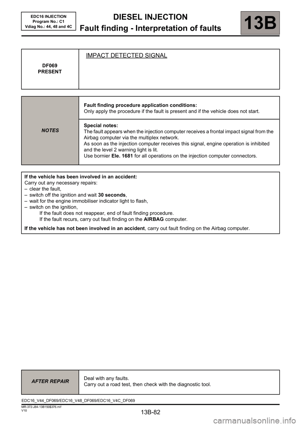
IMPACT DETECTED SIGNAL
NOTESFault finding procedure application conditions:
Only apply the procedure if the fault is present and if the vehicle does not start.
Special notes:
The fault appears when the injection computer receives a frontal impact signal from the
Airbag computer via the multiplex network.
As soon as the injection computer receives this signal, engine operation is inhibited
and the level 2 warning light is lit.
Use bornier Ele. 1681 for all operations on the injection computer connectors.
If the vehicle has been involved in an accident:
Carry out any necessary repairs:
– clear the fault,
– switch off the ignition and wait 30 seconds,
– wait for the engine immobiliser indicator light to flash,
– switch on the ignition,
If the fault does not reappear, end of fault finding procedure.
If the fault recurs, carry out fault finding on the AIRBAG computer.
If the vehicle has not been involved in an accident, carry out fault finding on the Airbag computer.
AFTER REPAIRDeal with any faults.
Carry out a road test, then check with the diagnostic tool.
EDC16_V44_DF069/EDC16_V48_DF069/EDC16_V4C_DF069
Page 95 of 236
13B-95
DIESEL INJECTION
Fault finding - Interpretation of faults
13B
V10 MR-372-J84-13B150$376.mif
EDC16 INJECTION
Program No.: C1
Vdiag No.: 44, 48 and 4C
DF209
PRESENT
OR
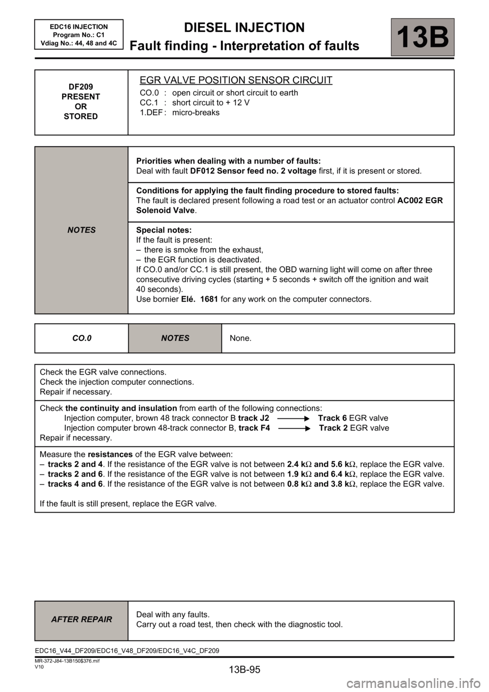
STOREDEGR VALVE POSITION SENSOR CIRCUIT
CO.0 : open circuit or short circuit to earth
CC.1 : short circuit to + 12 V
1.DEF : micro-breaks
NOTESPriorities when dealing with a number of faults:
Deal with fault DF012 Sensor feed no. 2 voltage first, if it is present or stored.
Conditions for applying the fault finding procedure to stored faults:
The fault is declared present following a road test or an actuator control AC002 EGR
Solenoid Valve.
Special notes:
If the fault is present:
– there is smoke from the exhaust,
– the EGR function is deactivated.
If CO.0 and/or CC.1 is still present, the OBD warning light will come on after three
consecutive driving cycles (starting + 5 seconds + switch off the ignition and wait
40 seconds).
Use bornier Elé. 1681 for any work on the computer connectors.
CO.0
NOTESNone.
Check the EGR valve connections.
Check the injection computer connections.
Repair if necessary.
Check the continuity and insulation from earth of the following connections:
Injection computer, brown 48 track connector B track J2 Track 6 EGR valve
Injection computer brown 48-track connector B, track F4 Track 2 EGR valve
Repair if necessary.
Measure the resistances of the EGR valve between:
–tracks 2 and 4. If the resistance of the EGR valve is not between 2.4 kΩ and 5.6 kΩ, replace the EGR valve.
–tracks 2 and 6. If the resistance of the EGR valve is not between 1.9 kΩ and 6.4 kΩ, replace the EGR valve.
–tracks 4 and 6. If the resistance of the EGR valve is not between 0.8 kΩ and 3.8 kΩ, replace the EGR valve.
If the fault is still present, replace the EGR valve.
AFTER REPAIRDeal with any faults.
Carry out a road test, then check with the diagnostic tool.
EDC16_V44_DF209/EDC16_V48_DF209/EDC16_V4C_DF209
Page 99 of 236
13B-99
DIESEL INJECTION
Fault finding - Interpretation of faults
13B
V10 MR-372-J84-13B150$376.mif
EDC16 INJECTION
Program No.: C1
Vdiag No.: 44, 48 and 4C
DF272
PRESENT
OR
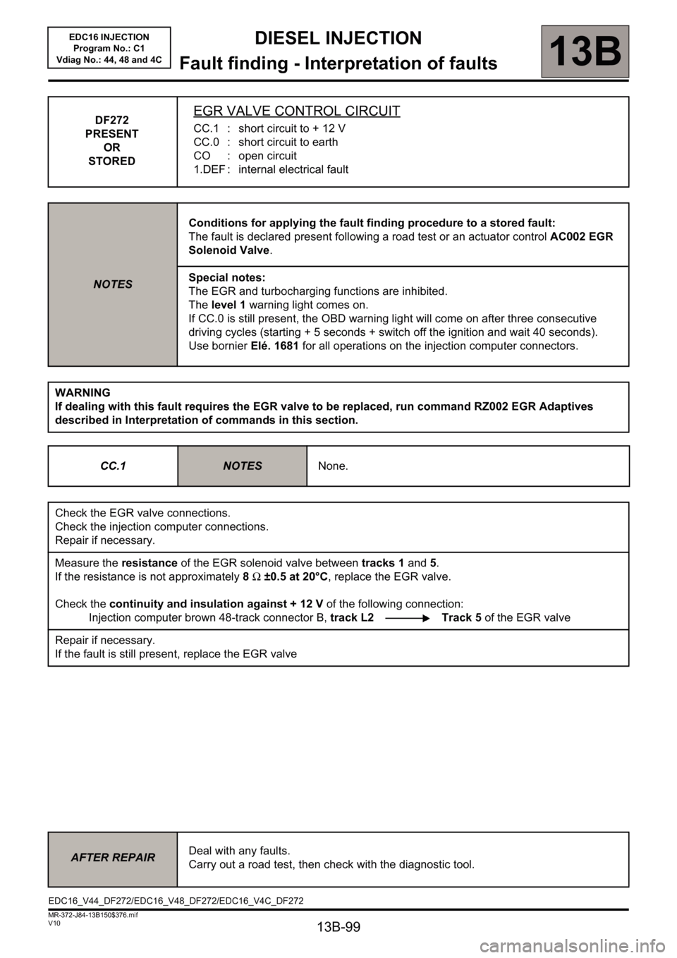
STOREDEGR VALVE CONTROL CIRCUIT
CC.1 : short circuit to + 12 V
CC.0 : short circuit to earth
CO : open circuit
1.DEF : internal electrical fault
NOTESConditions for applying the fault finding procedure to a stored fault:
The fault is declared present following a road test or an actuator control AC002 EGR
Solenoid Valve.
Special notes:
The EGR and turbocharging functions are inhibited.
The level 1 warning light comes on.
If CC.0 is still present, the OBD warning light will come on after three consecutive
driving cycles (starting + 5 seconds + switch off the ignition and wait 40 seconds).
Use bornier Elé. 1681 for all operations on the injection computer connectors.
WARNING
If dealing with this fault requires the EGR valve to be replaced, run command RZ002 EGR Adaptives
described in Interpretation of commands in this section.
CC.1
NOTESNone.
Check the EGR valve connections.
Check the injection computer connections.
Repair if necessary.
Measure the resistance of the EGR solenoid valve between tracks 1 and 5.
If the resistance is not approximately 8 Ω ±0.5 at 20°C, replace the EGR valve.
Check the continuity and insulation against + 12 V of the following connection:
Injection computer brown 48-track connector B, track L2 Track 5 of the EGR valve
Repair if necessary.
If the fault is still present, replace the EGR valve
AFTER REPAIRDeal with any faults.
Carry out a road test, then check with the diagnostic tool.
EDC16_V44_DF272/EDC16_V48_DF272/EDC16_V4C_DF272
Page 106 of 236
13B-106
DIESEL INJECTION
Fault finding - Interpretation of faults
13B
V10 MR-372-J84-13B150$376.mif
EDC16 INJECTION
Program No.: C1
Vdiag No.: 48 and 4C
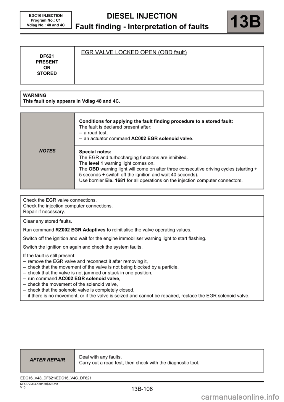
DF621
PRESENT
OR
STOREDEGR VALVE LOCKED OPEN (OBD fault)
WARNING
This fault only appears in Vdiag 48 and 4C.
NOTESConditions for applying the fault finding procedure to a stored fault:
The fault is declared present after:
– a road test,
– an actuator command AC002 EGR solenoid valve.
Special notes:
The EGR and turbocharging functions are inhibited.
The level 1 warning light comes on.
The OBD warning light will come on after three consecutive driving cycles (starting +
5 seconds + switch off the ignition and wait 40 seconds).
Use bornier Ele. 1681 for all operations on the injection computer connectors.
Check the EGR valve connections.
Check the injection computer connections.
Repair if necessary.
Clear any stored faults.
Run command RZ002 EGR Adaptives to reinitialise the valve operating values.
Switch off the ignition and wait for the engine immobiliser warning light to start flashing.
Switch the ignition on again and check the system faults.
If the fault is still present:
– remove the EGR valve and reconnect it after removing it,
– check that the movement of the valve is not being blocked by a particle,
– check that the valve is not jammed or stuck in one position,
– run command AC002 EGR solenoid valve,
– check the movement of the solenoid valve,
– check that the solenoid valve is completely closed,
– if there is no movement, or if the valve is seized and cannot be repaired, replace the EGR solenoid valve.
AFTER REPAIRDeal with any faults.
Carry out a road test, then check with the diagnostic tool.
EDC16_V48_DF621/EDC16_V4C_DF621
Page 192 of 236
13B - 192
DIESEL INJECTION
Fault finding - Interpretation of commands13B
V10 MR-372-J84-13B150$752.mif
EDC16 INJECTION
Program No.: C1
Vdiag No: 44, 48 and 4C
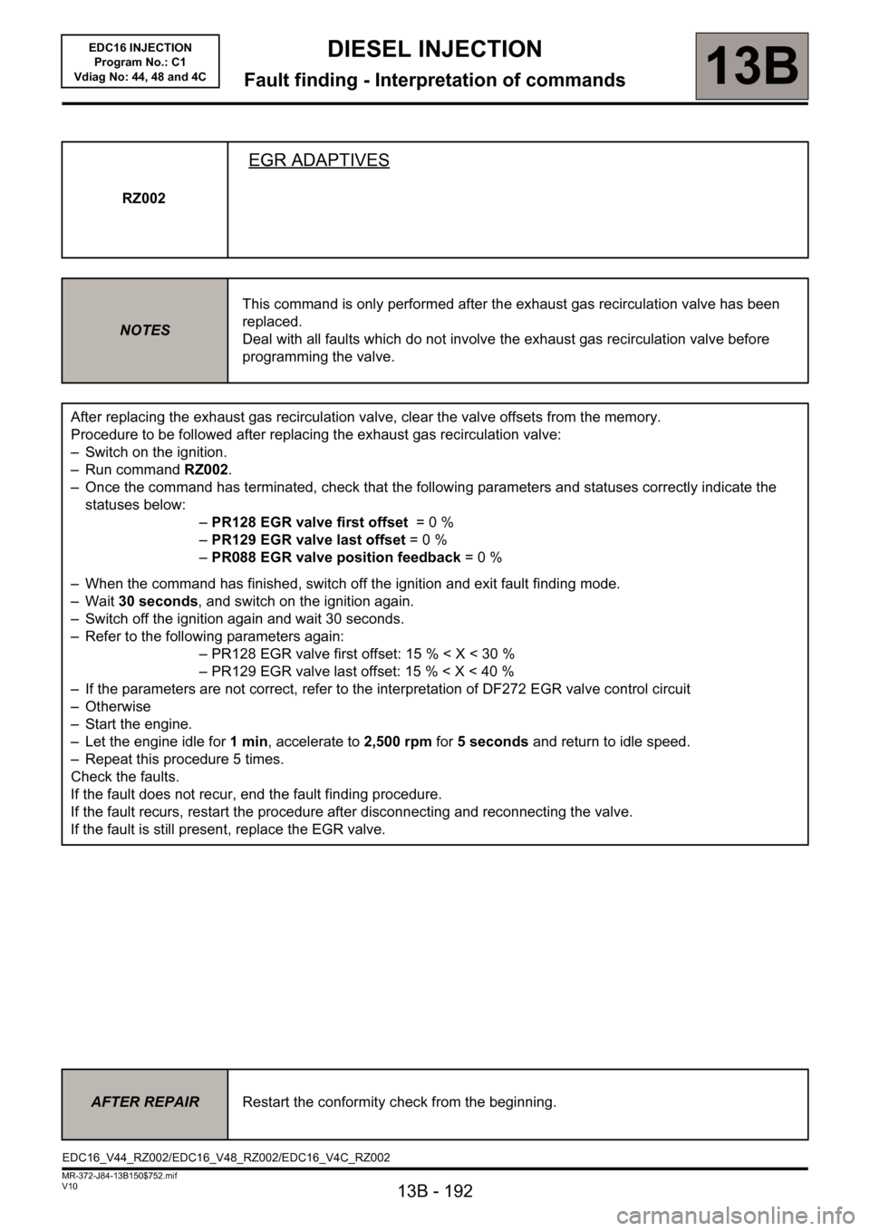
RZ002
EGR ADAPTIVES
NOTESThis command is only performed after the exhaust gas recirculation valve has been
replaced.
Deal with all faults which do not involve the exhaust gas recirculation valve before
programming the valve.
After replacing the exhaust gas recirculation valve, clear the valve offsets from the memory.
Procedure to be followed after replacing the exhaust gas recirculation valve:
– Switch on the ignition.
– Run command RZ002.
– Once the command has terminated, check that the following parameters and statuses correctly indicate the
statuses below:
–PR128 EGR valve first offset = 0 %
–PR129 EGR valve last offset= 0 %
–PR088 EGR valve position feedback= 0 %
– When the command has finished, switch off the ignition and exit fault finding mode.
–Wait 30 seconds, and switch on the ignition again.
– Switch off the ignition again and wait 30 seconds.
– Refer to the following parameters again:
– PR128 EGR valve first offset: 15 % < X < 30 %
– PR129 EGR valve last offset: 15 % < X < 40 %
– If the parameters are not correct, refer to the interpretation of DF272 EGR valve control circuit
–Otherwise
– Start the engine.
– Let the engine idle for 1min, accelerate to 2,500 rpm for 5 seconds and return to idle speed.
– Repeat this procedure 5 times.
Check the faults.
If the fault does not recur, end the fault finding procedure.
If the fault recurs, restart the procedure after disconnecting and reconnecting the valve.
If the fault is still present, replace the EGR valve.
AFTER REPAIRRestart the conformity check from the beginning.
EDC16_V44_RZ002/EDC16_V48_RZ002/EDC16_V4C_RZ002
Page 193 of 236
13B - 193
DIESEL INJECTION
Fault finding - Interpretation of commands13B
V10 MR-372-J84-13B150$752.mif
EDC16 INJECTION
Program No.: C1
Vdiag No: 44, 48 and 4C
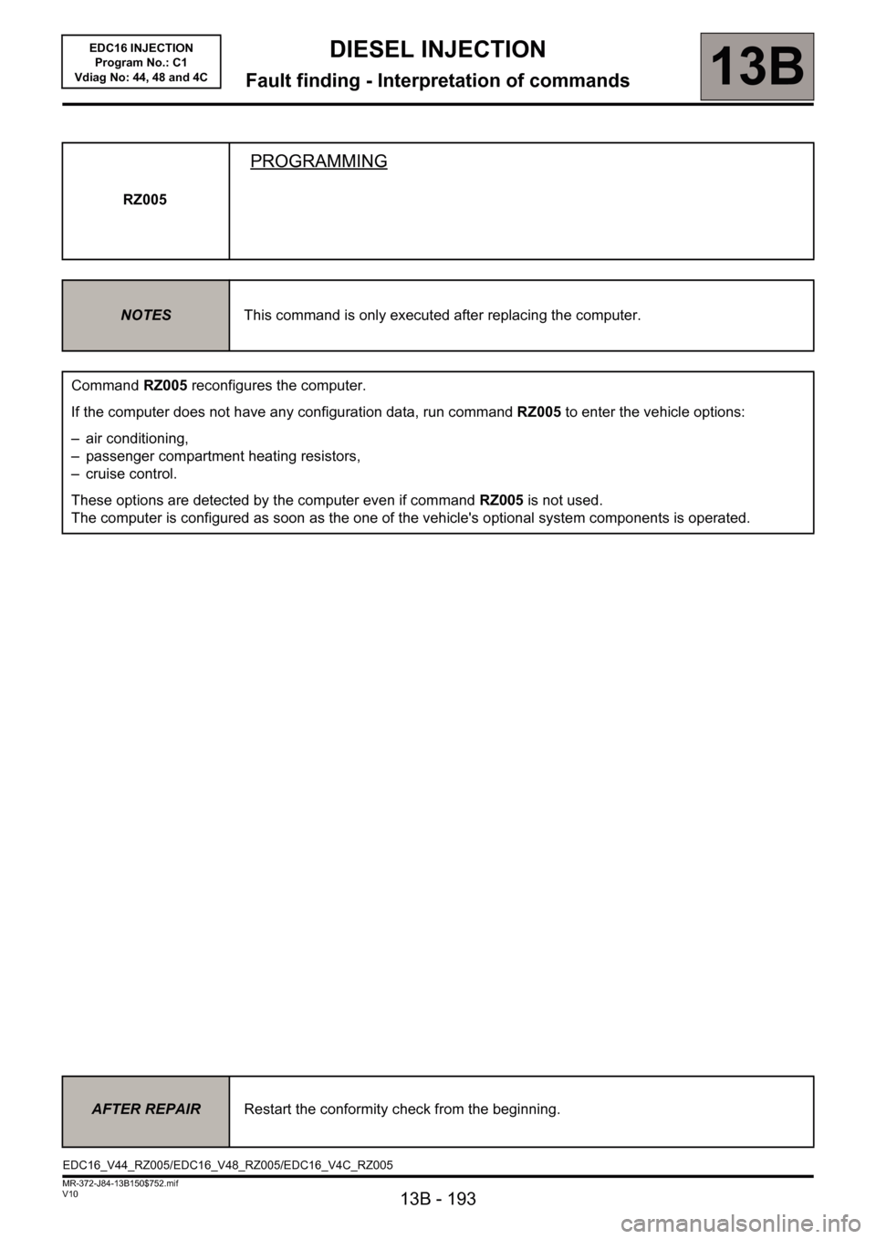
RZ005
PROGRAMMING
NOTESThis command is only executed after replacing the computer.
Command RZ005 reconfigures the computer.
If the computer does not have any configuration data, run command RZ005 to enter the vehicle options:
– air conditioning,
– passenger compartment heating resistors,
– cruise control.
These options are detected by the computer even if command RZ005 is not used.
The computer is configured as soon as the one of the vehicle's optional system components is operated.
AFTER REPAIRRestart the conformity check from the beginning.
EDC16_V44_RZ005/EDC16_V48_RZ005/EDC16_V4C_RZ005