battery RENAULT SCENIC 2011 J95 / 3.G Engine And Peripherals EDC16 Injection User Guide
[x] Cancel search | Manufacturer: RENAULT, Model Year: 2011, Model line: SCENIC, Model: RENAULT SCENIC 2011 J95 / 3.GPages: 236, PDF Size: 1.32 MB
Page 59 of 236
13B-59
DIESEL INJECTION
Fault finding - Interpretation of faults13B
V10 MR-372-J84-13B150$329.mif
EDC16 INJECTION
Program No.: C1
Vdiag No.: 44, 48 and 4C
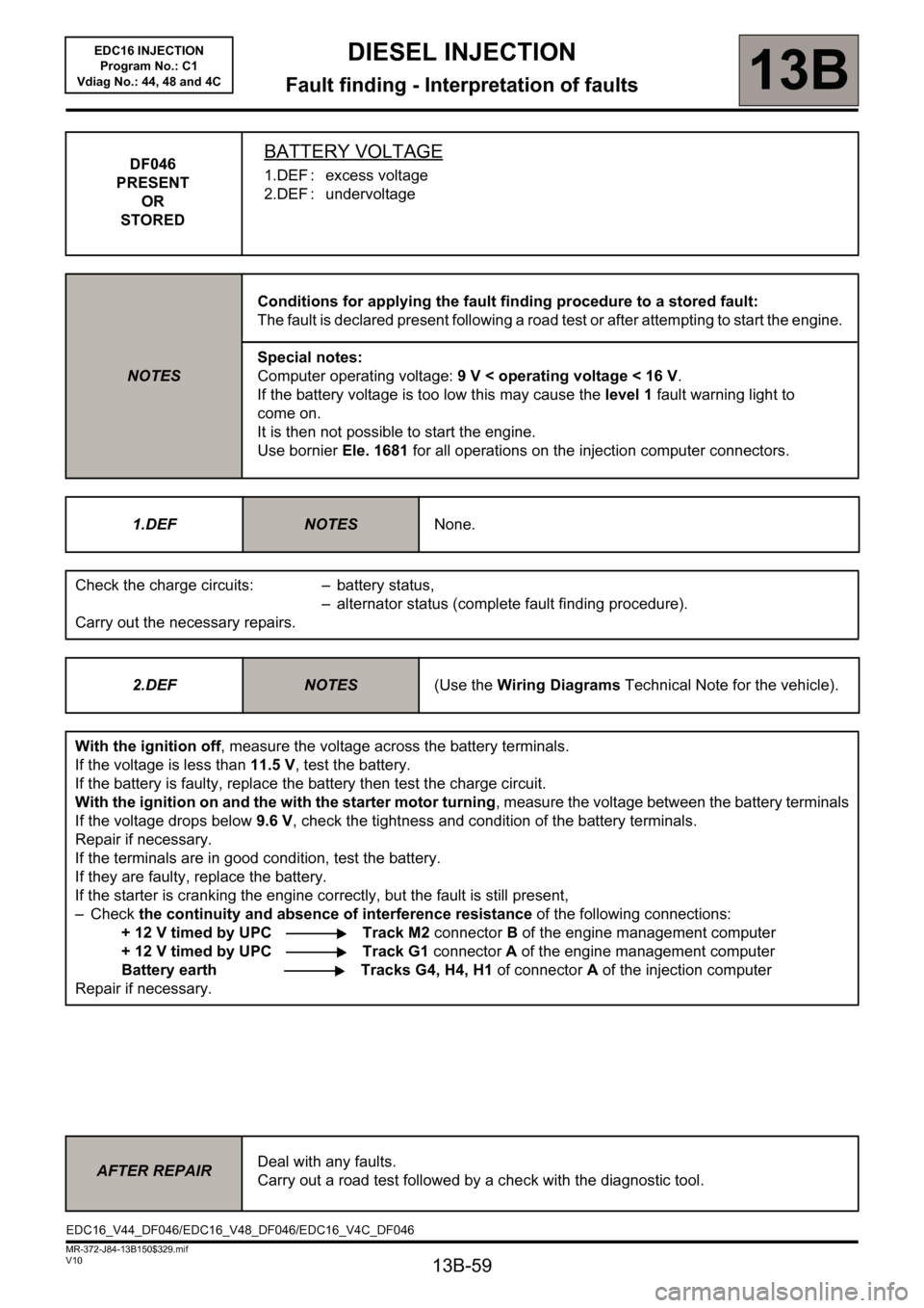
DF046
PRESENT
OR
STOREDBATTERY VOLTAGE
1.DEF : excess voltage
2.DEF : undervoltage
NOTESConditions for applying the fault finding procedure to a stored fault:
The fault is declared present following a road test or after attempting to start the engine.
Special notes:
Computer operating voltage: 9 V < operating voltage < 16 V.
If the battery voltage is too low this may cause the level 1 fault warning light to
come on.
It is then not possible to start the engine.
Use bornier Ele. 1681 for all operations on the injection computer connectors.
1.DEF
NOTESNone.
Check the charge circuits: – battery status,
– alternator status (complete fault finding procedure).
Carry out the necessary repairs.
2.DEF
NOTES(Use the Wiring Diagrams Technical Note for the vehicle).
With the ignition off, measure the voltage across the battery terminals.
If the voltage is less than 11.5 V, test the battery.
If the battery is faulty, replace the battery then test the charge circuit.
With the ignition on and the with the starter motor turning, measure the voltage between the battery terminals
If the voltage drops below 9.6 V, check the tightness and condition of the battery terminals.
Repair if necessary.
If the terminals are in good condition, test the battery.
If they are faulty, replace the battery.
If the starter is cranking the engine correctly, but the fault is still present,
–Check the continuity and absence of interference resistance of the following connections:
+ 12 V timed by UPC Track M2 connector B of the engine management computer
+ 12 V timed by UPC Track G1 connector A of the engine management computer
Battery earth Tracks G4, H4, H1 of connectorA of the injection computer
Repair if necessary.
AFTER REPAIRDeal with any faults.
Carry out a road test followed by a check with the diagnostic tool.
EDC16_V44_DF046/EDC16_V48_DF046/EDC16_V4C_DF046
Page 60 of 236
13B-60
DIESEL INJECTION
Fault finding - Interpretation of faults13B
V10 MR-372-J84-13B150$329.mif
EDC16 INJECTION
Program No.: C1
Vdiag No.: 44, 48 and 4C
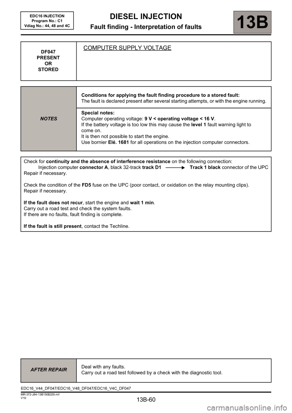
DF047
PRESENT
OR
STOREDCOMPUTER SUPPLY VOLTAGE
NOTESConditions for applying the fault finding procedure to a stored fault:
The fault is declared present after several starting attempts, or with the engine running.
Special notes:
Computer operating voltage: 9 V < operating voltage < 16 V.
If the battery voltage is too low this may cause the level 1 fault warning light to
come on.
It is then not possible to start the engine.
Use bornier Elé. 1681 for all operations on the injection computer connectors.
Check for continuity and the absence of interference resistance on the following connection:
Injection computer connector A, black 32-track track D1 Track 1 black connector of the UPC
Repair if necessary.
Check the condition of the FD5 fuse on the UPC (poor contact, or oxidation on the relay mounting clips).
Repair if necessary.
If the fault does not recur, start the engine and wait 1 min.
Carry out a road test and check the system faults.
If there are no faults, fault finding is complete.
If the fault is still present, contact the Techline.
AFTER REPAIRDeal with any faults.
Carry out a road test followed by a check with the diagnostic tool.
EDC16_V44_DF047/EDC16_V48_DF047/EDC16_V4C_DF047
Page 64 of 236
13B-64
DIESEL INJECTION
Fault finding - Interpretation of faults13B
V10 MR-372-J84-13B150$329.mif
EDC16 INJECTION
Program No.: C1
Vdiag No.: 44, 48 and 4C
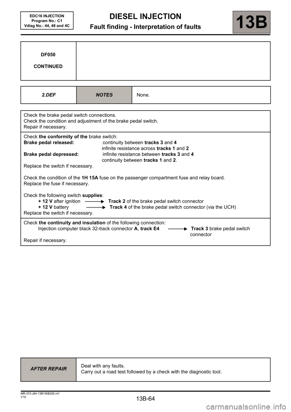
DF050
CONTINUED
2.DEF
NOTESNone.
Check the brake pedal switch connections.
Check the condition and adjustment of the brake pedal switch.
Repair if necessary.
Check the conformity of the brake switch:
Brake pedal released: continuity between tracks 3 and 4
infinite resistance across tracks 1 and 2
Brake pedal depressed: infinite resistance between tracks 3 and 4
continuity between tracks 1 and 2.
Replace the switch if necessary.
Check the condition of the 1H 15A fuse on the passenger compartment fuse and relay board.
Replace the fuse if necessary.
Check the following switch supplies:
+ 12 V after ignition Track 2 of the brake pedal switch connector
+ 12 V battery Track 4 of the brake pedal switch connector (via the UCH)
Replace the switch if necessary.
Check the continuity and insulation of the following connection:
Injection computer black 32-track connector A, track E4 Track 3 brake pedal switch
connector
Repair if necessary.
AFTER REPAIRDeal with any faults.
Carry out a road test followed by a check with the diagnostic tool.
Page 86 of 236
13B-86
DIESEL INJECTION
Fault finding - Interpretation of faults
13B
V10 MR-372-J84-13B150$376.mif
EDC16 INJECTION
Program No.: C1
Vdiag No.: 44, 48 and 4C
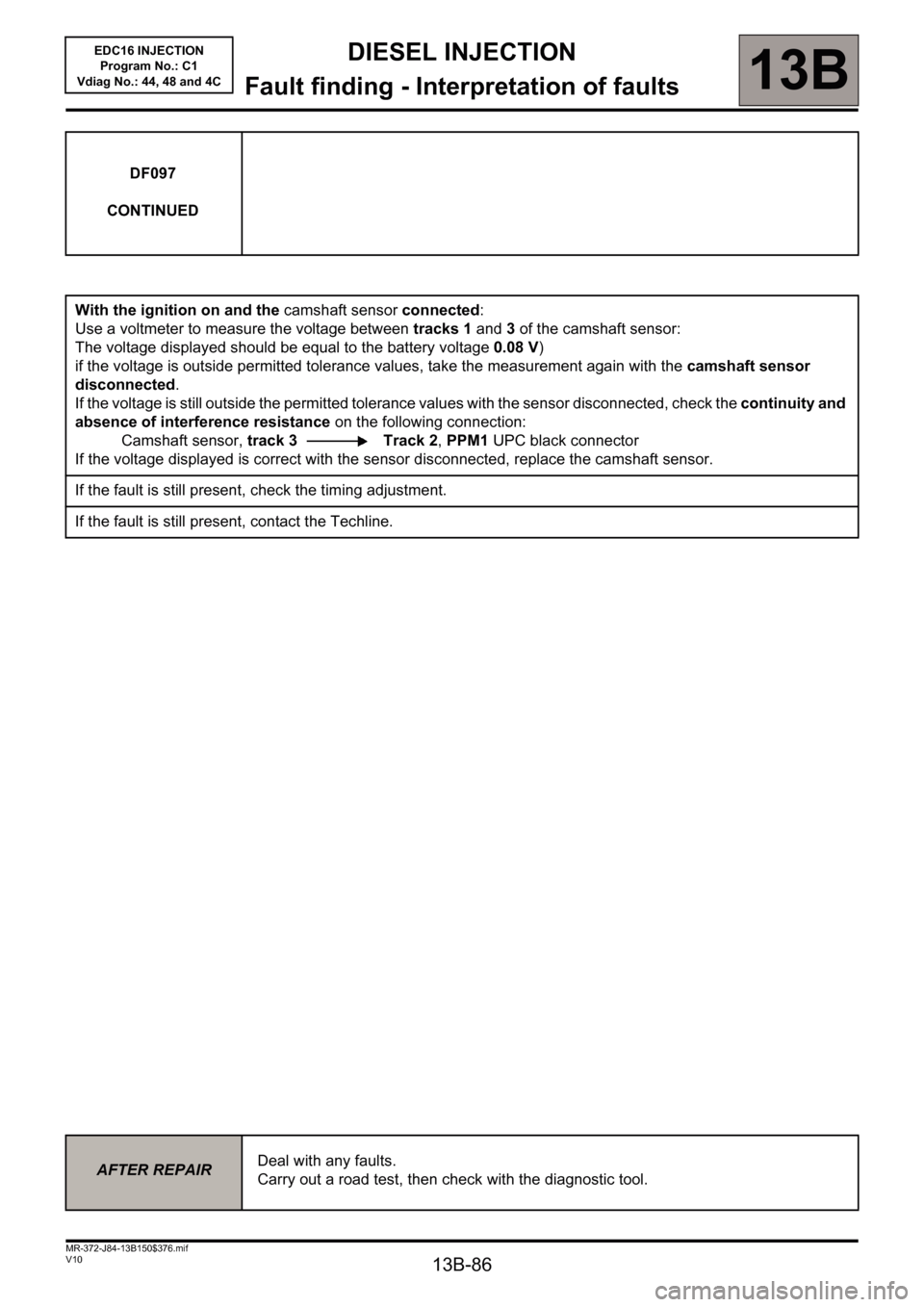
DF097
CONTINUED
With the ignition on and the camshaft sensor connected:
Use a voltmeter to measure the voltage between tracks 1 and 3 of the camshaft sensor:
The voltage displayed should be equal to the battery voltage 0.08 V)
if the voltage is outside permitted tolerance values, take the measurement again with the camshaft sensor
disconnected.
If the voltage is still outside the permitted tolerance values with the sensor disconnected, check the continuity and
absence of interference resistance on the following connection:
Camshaft sensor, track 3 Track 2, PPM1 UPC black connector
If the voltage displayed is correct with the sensor disconnected, replace the camshaft sensor.
If the fault is still present, check the timing adjustment.
If the fault is still present, contact the Techline.
AFTER REPAIRDeal with any faults.
Carry out a road test, then check with the diagnostic tool.
Page 93 of 236
13B-93
DIESEL INJECTION
Fault finding - Interpretation of faults
13B
V10 MR-372-J84-13B150$376.mif
EDC16 INJECTION
Program No.: C1
Vdiag No.: 44, 48 and 4C
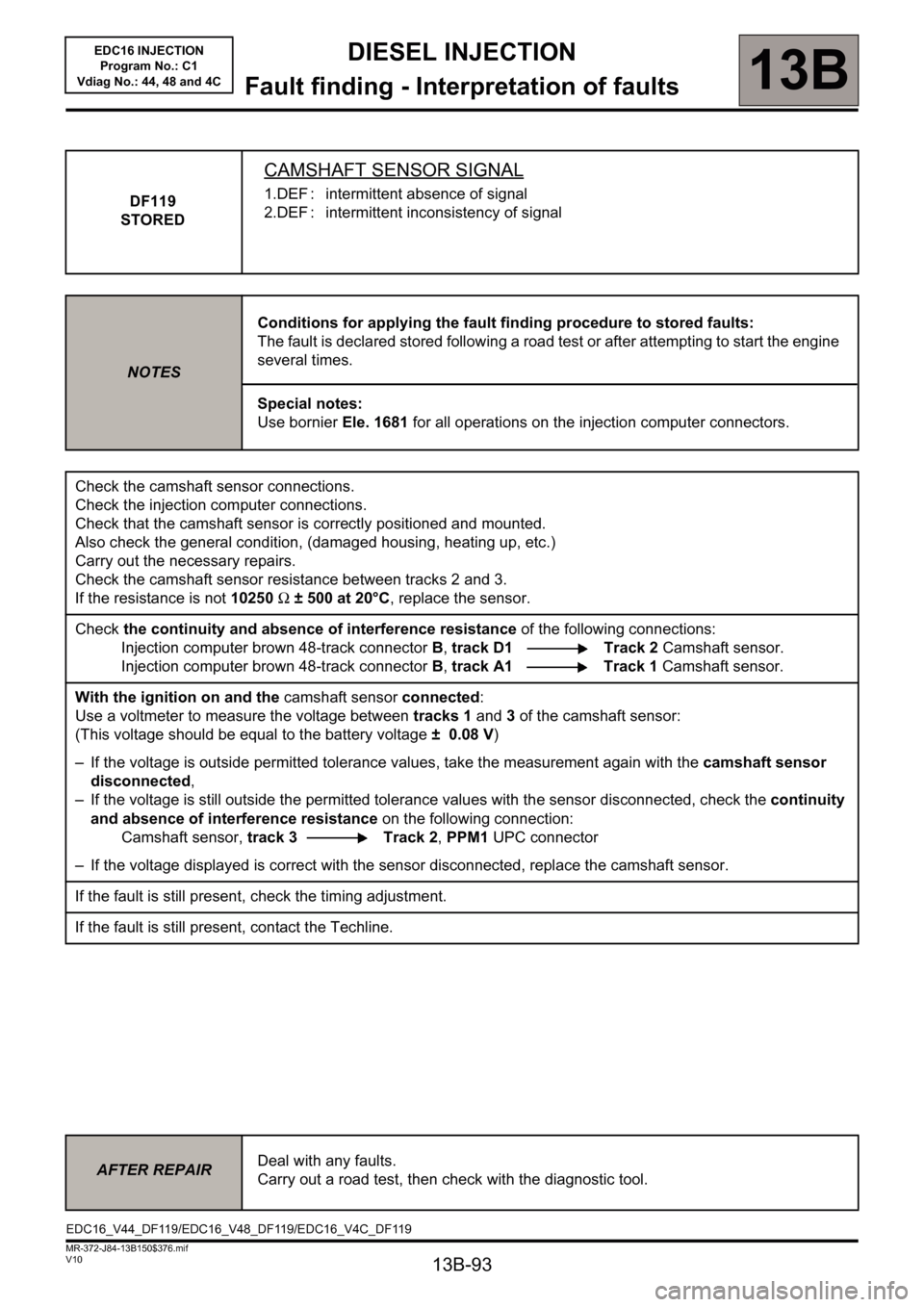
DF119
STORED
CAMSHAFT SENSOR SIGNAL
1.DEF : intermittent absence of signal
2.DEF : intermittent inconsistency of signal
NOTESConditions for applying the fault finding procedure to stored faults:
The fault is declared stored following a road test or after attempting to start the engine
several times.
Special notes:
Use bornier Ele. 1681 for all operations on the injection computer connectors.
Check the camshaft sensor connections.
Check the injection computer connections.
Check that the camshaft sensor is correctly positioned and mounted.
Also check the general condition, (damaged housing, heating up, etc.)
Carry out the necessary repairs.
Check the camshaft sensor resistance between tracks 2 and 3.
If the resistance is not 10250Ω ± 500 at 20°C, replace the sensor.
Check the continuity and absence of interference resistance of the following connections:
Injection computer brown 48-track connector B, track D1 Track 2 Camshaft sensor.
Injection computer brown 48-track connector B, track A1 Track 1 Camshaft sensor.
With the ignition on and the camshaft sensor connected:
Use a voltmeter to measure the voltage between tracks 1 and 3 of the camshaft sensor:
(This voltage should be equal to the battery voltage ± 0.08 V)
– If the voltage is outside permitted tolerance values, take the measurement again with the camshaft sensor
disconnected,
– If the voltage is still outside the permitted tolerance values with the sensor disconnected, check the continuity
and absence of interference resistance on the following connection:
Camshaft sensor, track 3 Track 2, PPM1 UPC connector
– If the voltage displayed is correct with the sensor disconnected, replace the camshaft sensor.
If the fault is still present, check the timing adjustment.
If the fault is still present, contact the Techline.
AFTER REPAIRDeal with any faults.
Carry out a road test, then check with the diagnostic tool.
EDC16_V44_DF119/EDC16_V48_DF119/EDC16_V4C_DF119
Page 101 of 236
13B-101
DIESEL INJECTION
Fault finding - Interpretation of faults
13B
V10 MR-372-J84-13B150$376.mif
EDC16 INJECTION
Program No.: C1
Vdiag No.: 44, 48 and 4C
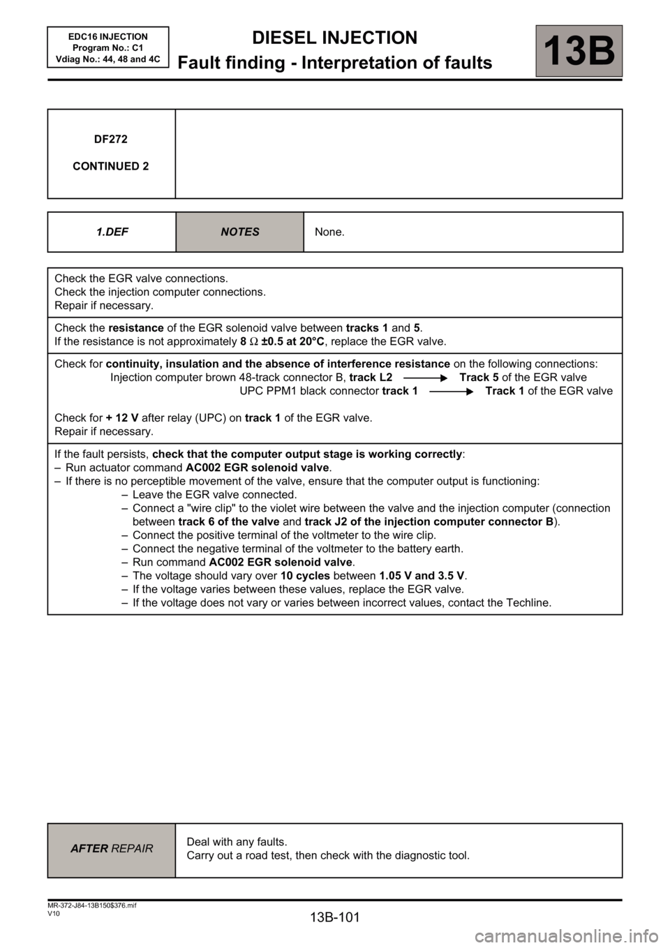
DF272
CONTINUED 2
1.DEF
NOTESNone.
Check the EGR valve connections.
Check the injection computer connections.
Repair if necessary.
Check the resistance of the EGR solenoid valve between tracks 1 and 5.
If the resistance is not approximately 8 Ω ±0.5 at 20°C, replace the EGR valve.
Check for continuity, insulation and the absence of interference resistance on the following connections:
Injection computer brown 48-track connector B, track L2 Track 5 of the EGR valve
UPC PPM1 black connector track 1 Track 1 of the EGR valve
Check for + 12 V after relay (UPC) on track 1 of the EGR valve.
Repair if necessary.
If the fault persists, check that the computer output stage is working correctly:
– Run actuator command AC002 EGR solenoid valve.
– If there is no perceptible movement of the valve, ensure that the computer output is functioning:
– Leave the EGR valve connected.
– Connect a "wire clip" to the violet wire between the valve and the injection computer (connection
between track 6 of the valve and track J2 of the injection computer connector B).
– Connect the positive terminal of the voltmeter to the wire clip.
– Connect the negative terminal of the voltmeter to the battery earth.
– Run command AC002 EGR solenoid valve.
– The voltage should vary over 10 cycles between 1.05 V and 3.5 V.
– If the voltage varies between these values, replace the EGR valve.
– If the voltage does not vary or varies between incorrect values, contact the Techline.
AFTER REPAIRDeal with any faults.
Carry out a road test, then check with the diagnostic tool.
Page 148 of 236
13B-148
DIESEL INJECTION
Fault finding - Interpretation of statuses13B
V10 MR-372-J84-13B150$564.mif
EDC16 INJECTION
Program No.: C1
Vdiag No.: 44, 48 and 4CDIESEL INJECTION
Fault finding - Interpretation of statuses
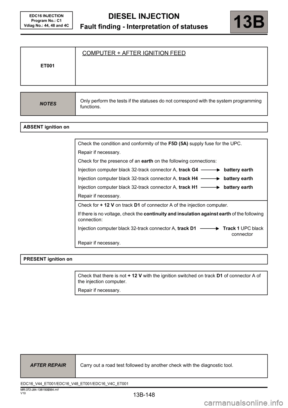
ET001
COMPUTER + AFTER IGNITION FEED
NOTESOnly perform the tests if the statuses do not correspond with the system programming
functions.
ABSENT ignition on
Check the condition and conformity of the F5D (5A) supply fuse for the UPC.
Repair if necessary.
Check for the presence of an earth on the following connections:
Injection computer black 32-track connector A, track G4 battery earth
Injection computer black 32-track connector A, track H4 battery earth
Injection computer black 32-track connector A, track H1 battery earth
Repair if necessary.
Check for + 12 V on trackD1 of connector A of the injection computer.
If there is no voltage, check the continuity and insulation against earth of the following
connection:
Injection computer black 32-track connector A, track D1 Track 1 UPC black
connector
Repair if necessary.
PRESENT ignition on
Check that there is not + 12 V with the ignition switched on trackD1 of connector A of
the injection computer.
Repair if necessary.
AFTER REPAIRCarry out a road test followed by another check with the diagnostic tool.
EDC16_V44_ET001/EDC16_V48_ET001/EDC16_V4C_ET001
MR-372-J84-13B150$564.mif
Page 152 of 236

13B-152
DIESEL INJECTION
Fault finding - Interpretation of statuses13B
V10 MR-372-J84-13B150$564.mif
EDC16 INJECTION
Program No.: C1
Vdiag No.: 44, 48 and 4C
ET014
FAN ASSEMBLY 1 CHECK
NOTESOnly perform the tests if the statuses do not correspond with the system programming
functions.
Note: Status ET022 Low-speed engine fan request and status ET014 Engine fan assembly check 1 change
their status at the same time.
RUNNING
The low-speed fan assembly is supplied in three scenarios:
– the engine coolant temperature is above 89°C,
– the air conditioning is operating,
– the injection computer has system faults that could lead to the engine overheating.
When the low-speed fan assembly is supplied:
– status ET014 changes to RUNNING
– status ET022 low-speed engine fan request changes to ACTIVE.
In the event that the low-speed engine fan does not work, refer to the UPC fault finding note.
STOPPED
The low-speed fan assembly stops when:
– the engine coolant temperature is below 89°C,
– no air conditioning request made by the driver.
IMPORTANT!WARNING
If the UPC does not detect the injection computer frames, the low-speed engine
fan assembly is supplied until the battery is completely discharged.
In the event that the low-speed engine fan assembly is defective, the high-speed
engine fan assembly will then be activated.
AFTER REPAIRCarry out a road test followed by another check with the diagnostic tool.
EDC16_V44_ET014/EDC16_V48_ET014/EDC16_V4C_ET014
Page 153 of 236
13B-153
DIESEL INJECTION
Fault finding - Interpretation of statuses13B
V10 MR-372-J84-13B150$564.mif
EDC16 INJECTION
Program No.: C1
Vdiag No.: 44, 48 and 4C
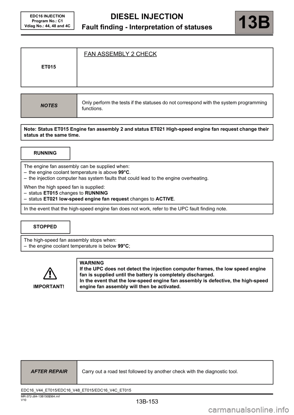
ET015
FAN ASSEMBLY 2 CHECK
NOTESOnly perform the tests if the statuses do not correspond with the system programming
functions.
Note: Status ET015 Engine fan assembly 2 and status ET021 High-speed engine fan request change their
status at the same time.
RUNNING
The engine fan assembly can be supplied when:
– the engine coolant temperature is above 99°C.
– the injection computer has system faults that could lead to the engine overheating.
When the high speed fan is supplied:
– status ET015 changes to RUNNING
– status ET021 low-speed engine fan request changes to ACTIVE.
In the event that the high-speed engine fan does not work, refer to the UPC fault finding note.
STOPPED
The high-speed fan assembly stops when:
– the engine coolant temperature is below 99°C;
IMPORTANT!WARNING
If the UPC does not detect the injection computer frames, the low speed engine
fan is supplied until the battery is completely discharged.
In the event that the low-speed engine fan assembly is defective, the high-speed
engine fan assembly will then be activated.
AFTER REPAIRCarry out a road test followed by another check with the diagnostic tool.
EDC16_V44_ET015/EDC16_V48_ET015/EDC16_V4C_ET015
Page 154 of 236
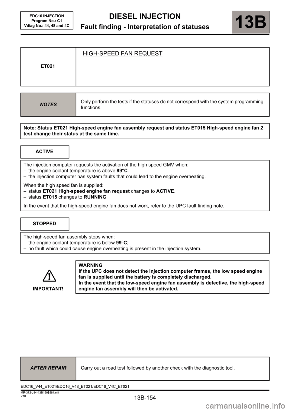
13B-154
DIESEL INJECTION
Fault finding - Interpretation of statuses13B
V10 MR-372-J84-13B150$564.mif
EDC16 INJECTION
Program No.: C1
Vdiag No.: 44, 48 and 4C
ET021
HIGH-SPEED FAN REQUEST
NOTESOnly perform the tests if the statuses do not correspond with the system programming
functions.
Note: Status ET021 High-speed engine fan assembly request and status ET015 High-speed engine fan 2
test change their status at the same time.
ACTIVE
The injection computer requests the activation of the high speed GMV when:
– the engine coolant temperature is above 99°C.
– the injection computer has system faults that could lead to the engine overheating.
When the high speed fan is supplied:
– status ET021 High-speed engine fan request changes to ACTIVE.
– status ET015 changes to RUNNING
In the event that the high-speed engine fan does not work, refer to the UPC fault finding note.
STOPPED
The high-speed fan assembly stops when:
– the engine coolant temperature is below 99°C;
– no fault which could cause engine overheating is present in the injection system.
IMPORTANT!WARNING
If the UPC does not detect the injection computer frames, the low speed engine
fan is supplied until the battery is completely discharged.
In the event that the low-speed engine fan assembly is defective, the high-speed
engine fan assembly will then be activated.
AFTER REPAIRCarry out a road test followed by another check with the diagnostic tool.
EDC16_V44_ET021/EDC16_V48_ET021/EDC16_V4C_ET021