battery RENAULT SCENIC 2011 J95 / 3.G Engine And Peripherals EDC16 Injection Owner's Manual
[x] Cancel search | Manufacturer: RENAULT, Model Year: 2011, Model line: SCENIC, Model: RENAULT SCENIC 2011 J95 / 3.GPages: 236, PDF Size: 1.32 MB
Page 155 of 236
13B-155
DIESEL INJECTION
Fault finding - Interpretation of statuses13B
V10 MR-372-J84-13B150$564.mif
EDC16 INJECTION
Program No.: C1
Vdiag No.: 44, 48 and 4C
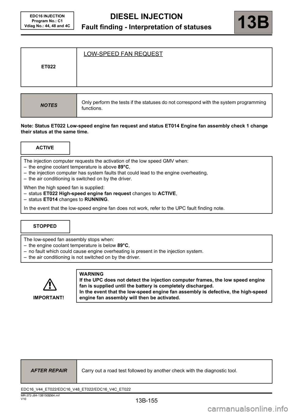
Note: Status ET022 Low-speed engine fan request and status ET014 Engine fan assembly check 1 change
their status at the same time.ET022
LOW-SPEED FAN REQUEST
NOTESOnly perform the tests if the statuses do not correspond with the system programming
functions.
ACTIVE
The injection computer requests the activation of the low speed GMV when:
– the engine coolant temperature is above 89°C,
– the injection computer has system faults that could lead to the engine overheating,
– the air conditioning is switched on by the driver.
When the high speed fan is supplied:
– status ET022 High-speed engine fan request changes to ACTIVE,
– status ET014 changes to RUNNING.
In the event that the low-speed engine fan does not work, refer to the UPC fault finding note.
STOPPED
The low-speed fan assembly stops when:
– the engine coolant temperature is below 89°C,
– no fault which could cause engine overheating is present in the injection system.
– the air conditioning is not switched on by the driver.
IMPORTANT!WARNING
If the UPC does not detect the injection computer frames, the low speed engine
fan is supplied until the battery is completely discharged.
In the event that the low-speed engine fan assembly is defective, the high-speed
engine fan assembly will then be activated.
AFTER REPAIRCarry out a road test followed by another check with the diagnostic tool.
EDC16_V44_ET022/EDC16_V48_ET022/EDC16_V4C_ET022
Page 194 of 236
13B - 194
DIESEL INJECTION
Fault finding - Interpretation of commands13B
V10 MR-372-J84-13B150$752.mif
EDC16 INJECTION
Program No.: C1
Vdiag No: 44, 48 and 4C
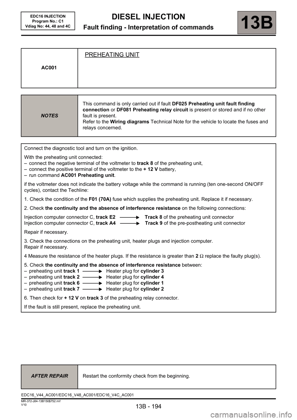
AC001
PREHEATING UNIT
NOTESThis command is only carried out if fault DF025 Preheating unit fault finding
connection or DF081 Preheating relay circuit is present or stored and if no other
fault is present.
Refer to the Wiring diagrams Technical Note for the vehicle to locate the fuses and
relays concerned.
Connect the diagnostic tool and turn on the ignition.
With the preheating unit connected:
– connect the negative terminal of the voltmeter to track 8 of the preheating unit,
– connect the positive terminal of the voltmeter to the + 12 V battery,
– run command AC001 Preheating unit.
if the voltmeter does not indicate the battery voltage while the command is running (ten one-second ON/OFF
cycles), contact the Techline:
1. Check the condition of theF01 (70A) fuse which supplies the preheating unit. Replace it if necessary.
2. Check the continuity and the absence of interference resistance on the following connections:
Injection computer connector C, track E2 Track 8 of the preheating unit connector
Injection computer connector C, track A4 Track 9 of the pre-postheating unit connector
Repair if necessary.
3. Check the connections on the preheating unit, heater plugs and injection computer.
Repair if necessary.
4 Measure the resistance of the heater plugs. If the resistance is greater than 2Ω replace the faulty plug(s).
5. Check the continuity and the absence of interference resistance between:
– preheating unit track 1Heater plug for cylinder 3
– preheating unit track 2Heater plug for cylinder 4
– preheating unit track 6Heater plug for cylinder 1
– preheating unit track 7Heater plug for cylinder 2
6. Then check for +12V on track 3 of the preheating relay connector.
If the fault is still present, replace the preheating unit.
AFTER REPAIRRestart the conformity check from the beginning.
EDC16_V44_AC001/EDC16_V48_AC001/EDC16_V4C_AC001
Page 196 of 236
13B - 196
DIESEL INJECTION
Fault finding - Interpretation of commands13B
V10 MR-372-J84-13B150$752.mif
EDC16 INJECTION
Program No.: C1
Vdiag No: 44, 48 and 4C
AC002
CONTINUED
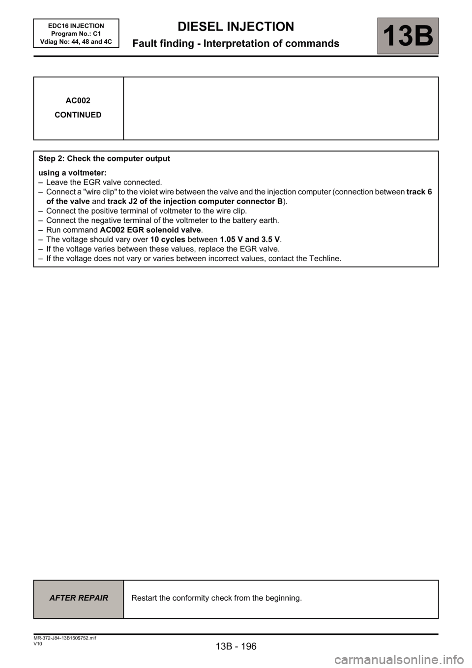
Step 2: Check the computer output
using a voltmeter:
– Leave the EGR valve connected.
– Connect a "wire clip" to the violet wire between the valve and the injection computer (connection between track 6
of the valve and track J2 of the injection computer connector B).
– Connect the positive terminal of voltmeter to the wire clip.
– Connect the negative terminal of the voltmeter to the battery earth.
– Run command AC002 EGR solenoid valve.
– The voltage should vary over 10 cycles between 1.05 V and 3.5 V.
– If the voltage varies between these values, replace the EGR valve.
– If the voltage does not vary or varies between incorrect values, contact the Techline.
AFTER REPAIRRestart the conformity check from the beginning.
Page 198 of 236
13B - 198
DIESEL INJECTION
Fault finding - Interpretation of commands13B
V10 MR-372-J84-13B150$752.mif
EDC16 INJECTION
Program No.: C1
Vdiag No: 44, 48 and 4C
* Opening Cyclic Ratio. AC004
CONTINUED
Turbocharger control circuit check (continued)
4) Turbocharging operation check:
a) Connect vacuum pump to the hoses connected to the turbocharger control diaphragm,
– Apply a vacuum pressure of 800 mbar:
If there is a leak, replace the turbocharger (diaphragm included).
b) Check the movement of the control rod (See MR 364, 12B, Mechanical, Turbocharging).
If the control rod is sticking, replace the turbocharger.
c) Engine cold and switched off:
– Remove the turbocharger inlet duct and check that the compressor turns freely on the axis.
d) If the fault is still present:
– Check that the exhaust manifold is not leaking.
– Check that the exhaust is not blocked.
Carry out the necessary repairs.
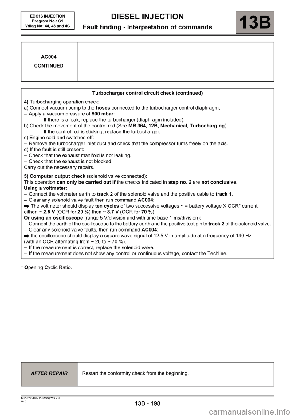
5) Computer output check (solenoid valve connected):
This operation can only be carried out if the checks indicated in step no. 2 are not conclusive.
Using a voltmeter:
– Connect the voltmeter earth to track 2 of the solenoid valve and the positive cable to track 1.
– Clear any solenoid valve fault then run command AC004:
The voltmeter should display ten cycles of two successive voltages ~ =battery voltage X OCR* current.
either: ~2.5V (OCR for 20 %) then ~8.7V (OCR for 70 %).
Or using an oscilloscope (range 5 V/division and with time base 1 ms/division):
– Connect the earth of the oscilloscope to the battery earth and the positive test pin to track 2 of the solenoid valve.
– Clear any solenoid valve faults, then run command AC004:
the oscilloscope should display a square wave signal of 12.5 V in amplitude at a frequency of 140 Hz
(with an OCR alternating from ~ 20 to ~ 70 %).
– If the measurement is correct, replace the solenoid valve.
– If the measurement does not show any control or continuous voltage, contact the Techline.
AFTER REPAIRRestart the conformity check from the beginning.
Page 199 of 236
13B - 199
DIESEL INJECTION
Fault finding - Interpretation of commands13B
V10 MR-372-J84-13B150$752.mif
EDC16 INJECTION
Program No.: C1
Vdiag No: 44, 48 and 4C
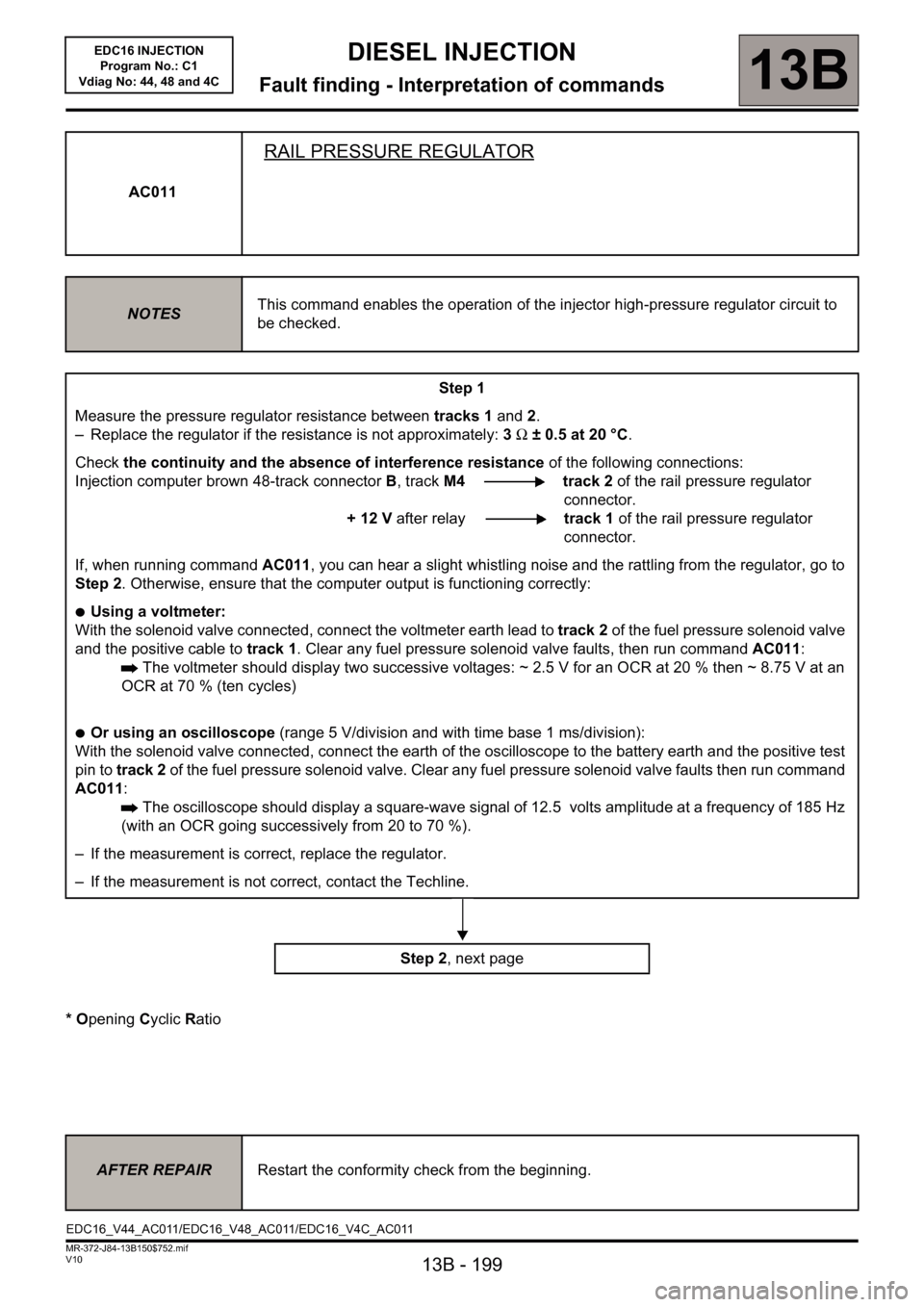
* Opening Cyclic Ratio AC011
RAIL PRESSURE REGULATOR
NOTESThis command enables the operation of the injector high-pressure regulator circuit to
be checked.
Step 1
Measure the pressure regulator resistance between tracks 1 and 2.
– Replace the regulator if the resistance is not approximately: 3Ω ± 0.5 at 20 °C.
Check the continuity and the absence of interference resistance of the following connections:
Injection computer brown 48-track connectorB, trackM4 track 2 of the rail pressure regulator
connector.
+ 12 V after relaytrack 1 of the rail pressure regulator
connector.
If, when running command AC011, you can hear a slight whistling noise and the rattling from the regulator, go to
Step 2. Otherwise, ensure that the computer output is functioning correctly:
●Using a voltmeter:
With the solenoid valve connected, connect the voltmeter earth lead to track 2 of the fuel pressure solenoid valve
and the positive cable to track 1. Clear any fuel pressure solenoid valve faults, then run command AC011:
The voltmeter should display two successive voltages: ~ 2.5 V for an OCR at 20 % then ~ 8.75 V at an
OCR at 70 % (ten cycles)
●Or using an oscilloscope (range 5 V/division and with time base 1 ms/division):
With the solenoid valve connected, connect the earth of the oscilloscope to the battery earth and the positive test
pin to track 2 of the fuel pressure solenoid valve. Clear any fuel pressure solenoid valve faults then run command
AC011:
The oscilloscope should display a square-wave signal of 12.5 volts amplitude at a frequency of 185 Hz
(with an OCR going successively from 20 to 70 %).
– If the measurement is correct, replace the regulator.
– If the measurement is not correct, contact the Techline.
Step 2, next page
AFTER REPAIRRestart the conformity check from the beginning.
EDC16_V44_AC011/EDC16_V48_AC011/EDC16_V4C_AC011
Page 206 of 236
13B-206
MR-372-J84-13B150$846.mif
V10
DIESEL INJECTION
Fault finding - Fault finding chart13B
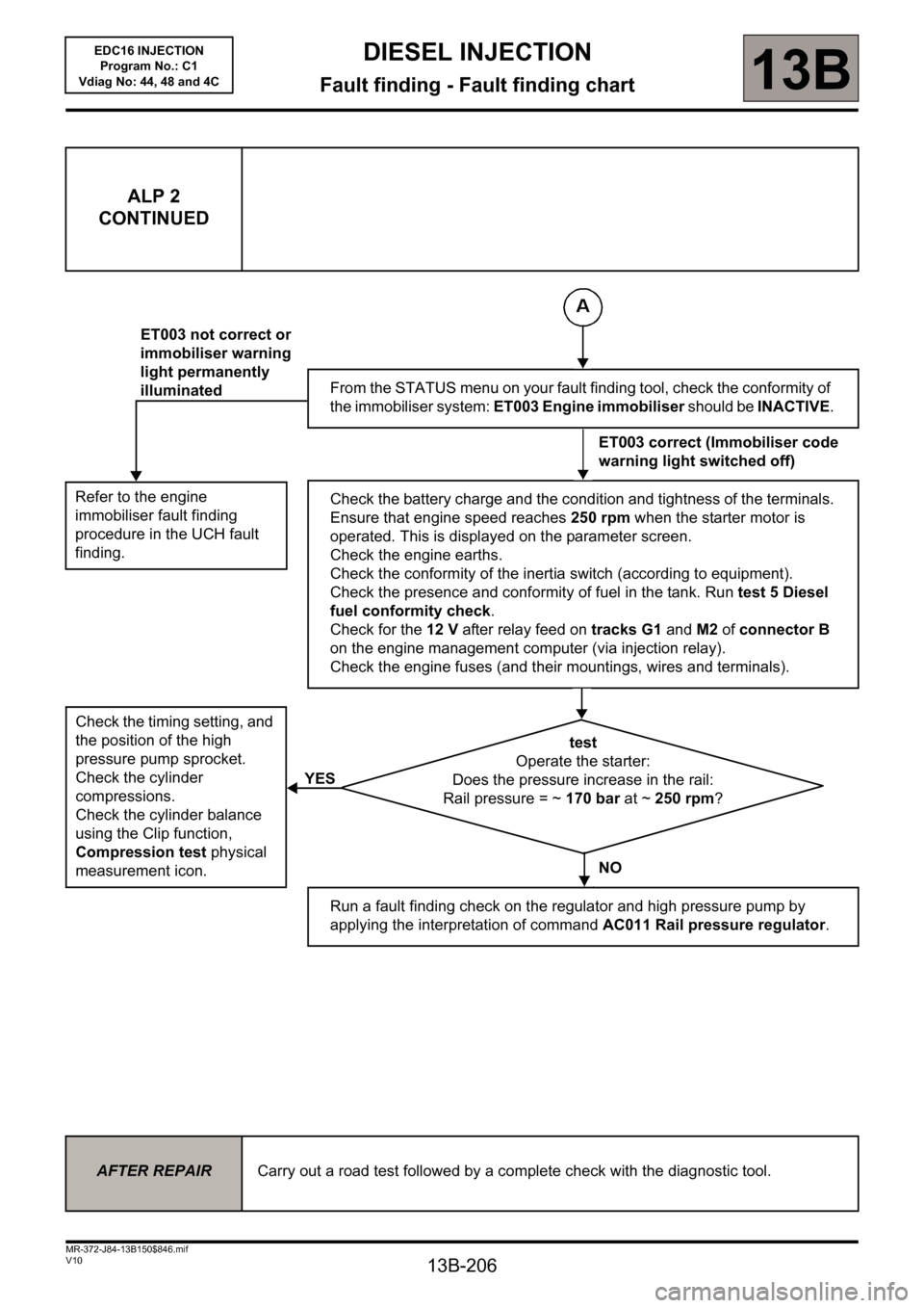
ALP 2
CONTINUED
Refer to the engine
immobiliser fault finding
procedure in the UCH fault
finding.
Check the timing setting, and
the position of the high
pressure pump sprocket.
Check the cylinder
compressions.
Check the cylinder balance
using the Clip function,
Compression test physical
measurement icon.
ET003 not correct or
immobiliser warning
light permanently
illuminated
YESFrom the STATUS menu on your fault finding tool, check the conformity of
the immobiliser system: ET003 Engine immobiliser should be INACTIVE.
ET003 correct (Immobiliser code
warning light switched off)
Check the battery charge and the condition and tightness of the terminals.
Ensure that engine speed reaches 250 rpm when the starter motor is
operated. This is displayed on the parameter screen.
Check the engine earths.
Check the conformity of the inertia switch (according to equipment).
Check the presence and conformity of fuel in the tank. Run test 5 Diesel
fuel conformity check.
Check for the 12 V after relay feed on tracks G1 and M2 of connector B
on the engine management computer (via injection relay).
Check the engine fuses (and their mountings, wires and terminals).
test
Operate the starter:
Does the pressure increase in the rail:
Rail pressure = ~ 170 bar at ~ 250 rpm?
NO
Run a fault finding check on the regulator and high pressure pump by
applying the interpretation of command AC011 Rail pressure regulator.
AFTER REPAIRCarry out a road test followed by a complete check with the diagnostic tool.
EDC16 INJECTION
Program No.: C1
Vdiag No: 44, 48 and 4C
Page 208 of 236
13B-208
MR-372-J84-13B150$846.mif
V10
DIESEL INJECTION
Fault finding - Fault finding chart13B
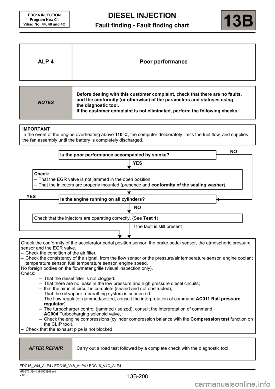
ALP 4 Poor performance
NOTESBefore dealing with this customer complaint, check that there are no faults,
and the conformity (or otherwise) of the parameters and statuses using
the diagnostic tool.
If the customer complaint is not eliminated, perform the following checks.
IMPORTANT
In the event of the engine overheating above 11 0 ° C, the computer deliberately limits the fuel flow, and supplies
the fan assembly until the battery is completely discharged.
Is the poor performance accompanied by smoke?
YES
Check:
– That the EGR valve is not jammed in the open position.
– That the injectors are properly mounted (presence and conformity of the sealing washer).
Is the engine running on all cylinders?
NO
Check that the injectors are operating correctly. (See Test 1)
If the fault is still present
Check the conformity of the accelerator pedal position sensor, the brake pedal sensor, the atmospheric pressure
sensor and the EGR valve.
– Check the condition of the air filter.
– Check the consistency of the signal: from the flow sensor or the pressure/air temperature sensor, engine coolant
temperature sensor, fuel temperature sensor, engine speed.
No foreign bodies on the flowmeter grille (visual inspection only).
Check:
– That the diesel filter is not clogged.
– That there are no leaks in the low pressure and high pressure diesel circuits;
– that the air inlet circuit is complete (sealed and not obstructed),
– That the oil vapour rebreathing system is connected.
– The flow regulator (jammed/seized, consult the interpretation of command AC011 Rail pressure
regulator).
– The turbocharger control (jammed / seized), consult the interpretation of command
AC004Turbocharging solenoid valve,
– Check the engine compressions (cylinder compression balance with the Compression test function on
the CLIP tool).
– Check that the exhaust pipe is not blocked.
NO
YES
AFTER REPAIRCarry out a road test followed by a complete check with the diagnostic tool.
EDC16_V44_ALP4 / EDC16_V48_ALP4 / EDC16_V4C_ALP4
EDC16 INJECTION
Program No.: C1
Vdiag No: 44, 48 and 4C
Page 236 of 236
13B-236
DIESEL INJECTION
Fault finding - Glossary13B
V10 MR-372-J84-13B150$940.mif
EDC16 INJECTION
Program No.: C1
Vdiag No: 44, 48 and 4CDIESEL INJECTION
Fault finding - Glossary
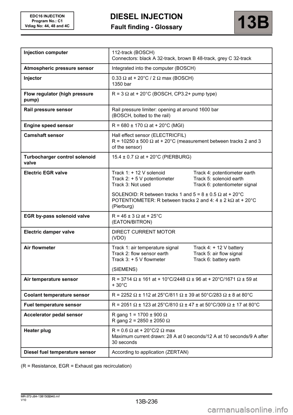
(R = Resistance, EGR = Exhaust gas recirculation)Injection computer112-track (BOSCH)
Connectors: black A 32-track, brown B 48-track, grey C 32-track
Atmospheric pressure sensorIntegrated into the computer (BOSCH)
Injector0.33Ω at + 20°C / 2Ω max (BOSCH)
1350 bar
Flow regulator (high pressure
pump)R= 3Ω at + 20°C (BOSCH, CP3.2+ pump type)
Rail pressure sensorRail pressure limiter: opening at around 1600 bar
(BOSCH, bolted to the rail)
Engine speed sensorR = 680 ± 170Ω at + 20°C (MGI)
Camshaft sensorHall effect sensor (ELECTRICFIL)
R = 10250 ± 500Ω at + 20°C (measurement between tracks 2 and 3
of the sensor)
Turbocharger control solenoid
valve15.4 ± 0.7Ω at + 20°C (PIERBURG)
Electric EGR valveTrack 1: + 12 V solenoid
Track 2: + 5 V potentiometer
Track 3: Not usedTrack 4: potentiometer earth
Track 5: solenoid earth
Track 6: potentiometer signal
SOLENOID: R between tracks 1 and 5 = 8 ± 0.5Ω at + 20°C
POTENTIOMETER: R between tracks 2 and 4: 4 ± 2 kΩ at + 20°C
(Pierburg)
EGR by-pass solenoid valveR= 46 ±3Ω at + 25°C
(EATON/BITRON)
Electric damper valveDIRECT CURRENT MOTOR
(VDO)
Air flowmeterTrack 1: air temperature signal
Track 2: flow sensor earth
Track 3: + 5 V flowmeterTrack 4: + 12 V battery
Track 5: air flow signal
Track 6: battery earth
(SIEMENS)
Air temperature sensorR = 3714Ω ± 161 at + 10°C/2448Ω ± 96 at + 20°C/1671Ω ± 59 at
+30°C
Coolant temperature sensorR = 2252Ω ± 112 at 25°C/811Ω ± 39 at 50°C/283Ω ±8 at 80°C
Fuel temperature sensorR = 2051Ω ± 123 at 25°C/810Ω ± 47 ± at 50°C/309Ω ± 17 at 80°C
Accelerator pedal sensorR gang 1 = 1700 ± 900Ω
R gang 2 = 2850 ± 2050Ω
Heater plugR= 0.6Ω at + 20°C/2Ω max
Maximum current drawn: 28 A at 0 seconds/12 A at 10 seconds/9 A after
30 seconds
Diesel fuel temperature sensorAccording to application (ZERTAN)
MR-372-J84-13B150$940.mif