check RENAULT SCENIC 2011 J95 / 3.G Engine And Peripherals EDC16 Injection User Guide
[x] Cancel search | Manufacturer: RENAULT, Model Year: 2011, Model line: SCENIC, Model: RENAULT SCENIC 2011 J95 / 3.GPages: 236, PDF Size: 1.32 MB
Page 21 of 236
13B - 21
DIESEL INJECTION
Fault finding - Replacement of components13B
V10 MR-372-J84-13B150$188.mif
EDC16 INJECTION
Program No.: C1
Vdiag No.: 44, 48 and 4C
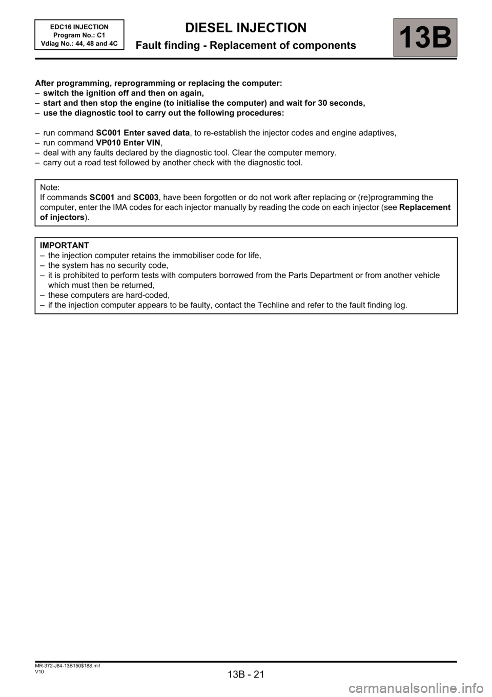
After programming, reprogramming or replacing the computer:
–switch the ignition off and then on again,
–start and then stop the engine (to initialise the computer) and wait for 30 seconds,
–use the diagnostic tool to carry out the following procedures:
– run command SC001 Enter saved data, to re-establish the injector codes and engine adaptives,
– run command VP010 Enter VIN,
– deal with any faults declared by the diagnostic tool. Clear the computer memory.
– carry out a road test followed by another check with the diagnostic tool.
Note:
If commands SC001 and SC003, have been forgotten or do not work after replacing or (re)programming the
computer, enter the IMA codes for each injector manually by reading the code on each injector (see Replacement
of injectors).
IMPORTANT
– the injection computer retains the immobiliser code for life,
– the system has no security code,
– it is prohibited to perform tests with computers borrowed from the Parts Department or from another vehicle
which must then be returned,
– these computers are hard-coded,
– if the injection computer appears to be faulty, contact the Techline and refer to the fault finding log.
Page 22 of 236
13B - 22
DIESEL INJECTION
Fault finding - Replacement of components13B
V10 MR-372-J84-13B150$188.mif
EDC16 INJECTION
Program No.: C1
Vdiag No.: 44, 48 and 4C
REPLACING THE INJECTORS
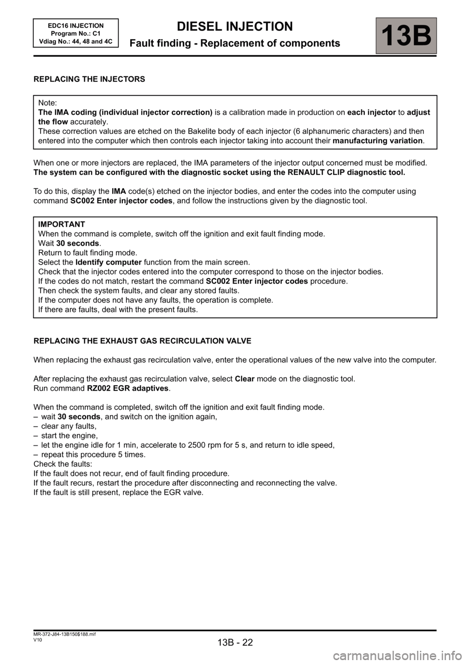
When one or more injectors are replaced, the IMA parameters of the injector output concerned must be modified.
The system can be configured with the diagnostic socket using the RENAULT CLIP diagnostic tool.
To do this, display the IMA code(s) etched on the injector bodies, and enter the codes into the computer using
command SC002 Enter injector codes, and follow the instructions given by the diagnostic tool.
REPLACING THE EXHAUST GAS RECIRCULATION VALVE
When replacing the exhaust gas recirculation valve, enter the operational values of the new valve into the computer.
After replacing the exhaust gas recirculation valve, select Clear mode on the diagnostic tool.
Run command RZ002 EGR adaptives.
When the command is completed, switch off the ignition and exit fault finding mode.
–wait 30 seconds, and switch on the ignition again,
– clear any faults,
– start the engine,
– let the engine idle for 1 min, accelerate to 2500 rpm for 5 s, and return to idle speed,
– repeat this procedure 5 times.
Check the faults:
If the fault does not recur, end of fault finding procedure.
If the fault recurs, restart the procedure after disconnecting and reconnecting the valve.
If the fault is still present, replace the EGR valve. Note:
The IMA coding (individual injector correction) is a calibration made in production on each injector to adjust
the flow accurately.
These correction values are etched on the Bakelite body of each injector (6 alphanumeric characters) and then
entered into the computer which then controls each injector taking into account their manufacturing variation.
IMPORTANT
When the command is complete, switch off the ignition and exit fault finding mode.
Wait 30 seconds.
Return to fault finding mode.
Select the Identify computer function from the main screen.
Check that the injector codes entered into the computer correspond to those on the injector bodies.
If the codes do not match, restart the command SC002 Enter injector codes procedure.
Then check the system faults, and clear any stored faults.
If the computer does not have any faults, the operation is complete.
If there are faults, deal with the present faults.
Page 26 of 236
13B-26
DIESEL INJECTION
Fault finding - Interpretation of faults13B
V10 MR-372-J84-13B150$282.mif
EDC16 INJECTION
Program No.: C1
Vdiag No.: 44, 48 and 4CDIESEL INJECTION
Fault finding - Interpretation of faults
DF001
PRESENT
OR
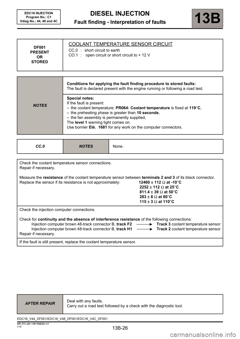
STOREDCOOLANT TEMPERATURE SENSOR CIRCUIT
CC.0 : short circuit to earth
CO.1 : open circuit or short circuit to + 12 V
NOTESConditions for applying the fault finding procedure to stored faults:
The fault is declared present with the engine running or following a road test.
Special notes:
If the fault is present:
– the coolant temperature: PR064: Coolant temperature is fixed at 119°C,
– the preheating phase is greater than 10 seconds,
– the fan assembly is permanently supplied,
The level 1 warning light comes on.
Use bornier Elé. 1681 for any work on the computer connectors.
CC.0
NOTESNone.
Check the coolant temperature sensor connections.
Repair if necessary.
Measure the resistance of the coolant temperature sensor between terminals 2 and 3 of its black connector.
Replace the sensor if its resistance is not approximately: 12460±112Ω at -10°C
2252±112Ω at 25°C
811.4±39Ω at 50°C
283±8Ω at 80°C
115±3Ω at 110°C
Check the injection computer connections.
Check for continuity and the absence of interference resistance of the following connections:
Injection computer brown 48-track connector B, track F2 Track 3 coolant temperature sensor
Injection computer brown 48-track connector B, track H1 Track 2 coolant temperature sensor
Repair if necessary.
If the fault is still present, replace the coolant temperature sensor.
AFTER REPAIRDeal with any faults.
Carry out a road test followed by a check with the diagnostic tool.
EDC16_V44_DF001/EDC16_V48_DF001/EDC16_V4C_DF001
MR-372-J84-13B150$282.mif
Page 27 of 236
13B-27
DIESEL INJECTION
Fault finding - Interpretation of faults13B
V10 MR-372-J84-13B150$282.mif
EDC16 INJECTION
Program No.: C1
Vdiag No.: 44, 48 and 4C
DF001
CONTINUED
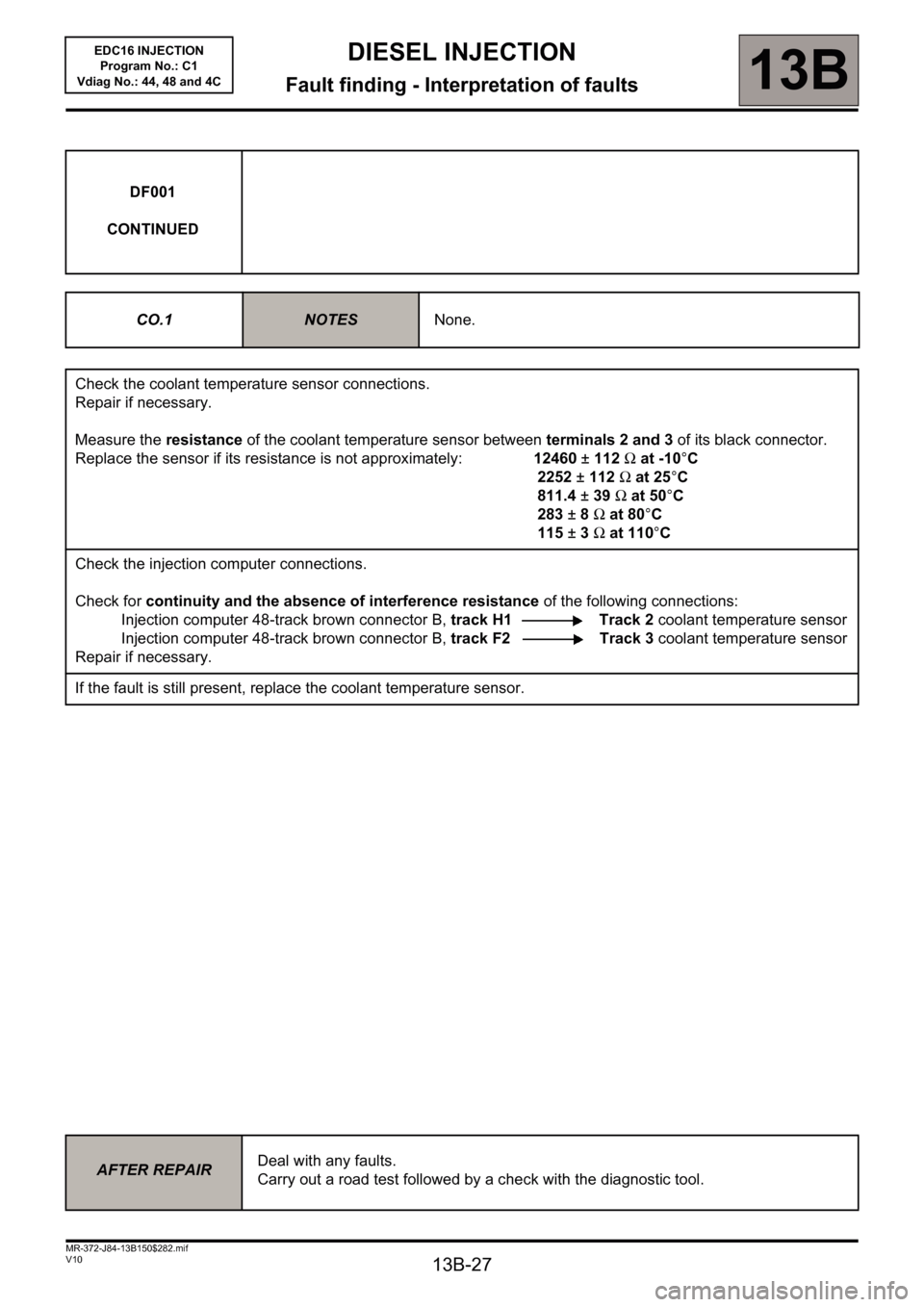
CO.1
NOTESNone.
Check the coolant temperature sensor connections.
Repair if necessary.
Measure the resistance of the coolant temperature sensor between terminals 2 and 3 of its black connector.
Replace the sensor if its resistance is not approximately: 12460±112Ω at -10°C
2252±112Ω at 25°C
811.4±39Ω at 50°C
283±8Ω at 80°C
115±3Ω at 110°C
Check the injection computer connections.
Check for continuity and the absence of interference resistance of the following connections:
Injection computer 48-track brown connector B, track H1 Track 2 coolant temperature sensor
Injection computer 48-track brown connector B, track F2 Track 3 coolant temperature sensor
Repair if necessary.
If the fault is still present, replace the coolant temperature sensor.
AFTER REPAIRDeal with any faults.
Carry out a road test followed by a check with the diagnostic tool.
Page 28 of 236
13B-28
DIESEL INJECTION
Fault finding - Interpretation of faults13B
V10 MR-372-J84-13B150$282.mif
EDC16 INJECTION
Program No.: C1
Vdiag No.: 44, 48 and 4C
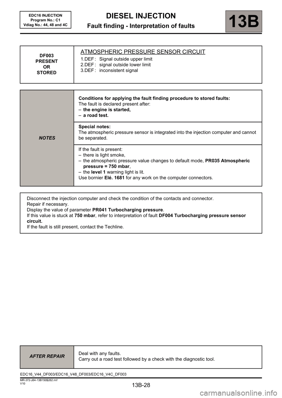
DF003
PRESENT
OR
STOREDATMOSPHERIC PRESSURE SENSOR CIRCUIT
1.DEF : Signal outside upper limit
2.DEF : signal outside lower limit
3.DEF : inconsistent signal
NOTESConditions for applying the fault finding procedure to stored faults:
The fault is declared present after:
–the engine is started,
–a road test.
Special notes:
The atmospheric pressure sensor is integrated into the injection computer and cannot
be separated.
If the fault is present:
– there is light smoke,
– the atmospheric pressure value changes to default mode, PR035 Atmospheric
pressure = 750 mbar,
–the level 1 warning light is lit.
Use bornier Elé. 1681 for any work on the computer connectors.
Disconnect the injection computer and check the condition of the contacts and connector.
Repair if necessary.
Display the value of parameter PR041 Turbocharging pressure.
If this value is stuck at 750 mbar, refer to interpretation of fault DF004 Turbocharging pressure sensor
circuit.
If the fault is still present, contact the Techline.
AFTER REPAIRDeal with any faults.
Carry out a road test followed by a check with the diagnostic tool.
EDC16_V44_DF003/EDC16_V48_DF003/EDC16_V4C_DF003
Page 29 of 236
13B-29
DIESEL INJECTION
Fault finding - Interpretation of faults13B
V10 MR-372-J84-13B150$282.mif
EDC16 INJECTION
Program No.: C1
Vdiag No.: 44, 48 and 4C
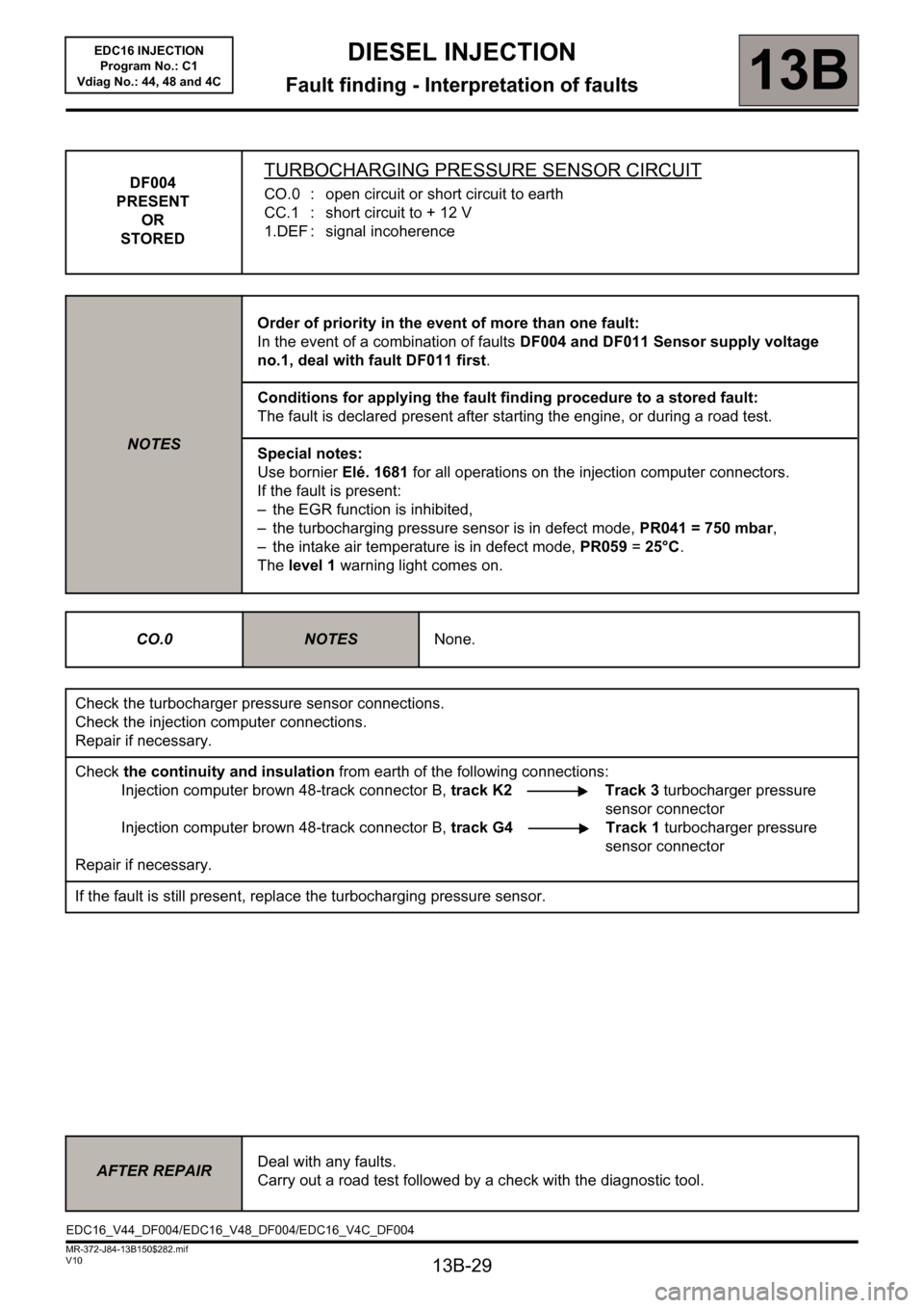
DF004
PRESENT
OR
STOREDTURBOCHARGING PRESSURE SENSOR CIRCUIT
CO.0 : open circuit or short circuit to earth
CC.1 : short circuit to + 12 V
1.DEF : signal incoherence
NOTESOrder of priority in the event of more than one fault:
In the event of a combination of faults DF004 and DF011 Sensor supply voltage
no.1, deal with fault DF011 first.
Conditions for applying the fault finding procedure to a stored fault:
The fault is declared present after starting the engine, or during a road test.
Special notes:
Use bornier Elé. 1681 for all operations on the injection computer connectors.
If the fault is present:
– the EGR function is inhibited,
– the turbocharging pressure sensor is in defect mode, PR041 = 750 mbar,
– the intake air temperature is in defect mode, PR059 = 25°C.
The level 1 warning light comes on.
CO.0
NOTESNone.
Check the turbocharger pressure sensor connections.
Check the injection computer connections.
Repair if necessary.
Check the continuity and insulation from earth of the following connections:
Injection computer brown 48-track connector B, track K2 Track 3 turbocharger pressure
sensor connector
Injection computer brown 48-track connector B, track G4 Track 1 turbocharger pressure
sensor connector
Repair if necessary.
If the fault is still present, replace the turbocharging pressure sensor.
AFTER REPAIRDeal with any faults.
Carry out a road test followed by a check with the diagnostic tool.
EDC16_V44_DF004/EDC16_V48_DF004/EDC16_V4C_DF004
Page 30 of 236
13B-30
DIESEL INJECTION
Fault finding - Interpretation of faults13B
V10 MR-372-J84-13B150$282.mif
EDC16 INJECTION
Program No.: C1
Vdiag No.: 44, 48 and 4C
DF004
CONTINUED
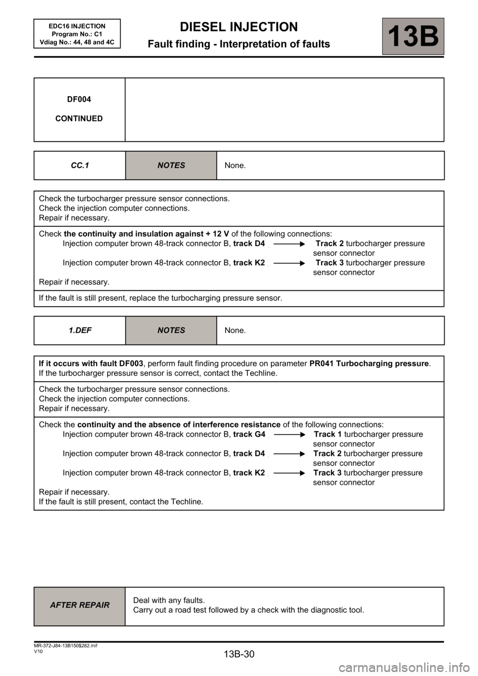
CC.1
NOTESNone.
Check the turbocharger pressure sensor connections.
Check the injection computer connections.
Repair if necessary.
Check the continuity and insulation against + 12 V of the following connections:
Injection computer brown 48-track connector B, track D4 Track 2 turbocharger pressure
sensor connector
Injection computer brown 48-track connector B, track K2 Track 3 turbocharger pressure
sensor connector
Repair if necessary.
If the fault is still present, replace the turbocharging pressure sensor.
1.DEF
NOTESNone.
If it occurs with fault DF003, perform fault finding procedure on parameter PR041 Turbocharging pressure.
If the turbocharger pressure sensor is correct, contact the Techline.
Check the turbocharger pressure sensor connections.
Check the injection computer connections.
Repair if necessary.
Check the continuity and the absence of interference resistance of the following connections:
Injection computer brown 48-track connector B, track G4 Track 1 turbocharger pressure
sensor connector
Injection computer brown 48-track connector B, track D4 Track 2 turbocharger pressure
sensor connector
Injection computer brown 48-track connector B, track K2 Track 3 turbocharger pressure
sensor connector
Repair if necessary.
If the fault is still present, contact the Techline.
AFTER REPAIRDeal with any faults.
Carry out a road test followed by a check with the diagnostic tool.
Page 31 of 236
13B-31
DIESEL INJECTION
Fault finding - Interpretation of faults13B
V10 MR-372-J84-13B150$282.mif
EDC16 INJECTION
Program No.: C1
Vdiag No.: 44, 48 and 4C
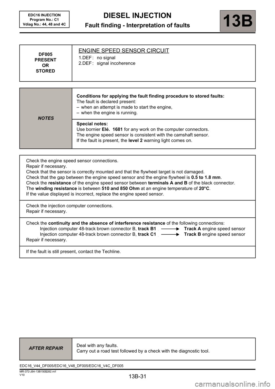
DF005
PRESENT
OR
STOREDENGINE SPEED SENSOR CIRCUIT
1.DEF : no signal
2.DEF : signal incoherence
NOTESConditions for applying the fault finding procedure to stored faults:
The fault is declared present:
– when an attempt is made to start the engine,
– when the engine is running.
Special notes:
Use bornier Elé. 1681 for any work on the computer connectors.
The engine speed sensor is consistent with the camshaft sensor.
If the fault is present, the level 2 warning light comes on.
Check the engine speed sensor connections.
Repair if necessary.
Check that the sensor is correctly mounted and that the flywheel target is not damaged.
Check that the gap between the engine speed sensor and the engine flywheel is 0.5 to 1.8 mm.
Check the resistance of the engine speed sensor between terminals A and B of the black connector.
The winding resistance is between 510 and 850 Ohm at an engine temperature of 20°C.
If the value displayed is incorrect, replace the engine speed sensor.
Check the injection computer connections.
Repair if necessary.
Check the continuity and the absence of interference resistance of the following connections:
Injection computer 48-track brown connector B, track B1 Track A engine speed sensor
Injection computer 48-track brown connector B, track C1 Track B engine speed sensor
Repair if necessary.
If the fault is still present, contact the Techline.
AFTER REPAIRDeal with any faults.
Carry out a road test followed by a check with the diagnostic tool.
EDC16_V44_DF005/EDC16_V48_DF005/EDC16_V4C_DF005
Page 32 of 236
13B-32
DIESEL INJECTION
Fault finding - Interpretation of faults13B
V10 MR-372-J84-13B150$282.mif
EDC16 INJECTION
Program No.: C1
Vdiag No.: 44, 48 and 4C
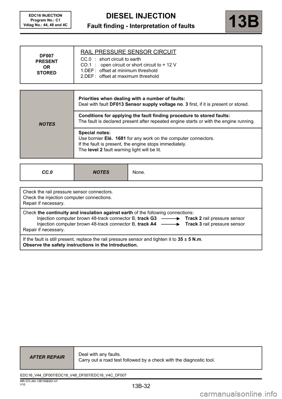
DF007
PRESENT
OR
STOREDRAIL PRESSURE SENSOR CIRCUIT
CC.0 : short circuit to earth
CO.1 : open circuit or short circuit to + 12 V
1.DEF : offset at minimum threshold
2.DEF : offset at maximum threshold
NOTESPriorities when dealing with a number of faults:
Deal with fault DF013 Sensor supply voltage no. 3 first, if it is present or stored.
Conditions for applying the fault finding procedure to stored faults:
The fault is declared present after repeated engine starts or with the engine running.
Special notes:
Use bornier Elé. 1681 for any work on the computer connectors.
If the fault is present, the engine stops immediately.
The level 2 fault warning light will be lit.
CC.0
NOTESNone.
Check the rail pressure sensor connectors.
Check the injection computer connections.
Repair if necessary.
Check the continuity and insulation against earth of the following connections:
Injection computer brown 48-track connector B, track G3 Track 2 rail pressure sensor
Injection computer brown 48-track connector B, track A4 Track 3 rail pressure sensor
Repair if necessary.
If the fault is still present, replace the rail pressure sensor and tighten it to 35 ± 5 N.m.
Observe the safety instructions in the Introduction.
AFTER REPAIRDeal with any faults.
Carry out a road test followed by a check with the diagnostic tool.
EDC16_V44_DF007/EDC16_V48_DF007/EDC16_V4C_DF007
Page 33 of 236
13B-33
DIESEL INJECTION
Fault finding - Interpretation of faults13B
V10 MR-372-J84-13B150$282.mif
EDC16 INJECTION
Program No.: C1
Vdiag No.: 44, 48 and 4C
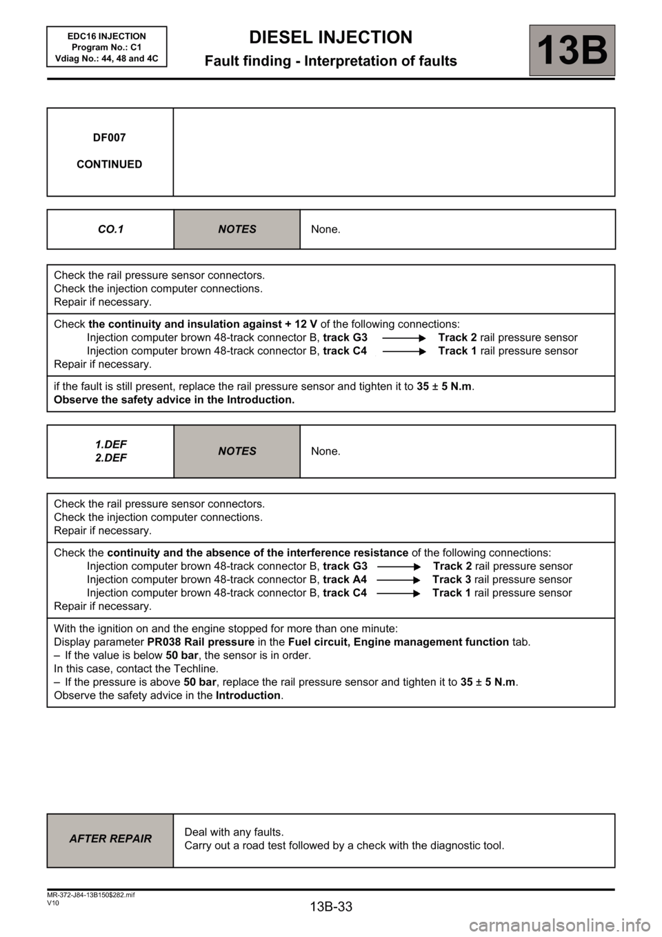
DF007
CONTINUED
CO.1
NOTESNone.
Check the rail pressure sensor connectors.
Check the injection computer connections.
Repair if necessary.
Check the continuity and insulation against + 12 V of the following connections:
Injection computer brown 48-track connector B, track G3 Track 2 rail pressure sensor
Injection computer brown 48-track connector B, track C4 Track 1 rail pressure sensor
Repair if necessary.
if the fault is still present, replace the rail pressure sensor and tighten it to 35±5N.m.
Observe the safety advice in the Introduction.
1.DEF
2.DEF
NOTESNone.
Check the rail pressure sensor connectors.
Check the injection computer connections.
Repair if necessary.
Check the continuity and the absence of the interference resistance of the following connections:
Injection computer brown 48-track connector B, track G3 Track 2 rail pressure sensor
Injection computer brown 48-track connector B, track A4 Track 3 rail pressure sensor
Injection computer brown 48-track connector B, track C4 Track 1 rail pressure sensor
Repair if necessary.
With the ignition on and the engine stopped for more than one minute:
Display parameter PR038 Rail pressure in the Fuel circuit, Engine management function tab.
– If the value is below 50 bar, the sensor is in order.
In this case, contact the Techline.
– If the pressure is above 50 bar, replace the rail pressure sensor and tighten it to 35 ± 5 N.m.
Observe the safety advice in the Introduction.
AFTER REPAIRDeal with any faults.
Carry out a road test followed by a check with the diagnostic tool.