fuel RENAULT SCENIC 2011 J95 / 3.G Engine And Peripherals EDC16 Injection Owner's Manual
[x] Cancel search | Manufacturer: RENAULT, Model Year: 2011, Model line: SCENIC, Model: RENAULT SCENIC 2011 J95 / 3.GPages: 236, PDF Size: 1.32 MB
Page 115 of 236
13B-115
DIESEL INJECTION
Fault finding - Conformity check13B
V10 MR-372-J84-13B150$423.mif
EDC16 INJECTION
Program No.: C1
Vdiag No: 44, 48 and 4C
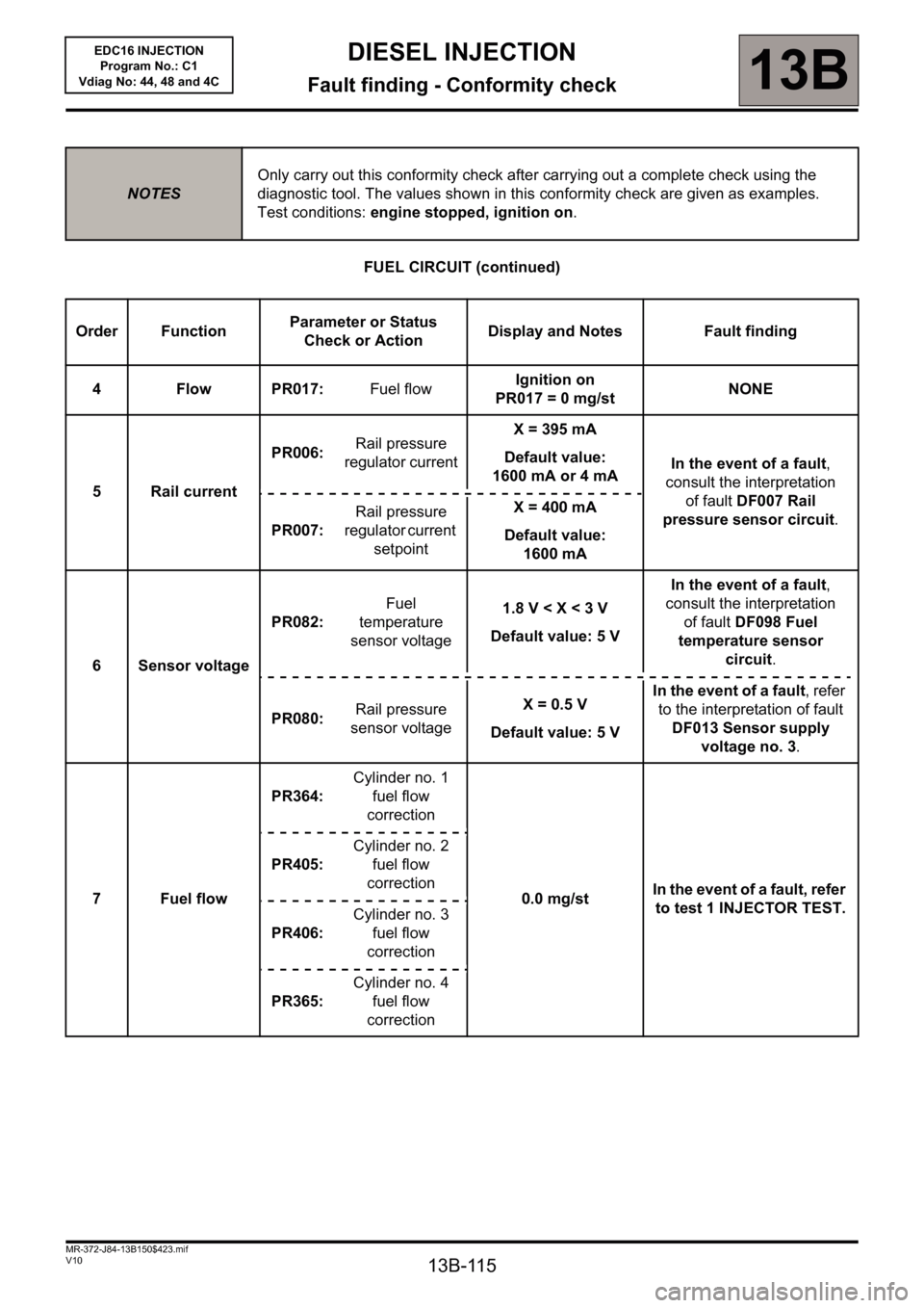
FUEL CIRCUIT (continued)
NOTESOnly carry out this conformity check after carrying out a complete check using the
diagnostic tool. The values shown in this conformity check are given as examples.
Test conditions: engine stopped, ignition on.
Order FunctionParameter or Status
Check or ActionDisplay and Notes Fault finding
4 Flow PR017: Fuel flowIgnition on
PR017= 0mg/stNONE
5 Rail currentPR006: Rail pressure
regulator currentX = 395 mA
Default value:
1600 mA or 4 mAIn the event of a fault,
consult the interpretation
of fault DF007 Rail
pressure sensor circuit.
PR007: Rail pressure
regulator current
setpointX = 400 mA
Default value:
1600 mA
6 Sensor voltagePR082: Fuel
temperature
sensor voltage1.8 V < X < 3 V
Default value: 5 VIn the event of a fault,
consult the interpretation
of fault DF098 Fuel
temperature sensor
circuit.
PR080: Rail pressure
sensor voltageX= 0.5V
Default value: 5 VIn the event of a fault, refer
to the interpretation of fault
DF013 Sensor supply
voltage no. 3.
7 Fuel flowPR364:Cylinder no. 1
fuel flow
correction
0.0 mg/stIn the event of a fault, refer
to test 1 INJECTOR TEST. PR405:Cylinder no. 2
fuel flow
correction
PR406:Cylinder no. 3
fuel flow
correction
PR365:Cylinder no. 4
fuel flow
correction
Page 133 of 236
13B-133
DIESEL INJECTION
Fault finding - Conformity check13B
V10 MR-372-J84-13B150$423.mif
EDC16 INJECTION
Program No.: C1
Vdiag No: 44, 48 and 4C
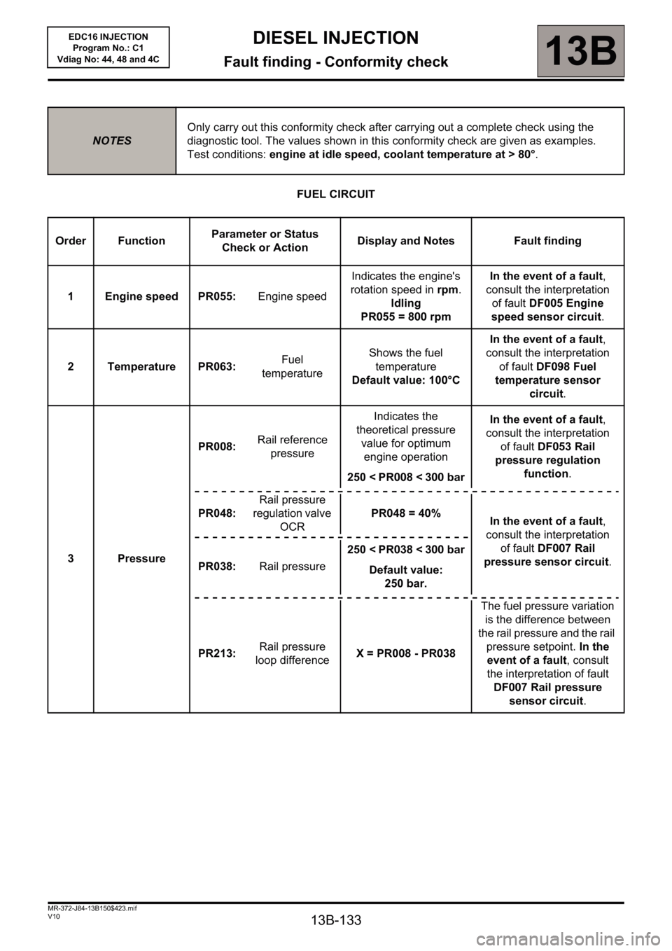
FUEL CIRCUIT
NOTESOnly carry out this conformity check after carrying out a complete check using the
diagnostic tool. The values shown in this conformity check are given as examples.
Test conditions: engine at idle speed, coolant temperature at > 80°.
Order FunctionParameter or Status
Check or ActionDisplay and Notes Fault finding
1 Engine speed PR055: Engine speedIndicates the engine's
rotation speed in rpm.
Idling
PR055 = 800 rpmIn the event of a fault,
consult the interpretation
of fault DF005 Engine
speed sensor circuit.
2 Temperature PR063: Fuel
temperatureShows the fuel
temperature
Default value: 100°CIn the event of a fault,
consult the interpretation
of fault DF098 Fuel
temperature sensor
circuit.
3PressurePR008: Rail reference
pressureIndicates the
theoretical pressure
value for optimum
engine operation
250< PR008< 300barIn the event of a fault,
consult the interpretation
of fault DF053 Rail
pressure regulation
function.
PR048:Rail pressure
regulation valve
OCRPR048 = 40%
In the event of a fault,
consult the interpretation
of fault DF007 Rail
pressure sensor circuit.
PR038: Rail pressure250< PR038< 300bar
Default value:
250 bar.
PR213: Rail pressure
loop differenceX = PR008 - PR038The fuel pressure variation
is the difference between
the rail pressure and the rail
pressure setpoint. In the
event of a fault, consult
the interpretation of fault
DF007 Rail pressure
sensor circuit.
Page 134 of 236
13B-134
DIESEL INJECTION
Fault finding - Conformity check13B
V10 MR-372-J84-13B150$423.mif
EDC16 INJECTION
Program No.: C1
Vdiag No: 44, 48 and 4C
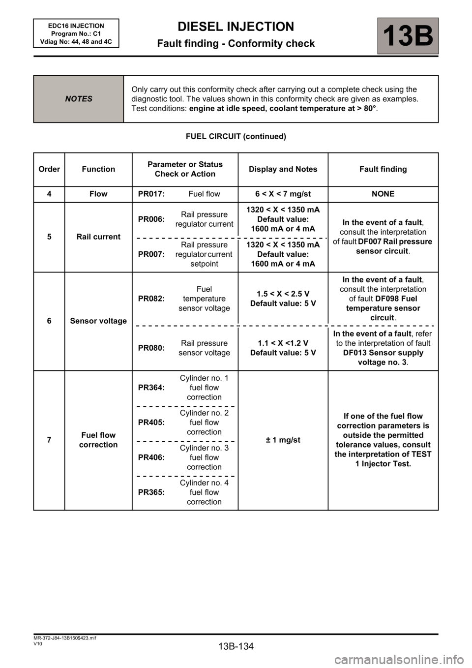
FUEL CIRCUIT (continued)
NOTESOnly carry out this conformity check after carrying out a complete check using the
diagnostic tool. The values shown in this conformity check are given as examples.
Test conditions: engine at idle speed, coolant temperature at > 80°.
Order FunctionParameter or Status
Check or ActionDisplay and Notes Fault finding
4FlowPR017: Fuel flow6 < X < 7 mg/st NONE
5 Rail currentPR006: Rail pressure
regulator current1320 < X < 1350 mA
Default value:
1600 mA or 4 mAIn the event of a fault,
consult the interpretation
of fault DF007 Rail pressure
sensor circuit.
PR007: Rail pressure
regulator current
setpoint1320 < X < 1350 mA
Default value:
1600 mA or 4 mA
6 Sensor voltagePR082: Fuel
temperature
sensor voltage1.5
consult the interpretation
of fault DF098 Fuel
temperature sensor
circuit.
PR080: Rail pressure
sensor voltage1.1 < X <1.2 V
Default value: 5 VIn the event of a fault, refer
to the interpretation of fault
DF013 Sensor supply
voltage no. 3.
7 Fuel flow
correctionPR364: Cylinder no. 1
fuel flow
correction
± 1 mg/stIf one of the fuel flow
correction parameters is
outside the permitted
tolerance values, consult
the interpretation of TEST
1 Injector Test. PR405: Cylinder no. 2
fuel flow
correction
PR406: Cylinder no. 3
fuel flow
correction
PR365: Cylinder no. 4
fuel flow
correction
Page 180 of 236
13B - 180
DIESEL INJECTION
Fault finding - Parameter summary table13B
V10 MR-372-J84-13B150$611.mif
EDC16 INJECTION
Program No.: C1
Vdiag No.: 44, 48 and 4CDIESEL INJECTION
Fault finding - Parameter summary table
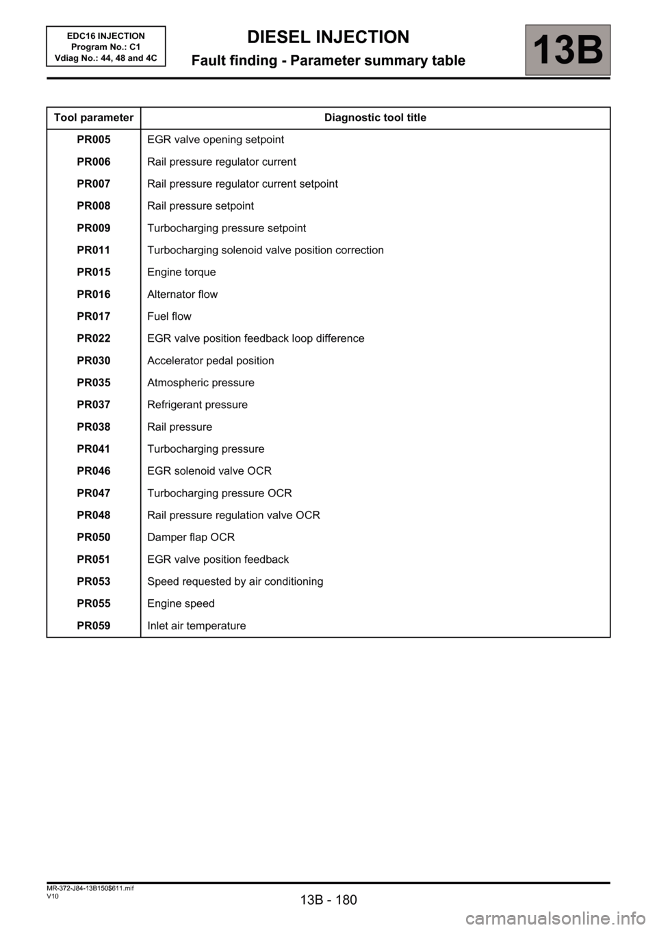
Tool parameter Diagnostic tool title
PR005EGR valve opening setpoint
PR006Rail pressure regulator current
PR007Rail pressure regulator current setpoint
PR008Rail pressure setpoint
PR009Turbocharging pressure setpoint
PR011Turbocharging solenoid valve position correction
PR015Engine torque
PR016Alternator flow
PR017Fuel flow
PR022EGR valve position feedback loop difference
PR030Accelerator pedal position
PR035Atmospheric pressure
PR037Refrigerant pressure
PR038Rail pressure
PR041Turbocharging pressure
PR046EGR solenoid valve OCR
PR047Turbocharging pressure OCR
PR048Rail pressure regulation valve OCR
PR050Damper flap OCR
PR051EGR valve position feedback
PR053Speed requested by air conditioning
PR055Engine speed
PR059Inlet air temperature
MR-372-J84-13B150$611.mif
Page 181 of 236
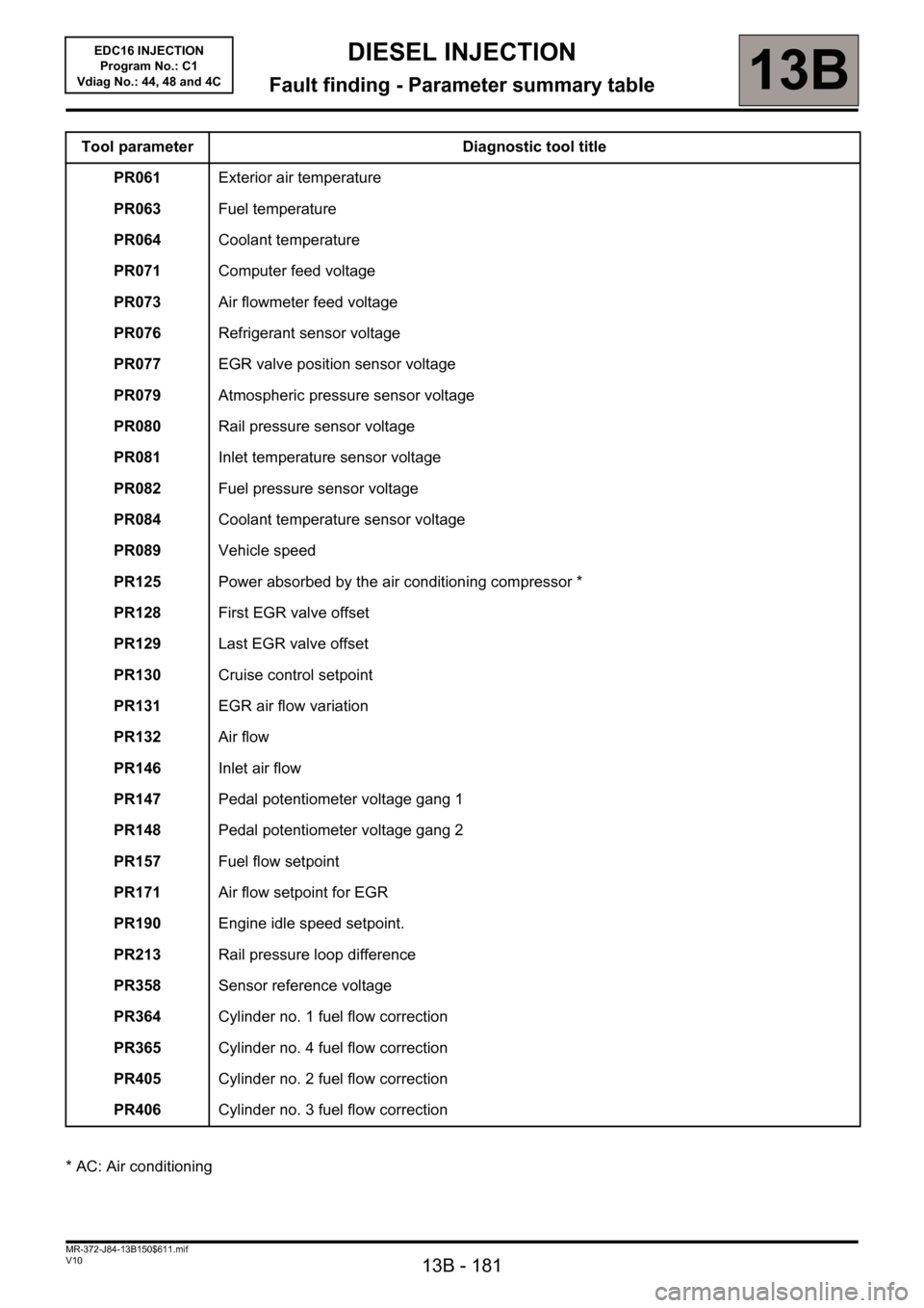
13B - 181
DIESEL INJECTION
Fault finding - Parameter summary table13B
V10 MR-372-J84-13B150$611.mif
EDC16 INJECTION
Program No.: C1
Vdiag No.: 44, 48 and 4C
Tool parameter Diagnostic tool title
PR061Exterior air temperature
PR063Fuel temperature
PR064Coolant temperature
PR071Computer feed voltage
PR073Air flowmeter feed voltage
PR076Refrigerant sensor voltage
PR077EGR valve position sensor voltage
PR079Atmospheric pressure sensor voltage
PR080Rail pressure sensor voltage
PR081Inlet temperature sensor voltage
PR082Fuel pressure sensor voltage
PR084Coolant temperature sensor voltage
PR089Vehicle speed
PR125Power absorbed by the air conditioning compressor *
PR128First EGR valve offset
PR129Last EGR valve offset
PR130Cruise control setpoint
PR131EGR air flow variation
PR132Air flow
PR146Inlet air flow
PR147Pedal potentiometer voltage gang 1
PR148Pedal potentiometer voltage gang 2
PR157Fuel flow setpoint
PR171Air flow setpoint for EGR
PR190Engine idle speed setpoint.
PR213Rail pressure loop difference
PR358Sensor reference voltage
PR364Cylinder no. 1 fuel flow correction
PR365Cylinder no. 4 fuel flow correction
PR405Cylinder no. 2 fuel flow correction
PR406Cylinder no. 3 fuel flow correction
* AC: Air conditioning
Page 184 of 236
13B - 184
DIESEL INJECTION
Fault finding - Interpretation of parameters13B
V10 MR-372-J84-13B150$658.mif
EDC16 INJECTION
Program No.: C1
Vdiag No: 44, 48 and 4C
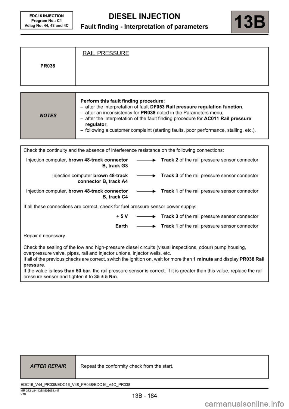
PR038
RAIL PRESSURE
NOTESPerform this fault finding procedure:
– after the interpretation of fault DF053 Rail pressure regulation function,
– after an inconsistency for PR038 noted in the Parameters menu,
– after the interpretation of the fault finding procedure for AC011 Rail pressure
regulator,
– following a customer complaint (starting faults, poor performance, stalling, etc.).
Check the continuity and the absence of interference resistance on the following connections:
Injection computer, brown 48-track connector
B, track G3Track 2 of the rail pressure sensor connector
Injection computer brown 48-track
connector B, track A4Track 3 of the rail pressure sensor connector
Injection computer, brown 48-track connector
B, track C4Track 1 of the rail pressure sensor connector
If all these connections are correct, check for fuel pressure sensor power supply:
+ 5 V Track 3 of the rail pressure sensor connector
Earth Track 1 of the rail pressure sensor connector
Repair if necessary.
Check the sealing of the low and high-pressure diesel circuits (visual inspections, odour) pump housing,
overpressure valve, pipes, rail and injector unions, injector wells, etc.
If all of the previous checks are correct, switch the ignition on, wait for more than 1 minute and display PR038 Rail
pressure.
If the value is less than 50 bar, the rail pressure sensor is correct. If it is greater than this value, replace the rail
pressure sensor and tighten it to 35 ± 5 Nm.
AFTER REPAIRRepeat the conformity check from the start.
EDC16_V44_PR038/EDC16_V48_PR038/EDC16_V4C_PR038
Page 186 of 236
13B - 186
DIESEL INJECTION
Fault finding - Interpretation of parameters13B
V10 MR-372-J84-13B150$658.mif
EDC16 INJECTION
Program No.: C1
Vdiag No: 44, 48 and 4C
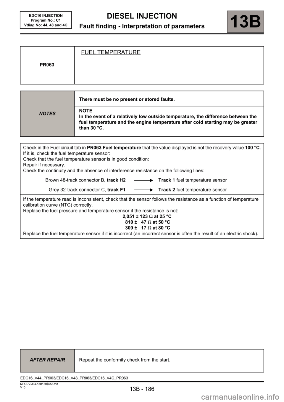
PR063
FUEL TEMPERATURE
NOTESThere must be no present or stored faults.
NOTE
In the event of a relatively low outside temperature, the difference between the
fuel temperature and the engine temperature after cold starting may be greater
than 30 °C.
Check in the Fuel circuit tab in PR063 Fuel temperature that the value displayed is not the recovery value 100 °C.
If it is, check the fuel temperature sensor:
Check that the fuel temperature sensor is in good condition:
Repair if necessary.
Check the continuity and the absence of interference resistance on the following lines:
Brown 48-track connector B, track H2 Track 1 fuel temperature sensor
Grey 32-track connector C, track F1 Track 2 fuel temperature sensor
If the temperature read is inconsistent, check that the sensor follows the resistance as a function of temperature
calibration curve (NTC) correctly.
Replace the fuel pressure and temperature sensor if the resistance is not:
2,051 ± 123Ω at 25 °C
810 ± 47Ω at 50 °C
309 ± 17Ω at 80 °C
Replace the fuel temperature sensor if it is incorrect (an incorrect sensor is often the result of an electric shock).
AFTER REPAIRRepeat the conformity check from the start.
EDC16_V44_PR063/EDC16_V48_PR063/EDC16_V4C_PR063
Page 199 of 236
13B - 199
DIESEL INJECTION
Fault finding - Interpretation of commands13B
V10 MR-372-J84-13B150$752.mif
EDC16 INJECTION
Program No.: C1
Vdiag No: 44, 48 and 4C
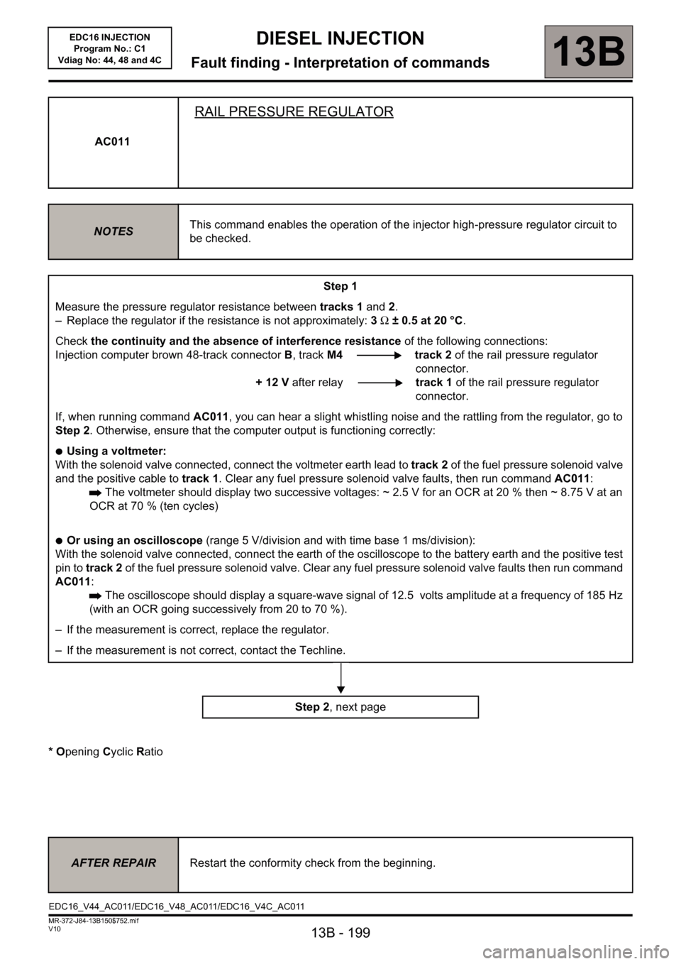
* Opening Cyclic Ratio AC011
RAIL PRESSURE REGULATOR
NOTESThis command enables the operation of the injector high-pressure regulator circuit to
be checked.
Step 1
Measure the pressure regulator resistance between tracks 1 and 2.
– Replace the regulator if the resistance is not approximately: 3Ω ± 0.5 at 20 °C.
Check the continuity and the absence of interference resistance of the following connections:
Injection computer brown 48-track connectorB, trackM4 track 2 of the rail pressure regulator
connector.
+ 12 V after relaytrack 1 of the rail pressure regulator
connector.
If, when running command AC011, you can hear a slight whistling noise and the rattling from the regulator, go to
Step 2. Otherwise, ensure that the computer output is functioning correctly:
●Using a voltmeter:
With the solenoid valve connected, connect the voltmeter earth lead to track 2 of the fuel pressure solenoid valve
and the positive cable to track 1. Clear any fuel pressure solenoid valve faults, then run command AC011:
The voltmeter should display two successive voltages: ~ 2.5 V for an OCR at 20 % then ~ 8.75 V at an
OCR at 70 % (ten cycles)
●Or using an oscilloscope (range 5 V/division and with time base 1 ms/division):
With the solenoid valve connected, connect the earth of the oscilloscope to the battery earth and the positive test
pin to track 2 of the fuel pressure solenoid valve. Clear any fuel pressure solenoid valve faults then run command
AC011:
The oscilloscope should display a square-wave signal of 12.5 volts amplitude at a frequency of 185 Hz
(with an OCR going successively from 20 to 70 %).
– If the measurement is correct, replace the regulator.
– If the measurement is not correct, contact the Techline.
Step 2, next page
AFTER REPAIRRestart the conformity check from the beginning.
EDC16_V44_AC011/EDC16_V48_AC011/EDC16_V4C_AC011
Page 205 of 236
13B-205
MR-372-J84-13B150$846.mif
V10
DIESEL INJECTION
Fault finding - Fault finding chart13B
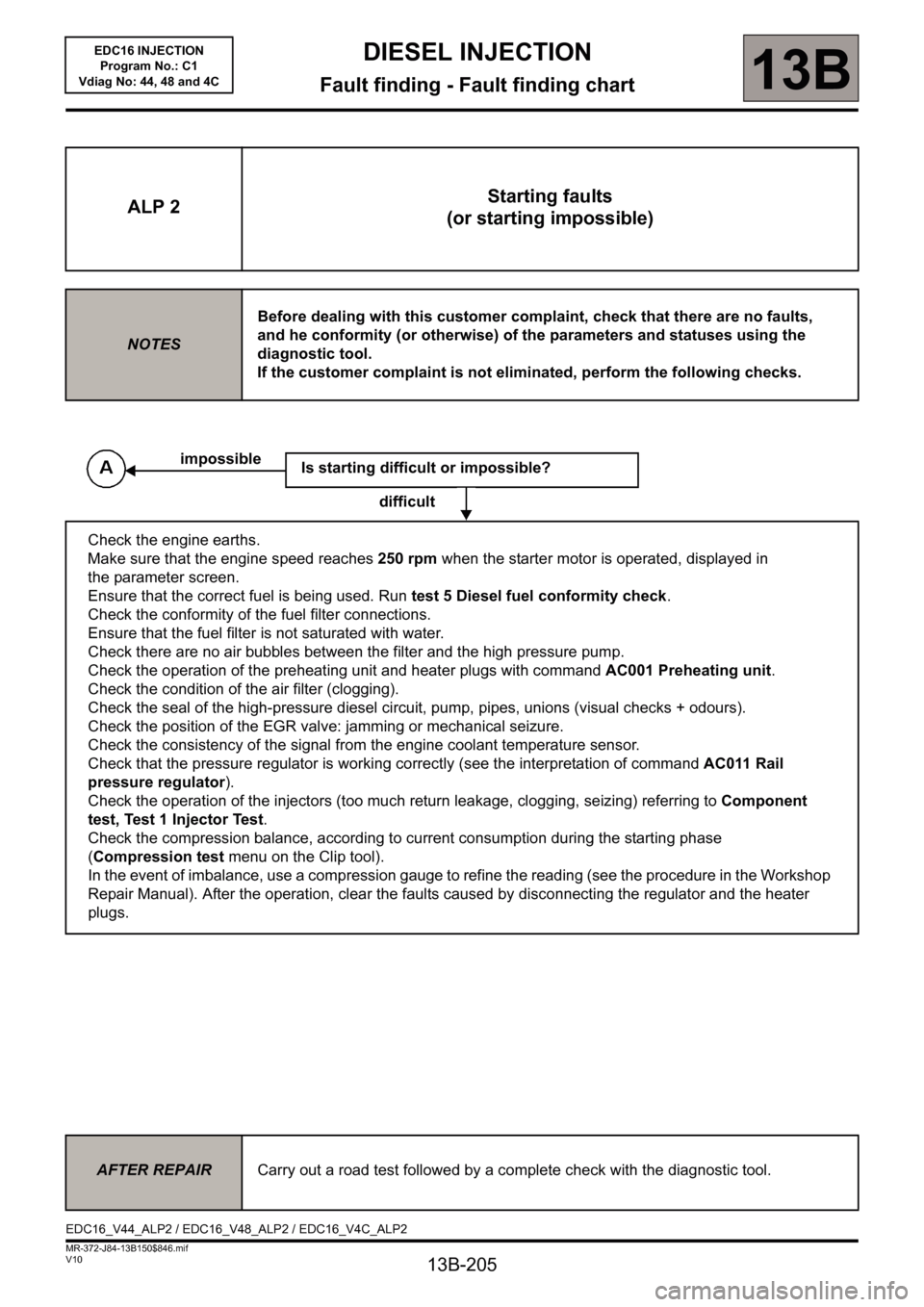
ALP 2Starting faults
(or starting impossible)
NOTESBefore dealing with this customer complaint, check that there are no faults,
and he conformity (or otherwise) of the parameters and statuses using the
diagnostic tool.
If the customer complaint is not eliminated, perform the following checks.
Is starting difficult or impossible?
difficult
Check the engine earths.
Make sure that the engine speed reaches 250 rpm when the starter motor is operated, displayed in
the parameter screen.
Ensure that the correct fuel is being used. Run test 5 Diesel fuel conformity check.
Check the conformity of the fuel filter connections.
Ensure that the fuel filter is not saturated with water.
Check there are no air bubbles between the filter and the high pressure pump.
Check the operation of the preheating unit and heater plugs with command AC001 Preheating unit.
Check the condition of the air filter (clogging).
Check the seal of the high-pressure diesel circuit, pump, pipes, unions (visual checks + odours).
Check the position of the EGR valve: jamming or mechanical seizure.
Check the consistency of the signal from the engine coolant temperature sensor.
Check that the pressure regulator is working correctly (see the interpretation of command AC011 Rail
pressure regulator).
Check the operation of the injectors (too much return leakage, clogging, seizing) referring to Component
test, Test 1 Injector Test.
Check the compression balance, according to current consumption during the starting phase
(Compression test menu on the Clip tool).
In the event of imbalance, use a compression gauge to refine the reading (see the procedure in the Workshop
Repair Manual). After the operation, clear the faults caused by disconnecting the regulator and the heater
plugs.
impossible
AFTER REPAIRCarry out a road test followed by a complete check with the diagnostic tool.
EDC16_V44_ALP2 / EDC16_V48_ALP2 / EDC16_V4C_ALP2
EDC16 INJECTION
Program No.: C1
Vdiag No: 44, 48 and 4C
Page 206 of 236
13B-206
MR-372-J84-13B150$846.mif
V10
DIESEL INJECTION
Fault finding - Fault finding chart13B
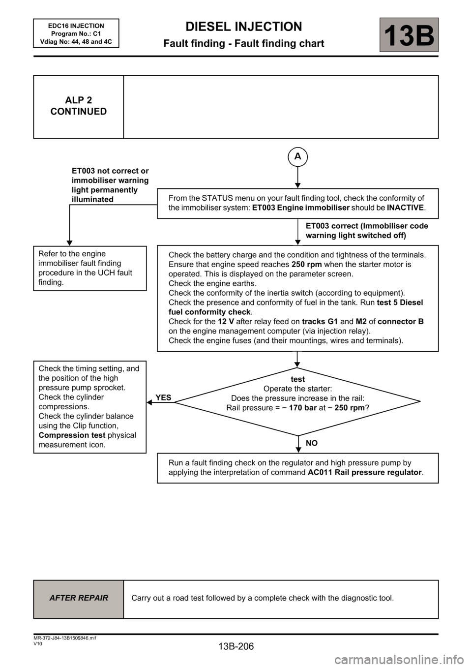
ALP 2
CONTINUED
Refer to the engine
immobiliser fault finding
procedure in the UCH fault
finding.
Check the timing setting, and
the position of the high
pressure pump sprocket.
Check the cylinder
compressions.
Check the cylinder balance
using the Clip function,
Compression test physical
measurement icon.
ET003 not correct or
immobiliser warning
light permanently
illuminated
YESFrom the STATUS menu on your fault finding tool, check the conformity of
the immobiliser system: ET003 Engine immobiliser should be INACTIVE.
ET003 correct (Immobiliser code
warning light switched off)
Check the battery charge and the condition and tightness of the terminals.
Ensure that engine speed reaches 250 rpm when the starter motor is
operated. This is displayed on the parameter screen.
Check the engine earths.
Check the conformity of the inertia switch (according to equipment).
Check the presence and conformity of fuel in the tank. Run test 5 Diesel
fuel conformity check.
Check for the 12 V after relay feed on tracks G1 and M2 of connector B
on the engine management computer (via injection relay).
Check the engine fuses (and their mountings, wires and terminals).
test
Operate the starter:
Does the pressure increase in the rail:
Rail pressure = ~ 170 bar at ~ 250 rpm?
NO
Run a fault finding check on the regulator and high pressure pump by
applying the interpretation of command AC011 Rail pressure regulator.
AFTER REPAIRCarry out a road test followed by a complete check with the diagnostic tool.
EDC16 INJECTION
Program No.: C1
Vdiag No: 44, 48 and 4C