ignition RENAULT SCENIC 2011 J95 / 3.G Engine And Peripherals EDC16 Injection Repair Manual
[x] Cancel search | Manufacturer: RENAULT, Model Year: 2011, Model line: SCENIC, Model: RENAULT SCENIC 2011 J95 / 3.GPages: 236, PDF Size: 1.32 MB
Page 151 of 236
DIESEL INJECTION
Fault finding - Interpretation of statuses13B
13B-151V10 MR-372-J84-13B150$564.mif
EDC16 INJECTION
Program No.: C1
Vdiag No.: 44, 48 and 4C
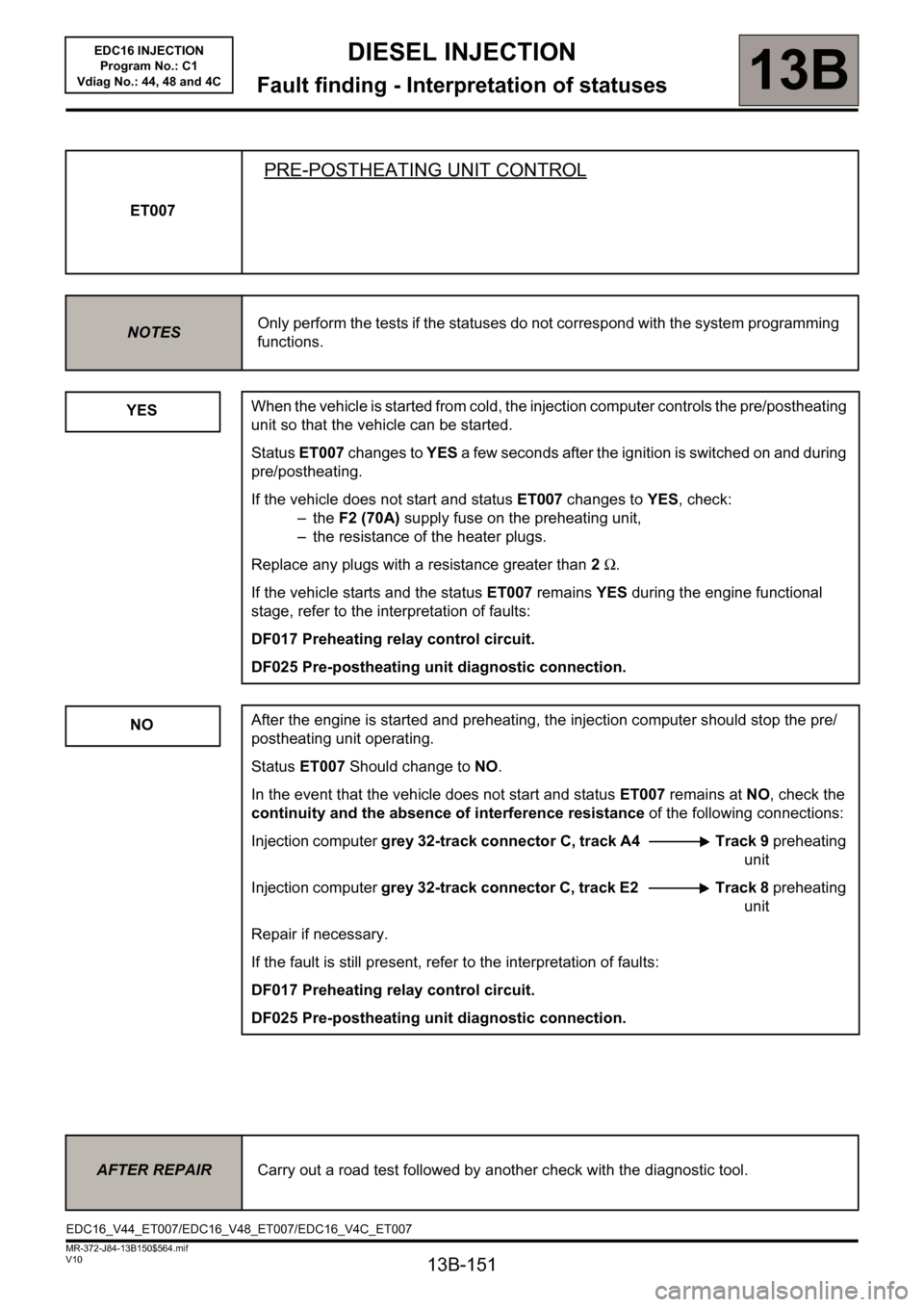
ET007
PRE-POSTHEATING UNIT CONTROL
NOTESOnly perform the tests if the statuses do not correspond with the system programming
functions.
YES
NO
When the vehicle is started from cold, the injection computer controls the pre/postheating
unit so that the vehicle can be started.
Status ET007 changes to YES a few seconds after the ignition is switched on and during
pre/postheating.
If the vehicle does not start and status ET007 changes to YES, check:
–the F2 (70A) supply fuse on the preheating unit,
– the resistance of the heater plugs.
Replace any plugs with a resistance greater than 2 Ω.
If the vehicle starts and the status ET007 remains YES during the engine functional
stage, refer to the interpretation of faults:
DF017 Preheating relay control circuit.
DF025 Pre-postheating unit diagnostic connection.
After the engine is started and preheating, the injection computer should stop the pre/
postheating unit operating.
Status ET007 Should change to NO.
In the event that the vehicle does not start and status ET007 remains at NO, check the
continuity and the absence of interference resistance of the following connections:
Injection computer grey 32-track connector C, track A4 Track 9 preheating
unit
Injection computer grey 32-track connector C, track E2 Track 8 preheating
unit
Repair if necessary.
If the fault is still present, refer to the interpretation of faults:
DF017 Preheating relay control circuit.
DF025 Pre-postheating unit diagnostic connection.
AFTER REPAIRCarry out a road test followed by another check with the diagnostic tool.
EDC16_V44_ET007/EDC16_V48_ET007/EDC16_V4C_ET007
Page 156 of 236

13B-156
DIESEL INJECTION
Fault finding - Interpretation of statuses13B
V10 MR-372-J84-13B150$564.mif
EDC16 INJECTION
Program No.: C1
Vdiag No.: 44, 48 and 4C
ET038
ENGINE
STOPPEDStatus ET038 is stopped if the engine ignition is on but there has been no starter
operation.
STALLEDStatus ET038 is stalled when the engine has stalled. The vehicle is still under + after
ignition feed.
RUNNINGStatus ET038 is running if the engine has started.
STARTINGStatus ET038 is starter if the engine is in starting phase.
AFTER REPAIRCarry out a road test followed by another check with the diagnostic tool.
EDC16_V44_ET038/EDC16_V48_ET038/EDC16_V4C_ET038
Page 159 of 236
13B-159
DIESEL INJECTION
Fault finding - Interpretation of statuses13B
V10 MR-372-J84-13B150$564.mif
EDC16 INJECTION
Program No.: C1
Vdiag No.: 44, 48 and 4C
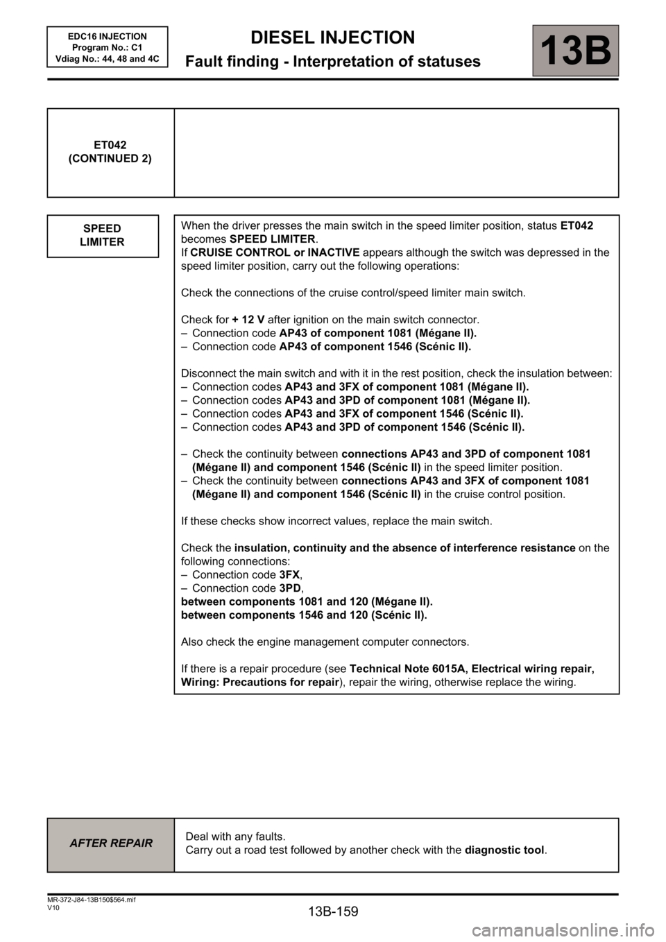
ET042
(CONTINUED 2)
SPEED
LIMITER
When the driver presses the main switch in the speed limiter position, status ET042
becomes SPEED LIMITER.
If CRUISE CONTROL or INACTIVE appears although the switch was depressed in the
speed limiter position, carry out the following operations:
Check the connections of the cruise control/speed limiter main switch.
Check for + 12 V after ignition on the main switch connector.
– Connection code AP43 of component 1081 (Mégane II).
– Connection code AP43 of component 1546 (Scénic II).
Disconnect the main switch and with it in the rest position, check the insulation between:
– Connection codes AP43 and 3FX of component 1081 (Mégane II).
– Connection codes AP43 and 3PD of component 1081 (Mégane II).
– Connection codes AP43 and 3FX of component 1546 (Scénic II).
– Connection codes AP43 and 3PD of component 1546 (Scénic II).
– Check the continuity between connections AP43 and 3PD of component 1081
(Mégane II) and component 1546 (Scénic II) in the speed limiter position.
– Check the continuity between connections AP43 and 3FX of component 1081
(Mégane II) and component 1546 (Scénic II) in the cruise control position.
If these checks show incorrect values, replace the main switch.
Check the insulation, continuity and the absence of interference resistance on the
following connections:
– Connection code 3FX,
– Connection code 3PD,
between components 1081 and 120 (Mégane II).
between components 1546 and 120 (Scénic II).
Also check the engine management computer connectors.
If there is a repair procedure (see Technical Note 6015A, Electrical wiring repair,
Wiring: Precautions for repair), repair the wiring, otherwise replace the wiring.
AFTER REPAIRDeal with any faults.
Carry out a road test followed by another check with the diagnostic tool.
Page 160 of 236
13B-160
DIESEL INJECTION
Fault finding - Interpretation of statuses13B
V10 MR-372-J84-13B150$564.mif
EDC16 INJECTION
Program No.: C1
Vdiag No.: 44, 48 and 4C
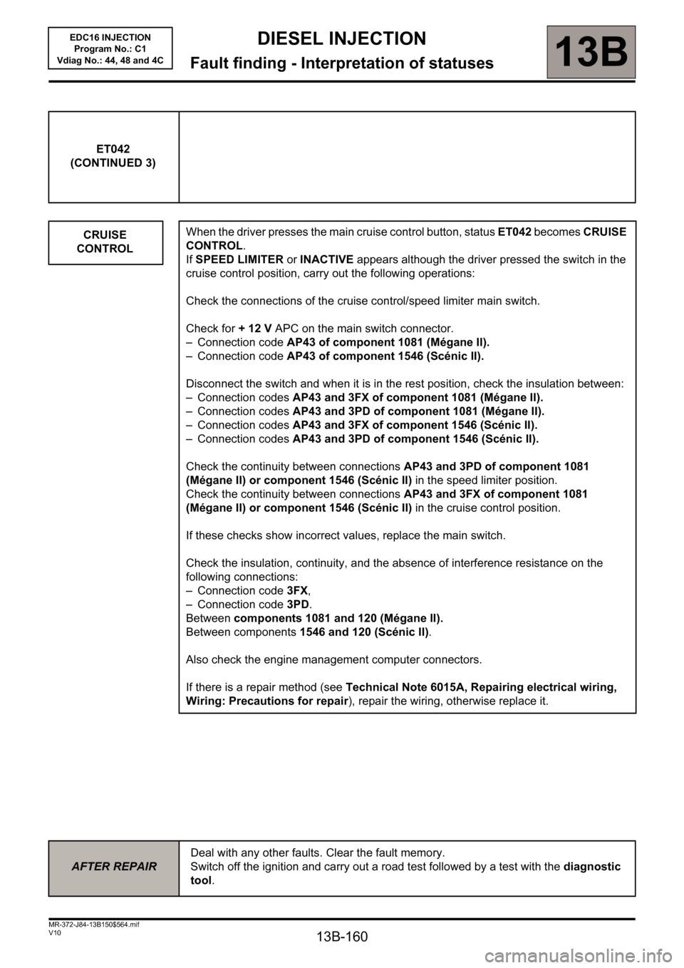
ET042
(CONTINUED 3)
CRUISE
CONTROL
When the driver presses the main cruise control button, status ET042 becomes CRUISE
CONTROL.
If SPEED LIMITER or INACTIVE appears although the driver pressed the switch in the
cruise control position, carry out the following operations:
Check the connections of the cruise control/speed limiter main switch.
Check for + 12 V APC on the main switch connector.
– Connection code AP43 of component 1081 (Mégane II).
– Connection code AP43 of component 1546 (Scénic II).
Disconnect the switch and when it is in the rest position, check the insulation between:
– Connection codes AP43 and 3FX of component 1081 (Mégane II).
– Connection codes AP43 and 3PD of component 1081 (Mégane II).
– Connection codes AP43 and 3FX of component 1546 (Scénic II).
– Connection codes AP43 and 3PD of component 1546 (Scénic II).
Check the continuity between connections AP43 and 3PD of component 1081
(Mégane II) or component 1546 (Scénic II) in the speed limiter position.
Check the continuity between connections AP43 and 3FX of component 1081
(Mégane II) or component 1546 (Scénic II) in the cruise control position.
If these checks show incorrect values, replace the main switch.
Check the insulation, continuity, and the absence of interference resistance on the
following connections:
– Connection code 3FX,
– Connection code3PD.
Between components 1081 and 120 (Mégane II).
Between components 1546 and 120 (Scénic II).
Also check the engine management computer connectors.
If there is a repair method (see Technical Note 6015A, Repairing electrical wiring,
Wiring: Precautions for repair), repair the wiring, otherwise replace it.
AFTER REPAIRDeal with any other faults. Clear the fault memory.
Switch off the ignition and carry out a road test followed by a test with the diagnostic
tool.
Page 162 of 236

DIESEL INJECTION
Fault finding - Interpretation of statuses13B
13B-162V10 MR-372-J84-13B150$564.mif
EDC16 INJECTION
Program No.: C1
Vdiag No.: 44, 48 and 4C
ET077
IMPACT DETECTED
NOTESOnly perform the tests if the statuses do not correspond with the system programming
functions.
YES
NO
If the vehicle has been involved in an accident, the injection computer receives the
impact signal via the multiplex network and may switch off the ignition. Status ET077 is
at YES.
Switch off the ignition for ten seconds, then switch it back on to enable the engine to start.
Carry out a multiplex network test and deal with any faults.
Clear the injection computer faults, even if no fault is present.
In normal operating conditions, status ET077 is NO when the computer has received no
impact signal.
AFTER REPAIRCarry out a road test followed by another check with the diagnostic tool.
EDC16_V44_ET077/EDC16_V48_ET077/EDC16_V4C_ET077
Page 166 of 236

DIESEL INJECTION
Fault finding - Interpretation of statuses13B
13B-166V10 MR-372-J84-13B150$564.mif
EDC16 INJECTION
Program No.: C1
Vdiag No.: 44, 48 and 4C
ET238
SYNCHRONISATION
NOTESOnly perform the tests if the statuses do not correspond with the system programming
functions.
WARNING
Synchronisation is carried out during the engine starting phase. This is established between the camshaft
position sensor and the TDC sensor.
Once this synchronisation has been carried out, it enables the computer to identify cylinder no.1 and to
ascertain the precise position of the cylinder's top dead centre.
INACTIVE
COMPLETED
When the engine is stopped but the ignition switched on, cylinder no. 1 is no longer
indicated.
Status ET238 is INACTIVE, no synchronisation between the crankshaft and the
camshaft is performed.
Synchronisation is carried out during the engine starting phase.
Cylinder No. 1 is indicated and synchronisation will be performed once the engine is
started.
Status ET238 is "COMPLETED".
If after several attempts to start the engine status ET238 remains INACTIVE, refer to the
interpretation of the following faults:
–DF005 Engine speed sensor circuit
–DF097 Camshaft sensor circuit
If the engine still does not start, (see Customer complaints, ALP2 Starting faults).
AFTER REPAIRCarry out a road test followed by another check with the diagnostic tool.
EDC16_V44_ET238/EDC16_V48_ET238/EDC16_V4C_ET238
Page 168 of 236
13B-168
DIESEL INJECTION
Fault finding - Interpretation of statuses13B
V10 MR-372-J84-13B150$564.mif
EDC16 INJECTION
Program No.: C1
Vdiag No.: 44, 48 and 4C
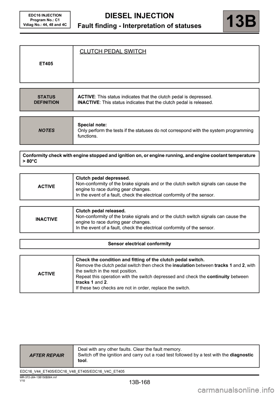
ET405
CLUTCH PEDAL SWITCH
STATUS
DEFINITIONACTIVE: This status indicates that the clutch pedal is depressed.
INACTIVE: This status indicates that the clutch pedal is released.
NOTESSpecial note:
Only perform the tests if the statuses do not correspond with the system programming
functions.
Conformity check with engine stopped and ignition on, or engine running, and engine coolant temperature
> 80°C
ACTIVEClutch pedal depressed.
Non-conformity of the brake signals and or the clutch switch signals can cause the
engine to race during gear changes.
In the event of a fault, check the electrical conformity of the sensor.
INACTIVEClutch pedal released.
Non-conformity of the brake signals and or the clutch switch signals can cause the
engine to race during gear changes.
In the event of a fault, check the electrical conformity of the sensor.
Sensor electrical conformity
ACTIVECheck the condition and fitting of the clutch pedal switch.
Remove the clutch pedal switch then check the insulation between tracks 1 and 2, with
the switch in the rest position.
Repeat this operation with the switch depressed and check the continuity between
tracks 1 and 2.
If these two checks are not in order, replace the switch.
AFTER REPAIRDeal with any other faults. Clear the fault memory.
Switch off the ignition and carry out a road test followed by a test with the diagnostic
tool.
ET405
CLUTCH PEDAL SWITCH
STATUS
DEFINITIONACTIVE: This status indicates that the clutch pedal is depressed.
INACTIVE: This status indicates that the clutch pedal is released.
NOTESSpecial note:
Only perform the tests if the statuses do not correspond with the system programming
functions.
Conformity check with engine stopped and ignition on, or engine running, and engine coolant temperature
> 80°C
ACTIVEClutch pedal depressed.
Non-conformity of the brake signals and or the clutch switch signals can cause the
engine to race during gear changes.
In the event of a fault, check the electrical conformity of the sensor.
INACTIVEClutch pedal released.
Non-conformity of the brake signals and or the clutch switch signals can cause the
engine to race during gear changes.
In the event of a fault, check the electrical conformity of the sensor.
Sensor electrical conformity
EDC16_V44_ET405/EDC16_V48_ET405/EDC16_V4C_ET405
Page 169 of 236
13B-169
DIESEL INJECTION
Fault finding - Interpretation of statuses13B
V10 MR-372-J84-13B150$564.mif
EDC16 INJECTION
Program No.: C1
Vdiag No.: 44, 48 and 4C
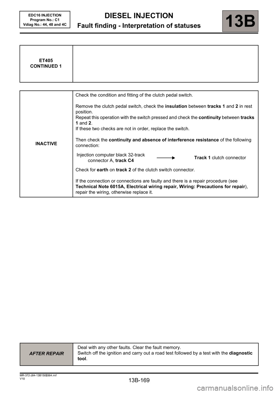
ET405
CONTINUED 1
INACTIVECheck the condition and fitting of the clutch pedal switch.
Remove the clutch pedal switch, check the insulation between tracks 1 and 2 in rest
position.
Repeat this operation with the switch pressed and check the continuity between tracks
1 and 2.
If these two checks are not in order, replace the switch.
Then check the continuity and absence of interference resistance of the following
connection:
Injection computer black 32-track
connector A, track C4Track 1 clutch connector
Check for earth on track 2 of the clutch switch connector.
If the connection or connections are faulty and there is a repair procedure (see
Technical Note 6015A, Electrical wiring repair, Wiring: Precautions for repair),
repair the wiring, otherwise replace it.
AFTER REPAIRDeal with any other faults. Clear the fault memory.
Switch off the ignition and carry out a road test followed by a test with the diagnostic
tool.
Page 170 of 236
13B-170
DIESEL INJECTION
Fault finding - Interpretation of statuses13B
V10 MR-372-J84-13B150$564.mif
EDC16 INJECTION
Program No.: C1
Vdiag No.: 44, 48 and 4C
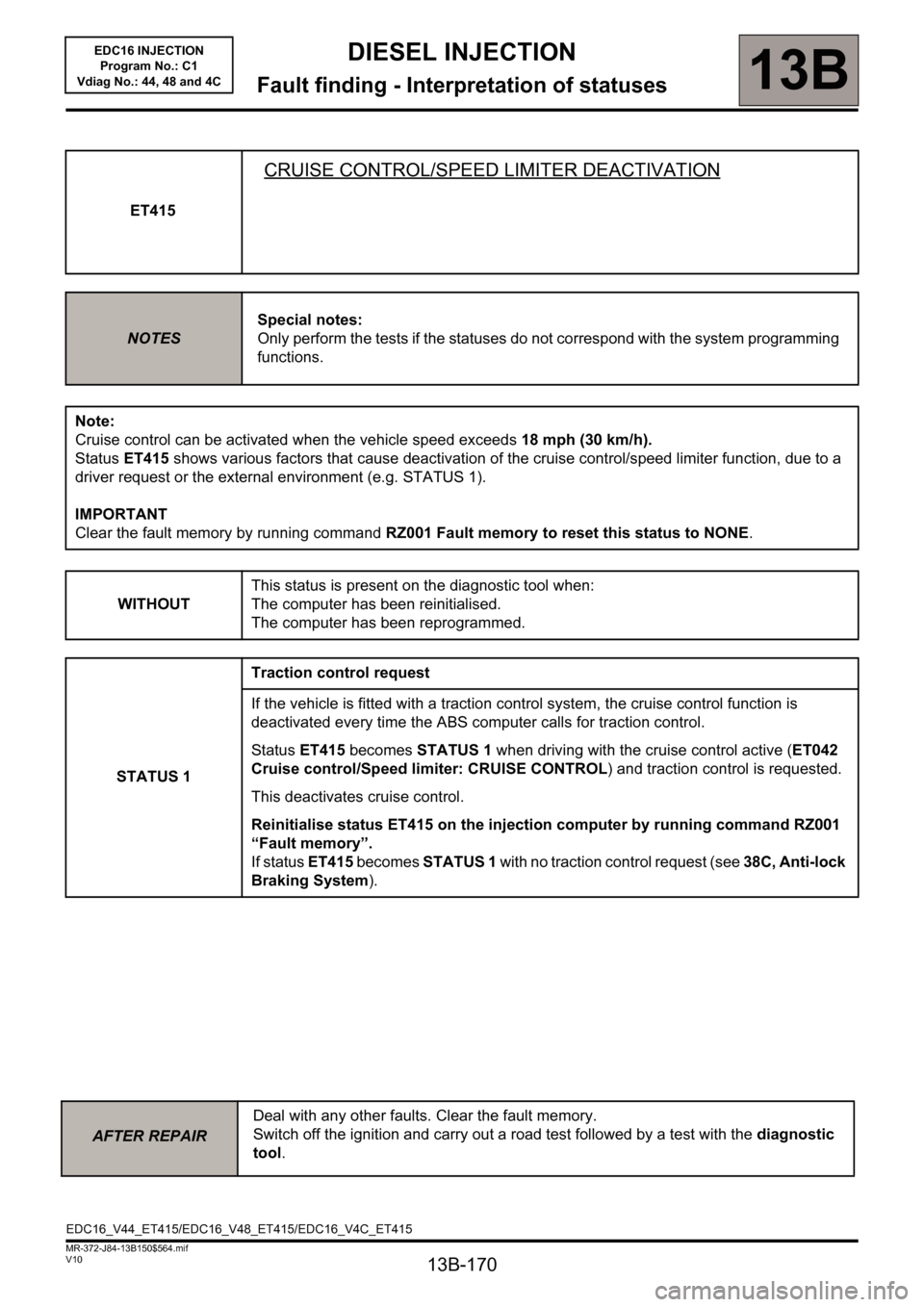
ET415
CRUISE CONTROL/SPEED LIMITER DEACTIVATION
NOTESSpecial notes:
Only perform the tests if the statuses do not correspond with the system programming
functions.
Note:
Cruise control can be activated when the vehicle speed exceeds 18 mph (30 km/h).
Status ET415 shows various factors that cause deactivation of the cruise control/speed limiter function, due to a
driver request or the external environment (e.g. STATUS 1).
IMPORTANT
Clear the fault memory by running command RZ001 Fault memory to reset this status to NONE.
WITHOUTThis status is present on the diagnostic tool when:
The computer has been reinitialised.
The computer has been reprogrammed.
STATUS 1Traction control request
If the vehicle is fitted with a traction control system, the cruise control function is
deactivated every time the ABS computer calls for traction control.
Status ET415 becomes STATUS 1 when driving with the cruise control active (ET042
Cruise control/Speed limiter: CRUISE CONTROL) and traction control is requested.
This deactivates cruise control.
Reinitialise status ET415 on the injection computer by running command RZ001
“Fault memory”.
If status ET415 becomes STATUS 1 with no traction control request (see 38C, Anti-lock
Braking System).
AFTER REPAIRDeal with any other faults. Clear the fault memory.
Switch off the ignition and carry out a road test followed by a test with the diagnostic
tool.
EDC16_V44_ET415/EDC16_V48_ET415/EDC16_V4C_ET415
Page 171 of 236
13B-171
DIESEL INJECTION
Fault finding - Interpretation of statuses13B
V10 MR-372-J84-13B150$564.mif
EDC16 INJECTION
Program No.: C1
Vdiag No.: 44, 48 and 4C
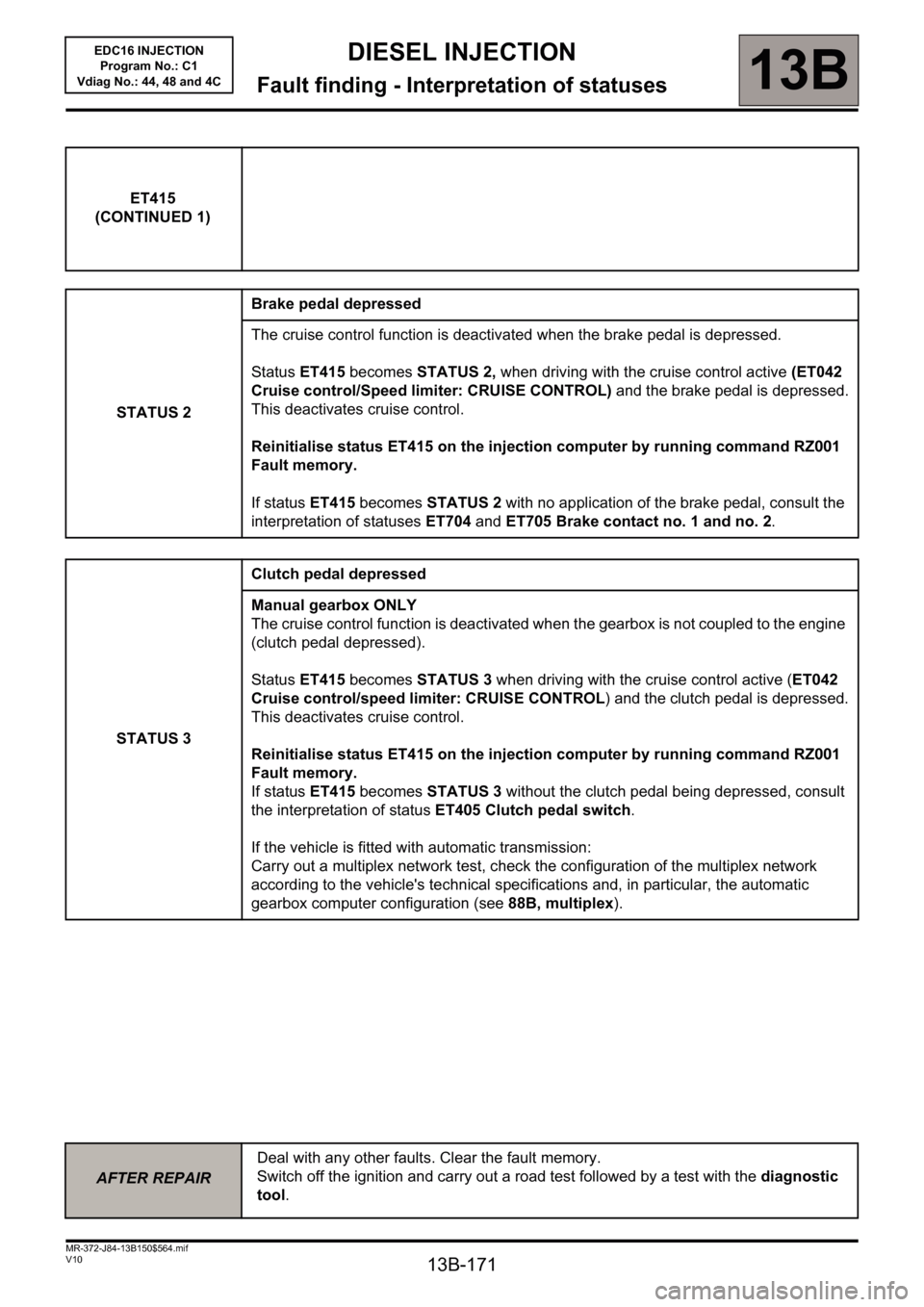
ET415
(CONTINUED 1)
STATUS 2Brake pedal depressed
The cruise control function is deactivated when the brake pedal is depressed.
Status ET415 becomes STATUS 2, when driving with the cruise control active (ET042
Cruise control/Speed limiter: CRUISE CONTROL) and the brake pedal is depressed.
This deactivates cruise control.
Reinitialise status ET415 on the injection computer by running command RZ001
Fault memory.
If status ET415 becomes STATUS 2 with no application of the brake pedal, consult the
interpretation of statuses ET704 and ET705 Brake contact no. 1 and no. 2.
STATUS 3Clutch pedal depressed
Manual gearbox ONLY
The cruise control function is deactivated when the gearbox is not coupled to the engine
(clutch pedal depressed).
Status ET415 becomes STATUS 3 when driving with the cruise control active (ET042
Cruise control/speed limiter: CRUISE CONTROL) and the clutch pedal is depressed.
This deactivates cruise control.
Reinitialise status ET415 on the injection computer by running command RZ001
Fault memory.
If status ET415 becomes STATUS 3 without the clutch pedal being depressed, consult
the interpretation of status ET405 Clutch pedal switch.
If the vehicle is fitted with automatic transmission:
Carry out a multiplex network test, check the configuration of the multiplex network
according to the vehicle's technical specifications and, in particular, the automatic
gearbox computer configuration (see 88B, multiplex).
AFTER REPAIRDeal with any other faults. Clear the fault memory.
Switch off the ignition and carry out a road test followed by a test with the diagnostic
tool.