air condition RENAULT SCENIC 2011 J95 / 3.G Engine And Peripherals EDC16 Workshop Manual
[x] Cancel search | Manufacturer: RENAULT, Model Year: 2011, Model line: SCENIC, Model: RENAULT SCENIC 2011 J95 / 3.GPages: 365, PDF Size: 2.11 MB
Page 335 of 365
13B-335
MR-372-J84-13B200$828.mif
V13
DIESEL INJECTION
Fault finding – Fault Finding Chart
EDC16
Program No.: C1
Vdiag no.: 18, 1C, 20,
50, 58, 5C
13B
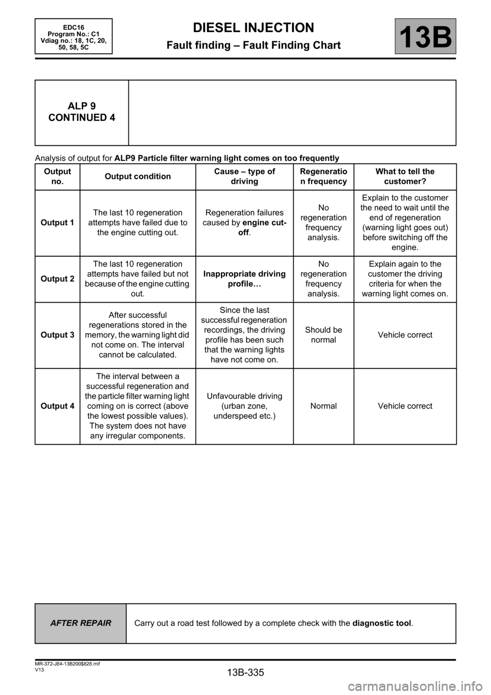
Analysis of output for ALP9 Particle filter warning light comes on too frequently
ALP 9
CONTINUED 4
Output
no. Output conditionCause – type of
drivingRegeneratio
n frequencyWhat to tell the
customer?
Output 1The last 10 regeneration
attempts have failed due to
the engine cutting out.Regeneration failures
caused by engine cut-
off.No
regeneration
frequency
analysis.Explain to the customer
the need to wait until the
end of regeneration
(warning light goes out)
before switching off the
engine.
Output 2The last 10 regeneration
attempts have failed but not
because of the engine cutting
out.Inappropriate driving
profile…No
regeneration
frequency
analysis.Explain again to the
customer the driving
criteria for when the
warning light comes on.
Output 3After successful
regenerations stored in the
memory, the warning light did
not come on. The interval
cannot be calculated.Since the last
successful regeneration
recordings, the driving
profile has been such
that the warning lights
have not come on.Should be
normalVehicle correct
Output 4The interval between a
successful regeneration and
the particle filter warning light
coming on is correct (above
the lowest possible values).
The system does not have
any irregular components.Unfavourable driving
(urban zone,
underspeed etc.)Normal Vehicle correct
AFTER REPAIRCarry out a road test followed by a complete check with the diagnostic tool.
Page 341 of 365
13B-341
MR-372-J84-13B200$900.mif
V13
EDC16
Program No.: C1
Vdiag no.: 18, 1C, 20,
50, 58, 5CDIESEL INJECTION
Fault finding – Tests13B
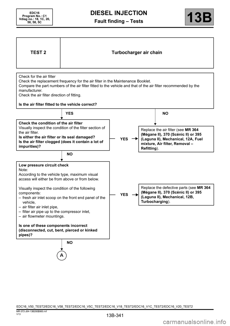
TEST 2 Turbocharger air chain
Check for the air filter
Check the replacement frequency for the air filter in the Maintenance Booklet.
Compare the part numbers of the air filter fitted to the vehicle and that of the air filter recommended by the
manufacturer.
Check the air filter direction of fitting.
Is the air filter fitted to the vehicle correct?
YES NO
Check the condition of the air filter
Visually inspect the condition of the filter section of
the air filter.
Is either the air filter or its seal damaged?
Is the air filter clogged (does it contain a lot of
impurities)?
NO
Low pressure circuit check
Note:
According to the vehicle type, maximum visual
access will either be from above or from below.
Visually inspect the condition of the following
components:
– fresh air inlet scoop on the front end panel of the
vehicle,
– air filter air inlet pipe,
– filter air pipe up to the compressor inlet,
– air flowmeter mountings.
Is one of these components incorrect
(disconnected, cut, bent, pierced or kinked
pipes)?
NO
YESReplace the air filter (see MR 364
(Mégane II), 370 (Scénic II) or 395
(Laguna II), Mechanical, 12A, Fuel
mixture, Air filter, Removal –
Refitting).
YESReplace the defective parts (see MR 364
(Mégane II), 370 (Scénic II) or 395
(Laguna II), Mechanical, 12B,
Turbocharging).
EDC16_V50_TEST2/EDC16_V58_TEST2/EDC16_V5C_TEST2/EDC16_V18_TEST2/EDC16_V1C_TEST2/EDC16_V20_TEST2
Page 342 of 365
13B-342
MR-372-J84-13B200$900.mif
V13
EDC16
Program No.: C1
Vdiag no.: 18, 1C, 20,
50, 58, 5CDIESEL INJECTION
Fault finding – Tests13B
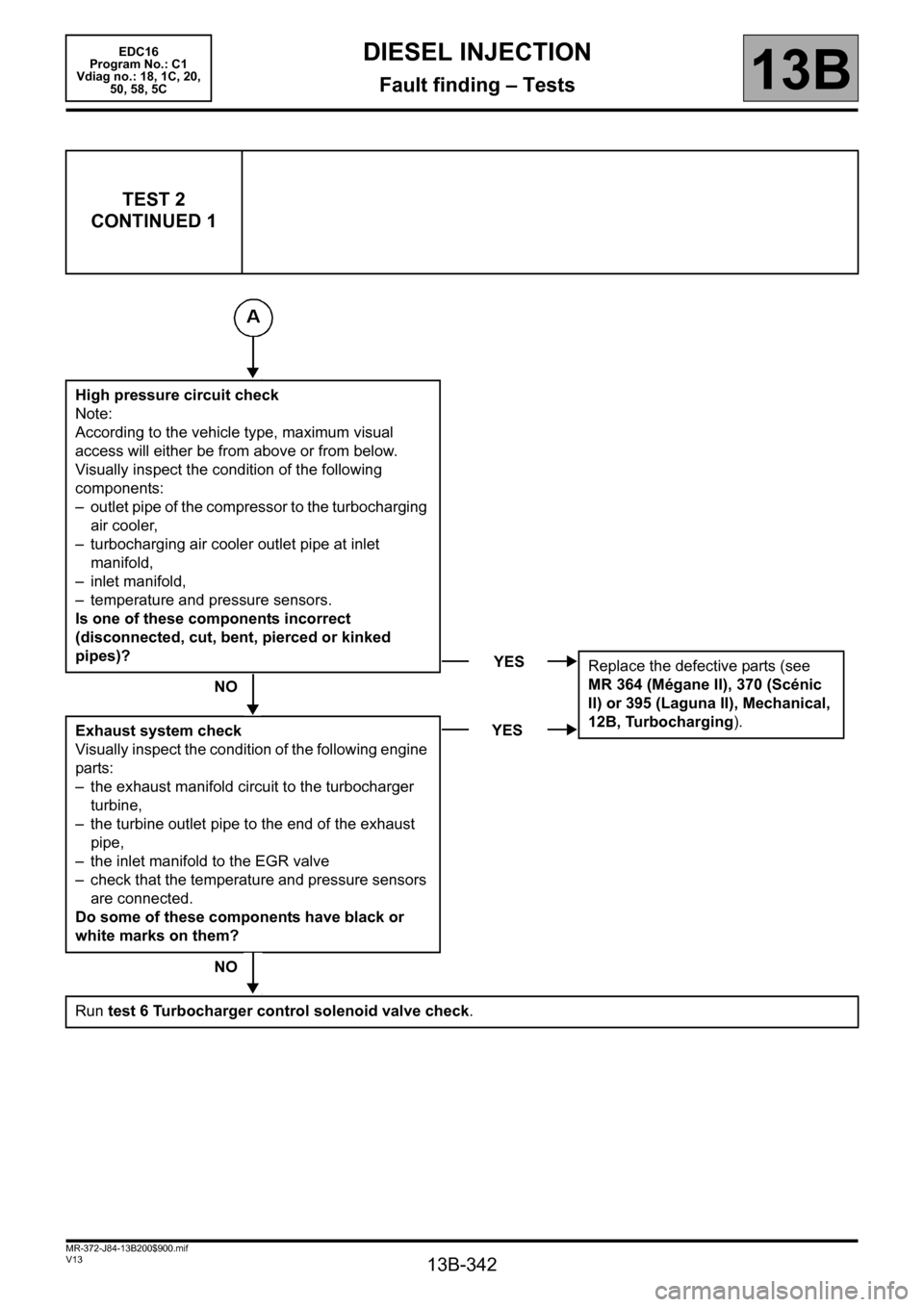
TEST 2
CONTINUED 1
High pressure circuit check
Note:
According to the vehicle type, maximum visual
access will either be from above or from below.
Visually inspect the condition of the following
components:
– outlet pipe of the compressor to the turbocharging
air cooler,
– turbocharging air cooler outlet pipe at inlet
manifold,
– inlet manifold,
– temperature and pressure sensors.
Is one of these components incorrect
(disconnected, cut, bent, pierced or kinked
pipes)?
NO
Exhaust system check
Visually inspect the condition of the following engine
parts:
– the exhaust manifold circuit to the turbocharger
turbine,
– the turbine outlet pipe to the end of the exhaust
pipe,
– the inlet manifold to the EGR valve
– check that the temperature and pressure sensors
are connected.
Do some of these components have black or
white marks on them?
NO
Run test 6 Turbocharger control solenoid valve check.
YES
Replace the defective parts (see
MR 364 (Mégane II), 370 (Scénic
II) or 395 (Laguna II), Mechanical,
12B, Turbocharging).
YES
Page 343 of 365
13B-343
MR-372-J84-13B200$900.mif
V13
EDC16
Program No.: C1
Vdiag no.: 18, 1C, 20,
50, 58, 5CDIESEL INJECTION
Fault finding – Tests13B
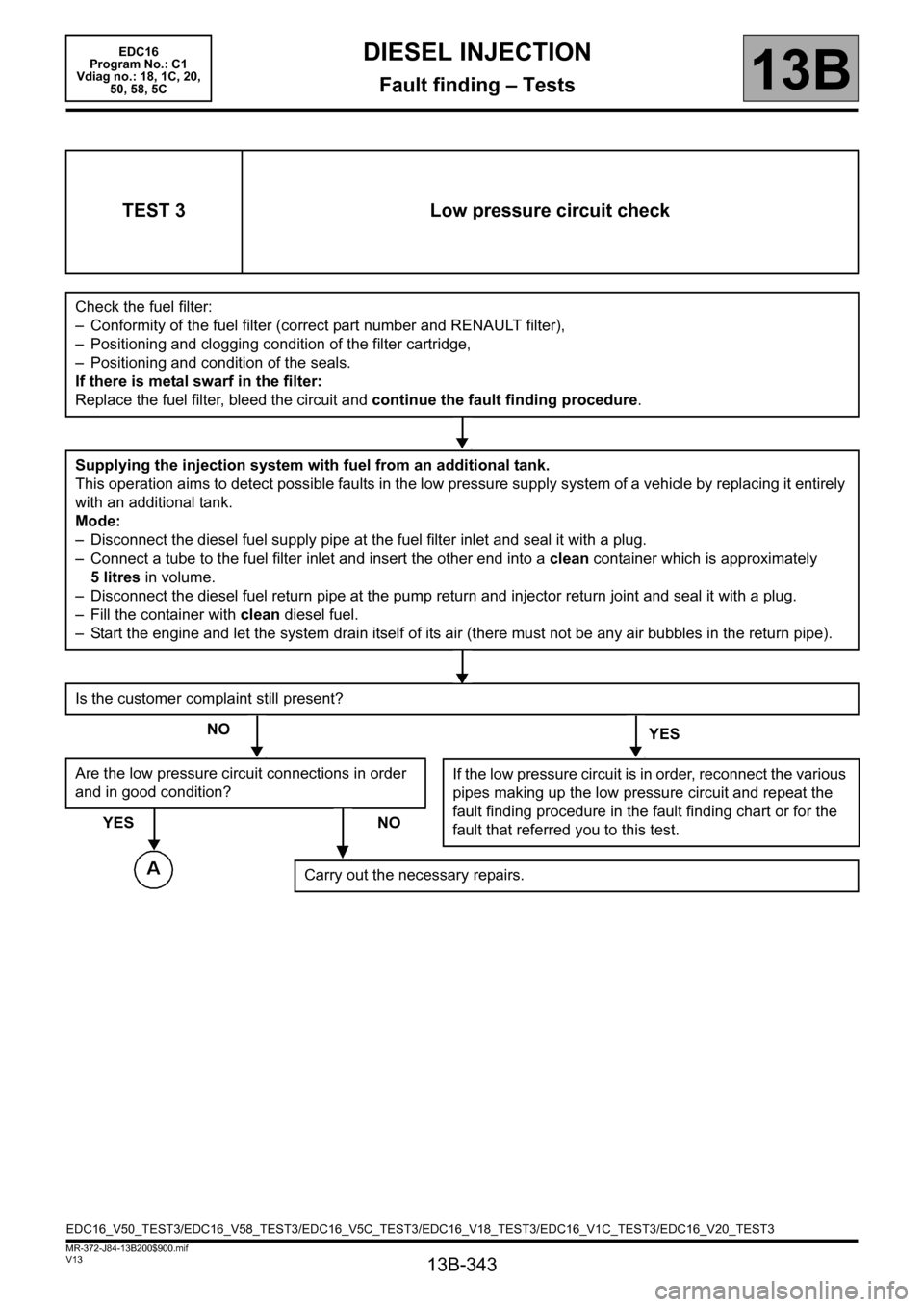
TEST 3 Low pressure circuit check
Check the fuel filter:
– Conformity of the fuel filter (correct part number and RENAULT filter),
– Positioning and clogging condition of the filter cartridge,
– Positioning and condition of the seals.
If there is metal swarf in the filter:
Replace the fuel filter, bleed the circuit and continue the fault finding procedure.
Supplying the injection system with fuel from an additional tank.
This operation aims to detect possible faults in the low pressure supply system of a vehicle by replacing it entirely
with an additional tank.
Mode:
– Disconnect the diesel fuel supply pipe at the fuel filter inlet and seal it with a plug.
– Connect a tube to the fuel filter inlet and insert the other end into a clean container which is approximately
5 litres in volume.
– Disconnect the diesel fuel return pipe at the pump return and injector return joint and seal it with a plug.
– Fill the container with clean diesel fuel.
– Start the engine and let the system drain itself of its air (there must not be any air bubbles in the return pipe).
Is the customer complaint still present?
NO
YES
Are the low pressure circuit connections in order
and in good condition?
YES NO
If the low pressure circuit is in order, reconnect the various
pipes making up the low pressure circuit and repeat the
fault finding procedure in the fault finding chart or for the
fault that referred you to this test.
Carry out the necessary repairs.
EDC16_V50_TEST3/EDC16_V58_TEST3/EDC16_V5C_TEST3/EDC16_V18_TEST3/EDC16_V1C_TEST3/EDC16_V20_TEST3
Page 344 of 365
13B-344
MR-372-J84-13B200$900.mif
V13
DIESEL INJECTION
Fault finding – Tests
EDC16
Program No.: C1
Vdiag no.: 18, 1C, 20,
50, 58, 5C
13B
TEST 3
CONTINUED
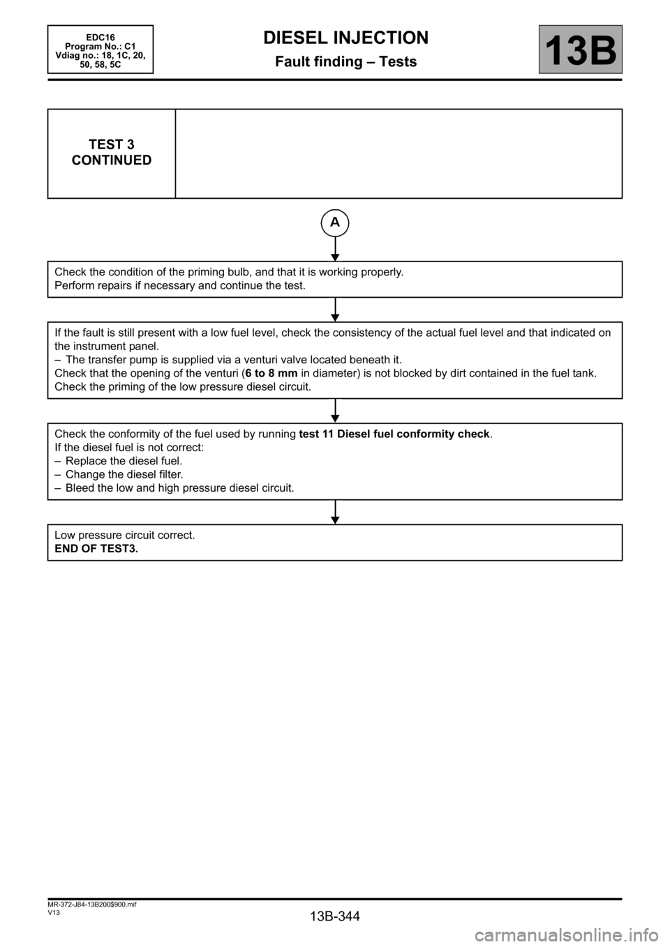
Check the condition of the priming bulb, and that it is working properly.
Perform repairs if necessary and continue the test.
If the fault is still present with a low fuel level, check the consistency of the actual fuel level and that indicated on
the instrument panel.
– The transfer pump is supplied via a venturi valve located beneath it.
Check that the opening of the venturi (6 to 8 mm in diameter) is not blocked by dirt contained in the fuel tank.
Check the priming of the low pressure diesel circuit.
Check the conformity of the fuel used by running test 11 Diesel fuel conformity check.
If the diesel fuel is not correct:
– Replace the diesel fuel.
– Change the diesel filter.
– Bleed the low and high pressure diesel circuit.
Low pressure circuit correct.
END OF TEST3.
Page 345 of 365
13B-345
MR-372-J84-13B200$900.mif
V13
DIESEL INJECTION
Fault finding – Tests
EDC16
Program No.: C1
Vdiag no.: 18, 1C, 20,
50, 58, 5C
13B
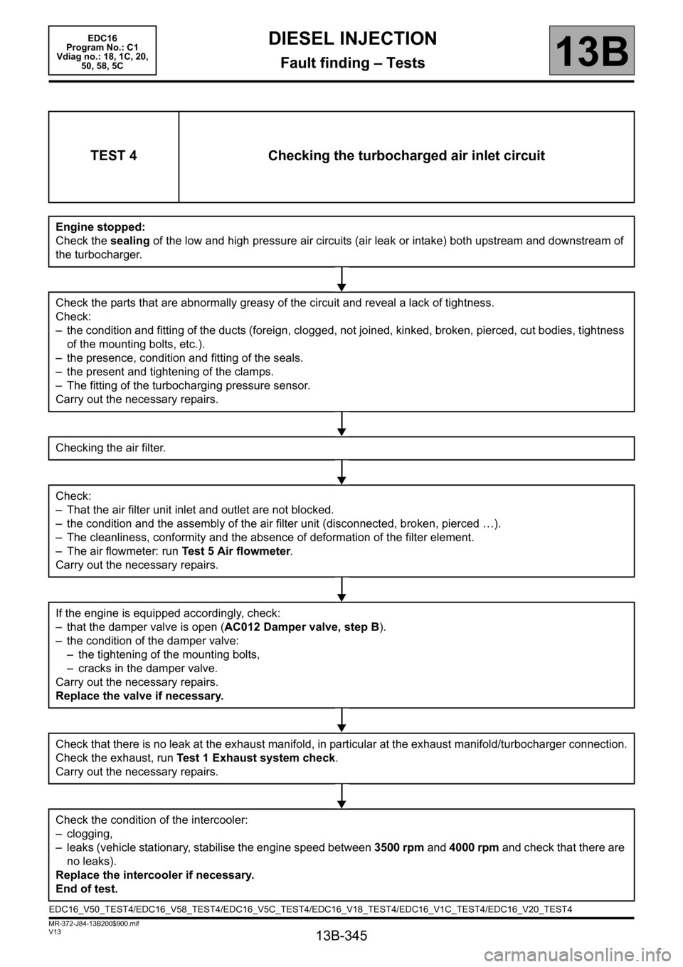
TEST 4 Checking the turbocharged air inlet circuit
Engine stopped:
Check the sealing of the low and high pressure air circuits (air leak or intake) both upstream and downstream of
the turbocharger.
Check the parts that are abnormally greasy of the circuit and reveal a lack of tightness.
Check:
– the condition and fitting of the ducts (foreign, clogged, not joined, kinked, broken, pierced, cut bodies, tightness
of the mounting bolts, etc.).
– the presence, condition and fitting of the seals.
– the present and tightening of the clamps.
– The fitting of the turbocharging pressure sensor.
Carry out the necessary repairs.
Checking the air filter.
Check:
– That the air filter unit inlet and outlet are not blocked.
– the condition and the assembly of the air filter unit (disconnected, broken, pierced …).
– The cleanliness, conformity and the absence of deformation of the filter element.
– The air flowmeter: run Test 5 Air flowmeter.
Carry out the necessary repairs.
If the engine is equipped accordingly, check:
– that the damper valve is open (AC012 Damper valve, step B).
– the condition of the damper valve:
– the tightening of the mounting bolts,
– cracks in the damper valve.
Carry out the necessary repairs.
Replace the valve if necessary.
Check that there is no leak at the exhaust manifold, in particular at the exhaust manifold/turbocharger connection.
Check the exhaust, run Test 1 Exhaust system check.
Carry out the necessary repairs.
Check the condition of the intercooler:
– clogging,
– leaks (vehicle stationary, stabilise the engine speed between 3500 rpm and 4000 rpm and check that there are
no leaks).
Replace the intercooler if necessary.
End of test.
EDC16_V50_TEST4/EDC16_V58_TEST4/EDC16_V5C_TEST4/EDC16_V18_TEST4/EDC16_V1C_TEST4/EDC16_V20_TEST4
Page 350 of 365
13B-350
MR-372-J84-13B200$936.mif
V13
DIESEL INJECTION
Fault finding – Tests
EDC16
Program No: C1
Vdiag No: 18, 1C, 20,
50, 58, 5C
13B
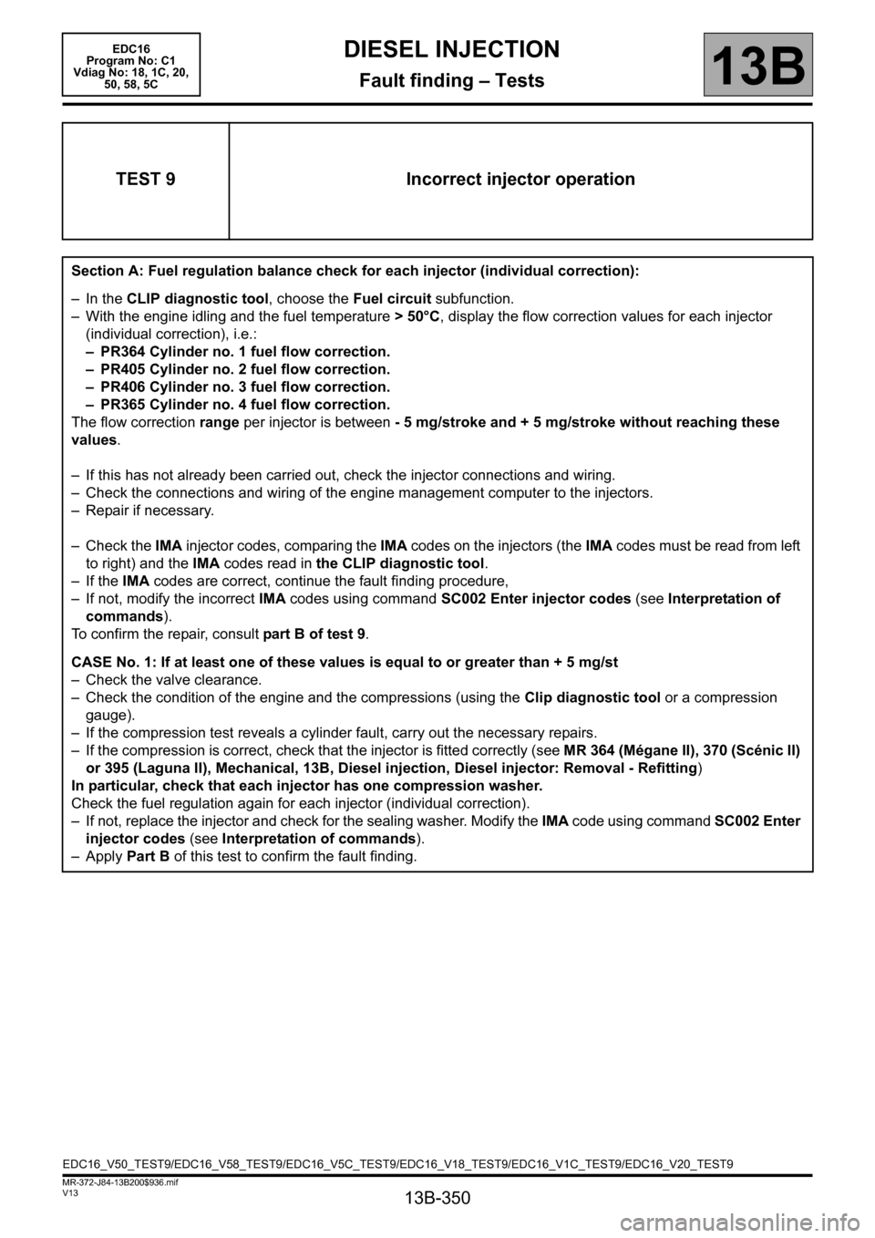
TEST 9 Incorrect injector operation
Section A: Fuel regulation balance check for each injector (individual correction):
– In the CLIP diagnostic tool, choose the Fuel circuit subfunction.
– With the engine idling and the fuel temperature > 50°C, display the flow correction values for each injector
(individual correction), i.e.:
– PR364 Cylinder no. 1 fuel flow correction.
– PR405 Cylinder no. 2 fuel flow correction.
– PR406 Cylinder no. 3 fuel flow correction.
– PR365 Cylinder no. 4 fuel flow correction.
The flow correction range per injector is between - 5 mg/stroke and + 5 mg/stroke without reaching these
values.
– If this has not already been carried out, check the injector connections and wiring.
– Check the connections and wiring of the engine management computer to the injectors.
– Repair if necessary.
– Check the IMA injector codes, comparing the IMA codes on the injectors (the IMA codes must be read from left
to right) and the IMA codes read in the CLIP diagnostic tool.
– If the IMA codes are correct, continue the fault finding procedure,
– If not, modify the incorrect IMA codes using command SC002 Enter injector codes (see Interpretation of
commands).
To confirm the repair, consult part B of test 9.
CASE No. 1: If at least one of these values is equal to or greater than + 5 mg/st
– Check the valve clearance.
– Check the condition of the engine and the compressions (using the Clip diagnostic tool or a compression
gauge).
– If the compression test reveals a cylinder fault, carry out the necessary repairs.
– If the compression is correct, check that the injector is fitted correctly (see MR 364 (Mégane II), 370 (Scénic II)
or 395 (Laguna II), Mechanical, 13B, Diesel injection, Diesel injector: Removal - Refitting)
In particular, check that each injector has one compression washer.
Check the fuel regulation again for each injector (individual correction).
– If not, replace the injector and check for the sealing washer. Modify the IMA code using command SC002 Enter
injector codes (see Interpretation of commands).
–Apply Part B of this test to confirm the fault finding.
EDC16_V50_TEST9/EDC16_V58_TEST9/EDC16_V5C_TEST9/EDC16_V18_TEST9/EDC16_V1C_TEST9/EDC16_V20_TEST9