display RENAULT SCENIC 2011 J95 / 3.G Engine And Peripherals EDC16 User Guide
[x] Cancel search | Manufacturer: RENAULT, Model Year: 2011, Model line: SCENIC, Model: RENAULT SCENIC 2011 J95 / 3.GPages: 365, PDF Size: 2.11 MB
Page 39 of 365
13B-39
MR-372-J84-13B200$252.mif
V13
DIESEL INJECTION
Fault finding – Interpretation of faults
EDC16
Program No.: C1
Vdiag no.: 18, 1C, 20,
50, 58, 5C
13B
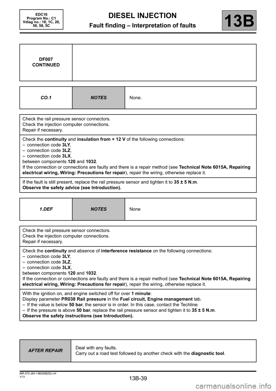
DF007
CONTINUED
CO.1
NOTESNone.
Check the rail pressure sensor connectors.
Check the injection computer connections.
Repair if necessary.
Check the continuity and insulation from + 12 V of the following connections:
– connection code 3LY,
– connection code 3LZ,
– connection code 3LX,
between components 120 and 1032.
If the connection or connections are faulty and there is a repair method (see Technical Note 6015A, Repairing
electrical wiring, Wiring: Precautions for repair), repair the wiring, otherwise replace it.
If the fault is still present, replace the rail pressure sensor and tighten it to 35 ± 5 N.m.
Observe the safety advice (see Introduction).
1.DEF
NOTESNone
Check the rail pressure sensor connectors.
Check the injection computer connections.
Repair if necessary.
Check the continuity and absence of interference resistance on the following connections:
– connection code 3LY,
– connection code 3LZ,
– connection code 3LX,
between components 120 and 1032.
If the connection or connections are faulty and there is a repair method (see Technical Note 6015A, Repairing
electrical wiring, Wiring: Precautions for repair), repair the wiring, otherwise replace it.
With the ignition on, and engine switched off for over 1 minute:
Display parameter PR038 Rail pressure in the Fuel circuit, Engine management tab.
– If the value is below 50 bar, the sensor is in order. In this case, contact the Techline.
– If the pressure is above 50 bar, replace the rail pressure sensor and tighten it to 35 ± 5 N.m.
Observe the safety instructions (see Introduction).
AFTER REPAIRDeal with any faults.
Carry out a road test followed by another check with the diagnostic tool.
Page 42 of 365
13B-42
MR-372-J84-13B200$252.mif
V13
DIESEL INJECTION
Fault finding – Interpretation of faults
EDC16
Program No.: C1
Vdiag no.: 18, 1C, 20,
50, 58, 5C
13B
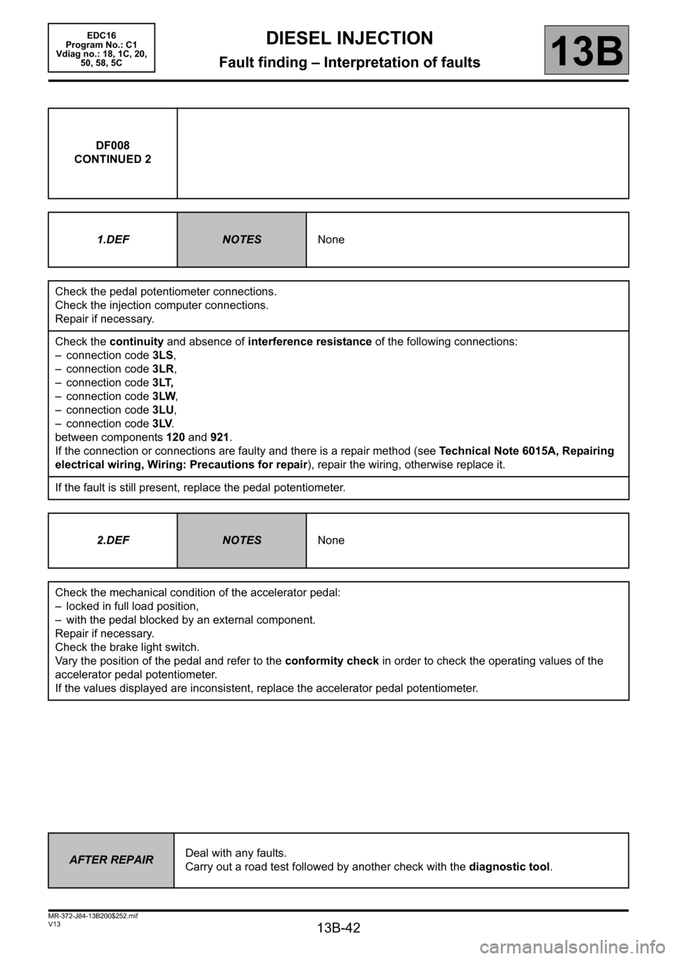
DF008
CONTINUED 2
1.DEF
NOTESNone
Check the pedal potentiometer connections.
Check the injection computer connections.
Repair if necessary.
Check the continuity and absence of interference resistance of the following connections:
– connection code 3LS,
– connection code 3LR,
– connection code 3LT,
– connection code3LW,
– connection code 3LU,
– connection code 3LV.
between components 120 and 921.
If the connection or connections are faulty and there is a repair method (see Technical Note 6015A, Repairing
electrical wiring, Wiring: Precautions for repair), repair the wiring, otherwise replace it.
If the fault is still present, replace the pedal potentiometer.
2.DEF
NOTESNone
Check the mechanical condition of the accelerator pedal:
– locked in full load position,
– with the pedal blocked by an external component.
Repair if necessary.
Check the brake light switch.
Vary the position of the pedal and refer to the conformity check in order to check the operating values of the
accelerator pedal potentiometer.
If the values displayed are inconsistent, replace the accelerator pedal potentiometer.
AFTER REPAIRDeal with any faults.
Carry out a road test followed by another check with the diagnostic tool.
Page 65 of 365
13B-65
MR-372-J84-13B200$288.mif
V13
EDC16
Program No.: C1
Vdiag no.: 18, 1C, 20,
50, 58, 5CDIESEL INJECTION
Fault finding – Interpretation of faults13B
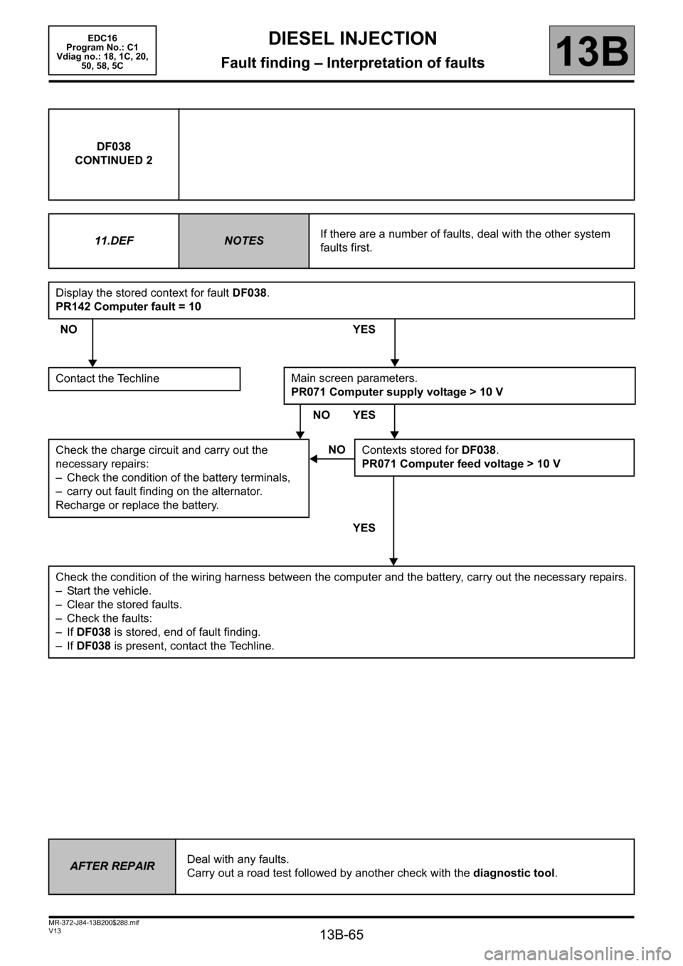
DF038
CONTINUED 2
11.DEF
NOTESIf there are a number of faults, deal with the other system
faults first.
Display the stored context for fault DF038.
PR142 Computer fault = 10
NO YES
Contact the Techline
NO YES
Check the charge circuit and carry out the
necessary repairs:
– Check the condition of the battery terminals,
– carry out fault finding on the alternator.
Recharge or replace the battery.
YES
Check the condition of the wiring harness between the computer and the battery, carry out the necessary repairs.
– Start the vehicle.
– Clear the stored faults.
– Check the faults:
– If DF038 is stored, end of fault finding.
– If DF038 is present, contact the Techline.
Main screen parameters.
PR071 Computer supply voltage > 10 V
NO
Contexts stored for DF038.
PR071 Computer feed voltage > 10 V
AFTER REPAIRDeal with any faults.
Carry out a road test followed by another check with the diagnostic tool.
Page 66 of 365
13B-66
MR-372-J84-13B200$288.mif
V13
DIESEL INJECTION
Fault finding – Interpretation of faults
EDC16
Program No.: C1
Vdiag no.: 18, 1C, 20,
50, 58, 5C
13B
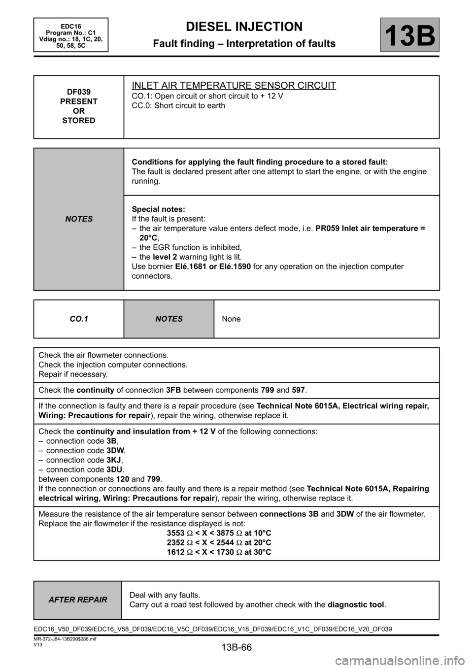
DF039
PRESENT
OR
STOREDINLET AIR TEMPERATURE SENSOR CIRCUIT
CO.1: Open circuit or short circuit to + 12 V
CC.0: Short circuit to earth
NOTESConditions for applying the fault finding procedure to a stored fault:
The fault is declared present after one attempt to start the engine, or with the engine
running.
Special notes:
If the fault is present:
– the air temperature value enters defect mode, i.e. PR059 Inlet air temperature =
20°C,
– the EGR function is inhibited,
– the level 2 warning light is lit.
Use bornier Elé.1681 or Elé.1590 for any operation on the injection computer
connectors.
CO.1
NOTESNone
Check the air flowmeter connections.
Check the injection computer connections.
Repair if necessary.
Check the continuity of connection 3FB between components 799 and 597.
If the connection is faulty and there is a repair procedure (see Technical Note 6015A, Electrical wiring repair,
Wiring: Precautions for repair), repair the wiring, otherwise replace it.
Check the continuity and insulation from + 12 V of the following connections:
– connection code 3B,
– connection code3DW,
– connection code 3KJ,
– connection code 3DU.
between components 120 and 799.
If the connection or connections are faulty and there is a repair method (see Technical Note 6015A, Repairing
electrical wiring, Wiring: Precautions for repair), repair the wiring, otherwise replace it.
Measure the resistance of the air temperature sensor between connections 3B and 3DW of the air flowmeter.
Replace the air flowmeter if the resistance displayed is not:
3553 Ω < X < 3875 Ω at 10°C
2352 Ω < X < 2544 Ω at 20°C
1612 Ω < X < 1730 Ω at 30°C
AFTER REPAIRDeal with any faults.
Carry out a road test followed by another check with the diagnostic tool.
EDC16_V50_DF039/EDC16_V58_DF039/EDC16_V5C_DF039/EDC16_V18_DF039/EDC16_V1C_DF039/EDC16_V20_DF039
Page 75 of 365
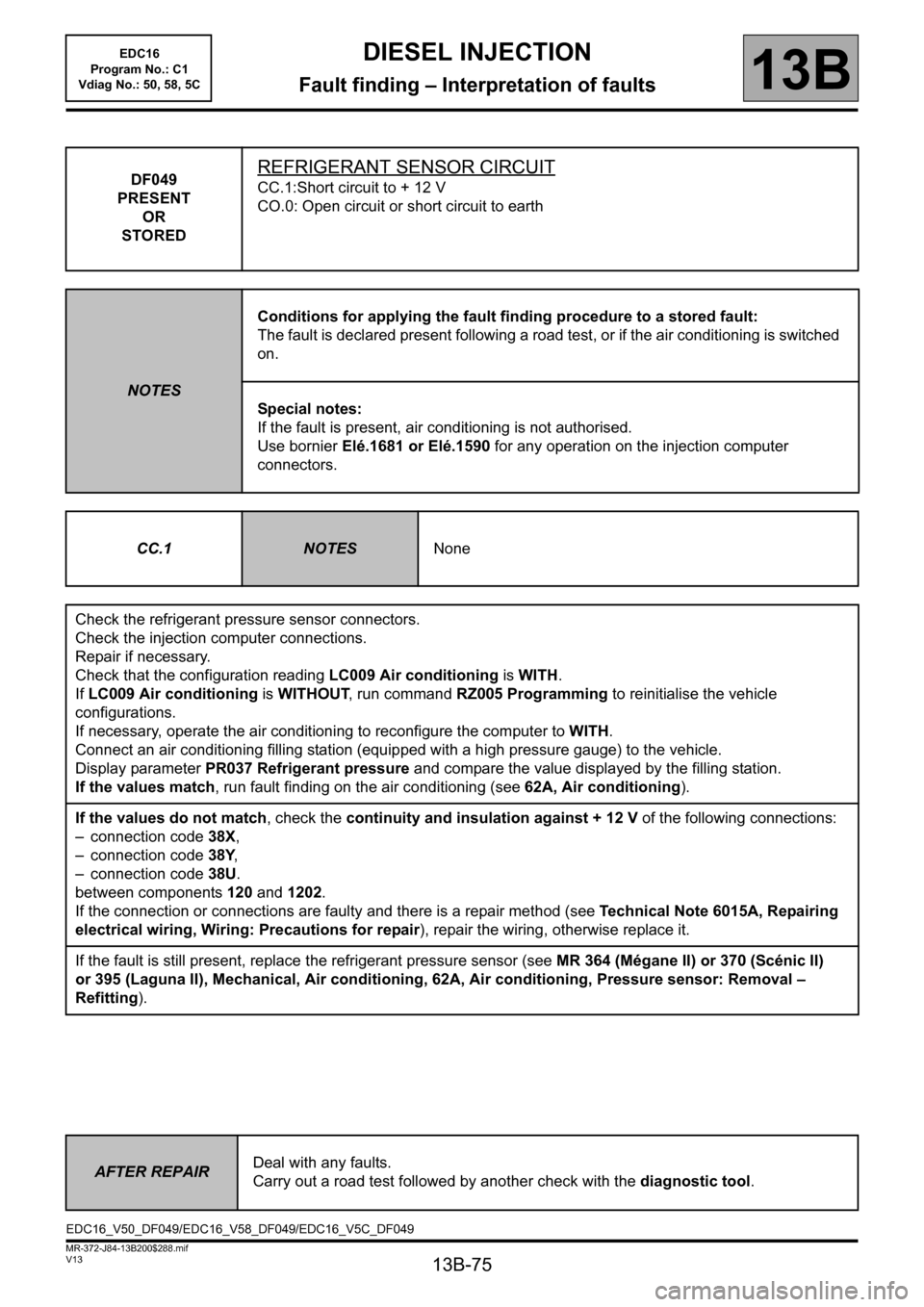
13B-75
MR-372-J84-13B200$288.mif
V13
13B
DIESEL INJECTION
Fault finding – Interpretation of faults
DF049
PRESENT
OR
STOREDREFRIGERANT SENSOR CIRCUIT
CC.1:Short circuit to + 12 V
CO.0: Open circuit or short circuit to earth
NOTESConditions for applying the fault finding procedure to a stored fault:
The fault is declared present following a road test, or if the air conditioning is switched
on.
Special notes:
If the fault is present, air conditioning is not authorised.
Use bornier Elé.1681 or Elé.1590 for any operation on the injection computer
connectors.
CC.1
NOTESNone
Check the refrigerant pressure sensor connectors.
Check the injection computer connections.
Repair if necessary.
Check that the configuration reading LC009 Air conditioning is WITH.
If LC009 Air conditioning is WITHOUT, run command RZ005 Programming to reinitialise the vehicle
configurations.
If necessary, operate the air conditioning to reconfigure the computer to WITH.
Connect an air conditioning filling station (equipped with a high pressure gauge) to the vehicle.
Display parameter PR037 Refrigerant pressure and compare the value displayed by the filling station.
If the values match, run fault finding on the air conditioning (see 62A, Air conditioning).
If the values do not match, check the continuity and insulation against + 12 V of the following connections:
– connection code 38X,
– connection code 38Y,
– connection code 38U.
between components 120 and 1202.
If the connection or connections are faulty and there is a repair method (see Technical Note 6015A, Repairing
electrical wiring, Wiring: Precautions for repair), repair the wiring, otherwise replace it.
If the fault is still present, replace the refrigerant pressure sensor (see MR 364 (Mégane II) or 370 (Scénic II)
or 395 (Laguna II), Mechanical, Air conditioning, 62A, Air conditioning, Pressure sensor: Removal –
Refitting).
AFTER REPAIRDeal with any faults.
Carry out a road test followed by another check with the diagnostic tool.
EDC16_V50_DF049/EDC16_V58_DF049/EDC16_V5C_DF049EDC16
Program No.: C1
Vdiag No.: 50, 58, 5C
Page 76 of 365
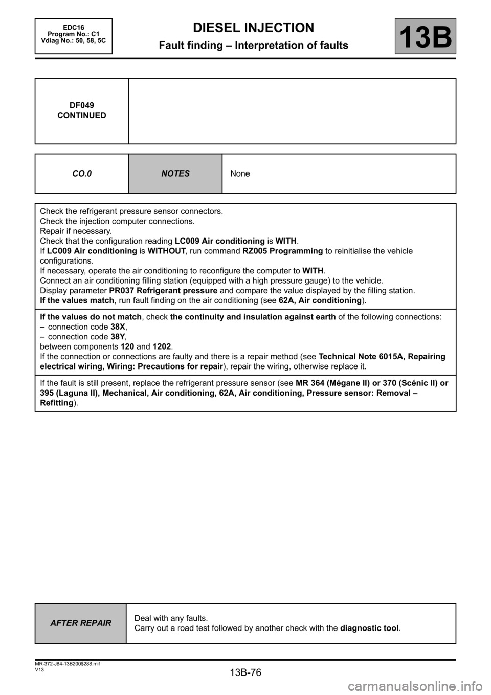
13B-76
MR-372-J84-13B200$288.mif
V13
DIESEL INJECTION
Fault finding – Interpretation of faults
EDC16
Program No.: C1
Vdiag No.: 50, 58, 5C
13B
DF049
CONTINUED
CO.0
NOTESNone
Check the refrigerant pressure sensor connectors.
Check the injection computer connections.
Repair if necessary.
Check that the configuration reading LC009 Air conditioning is WITH.
If LC009 Air conditioning is WITHOUT, run command RZ005 Programming to reinitialise the vehicle
configurations.
If necessary, operate the air conditioning to reconfigure the computer to WITH.
Connect an air conditioning filling station (equipped with a high pressure gauge) to the vehicle.
Display parameter PR037 Refrigerant pressure and compare the value displayed by the filling station.
If the values match, run fault finding on the air conditioning (see 62A, Air conditioning).
If the values do not match, check the continuity and insulation against earth of the following connections:
– connection code 38X,
– connection code 38Y,
between components 120 and 1202.
If the connection or connections are faulty and there is a repair method (see Technical Note 6015A, Repairing
electrical wiring, Wiring: Precautions for repair), repair the wiring, otherwise replace it.
If the fault is still present, replace the refrigerant pressure sensor (see MR 364 (Mégane II) or 370 (Scénic II) or
395 (Laguna II), Mechanical, Air conditioning, 62A, Air conditioning, Pressure sensor: Removal –
Refitting).
AFTER REPAIRDeal with any faults.
Carry out a road test followed by another check with the diagnostic tool.
Page 83 of 365
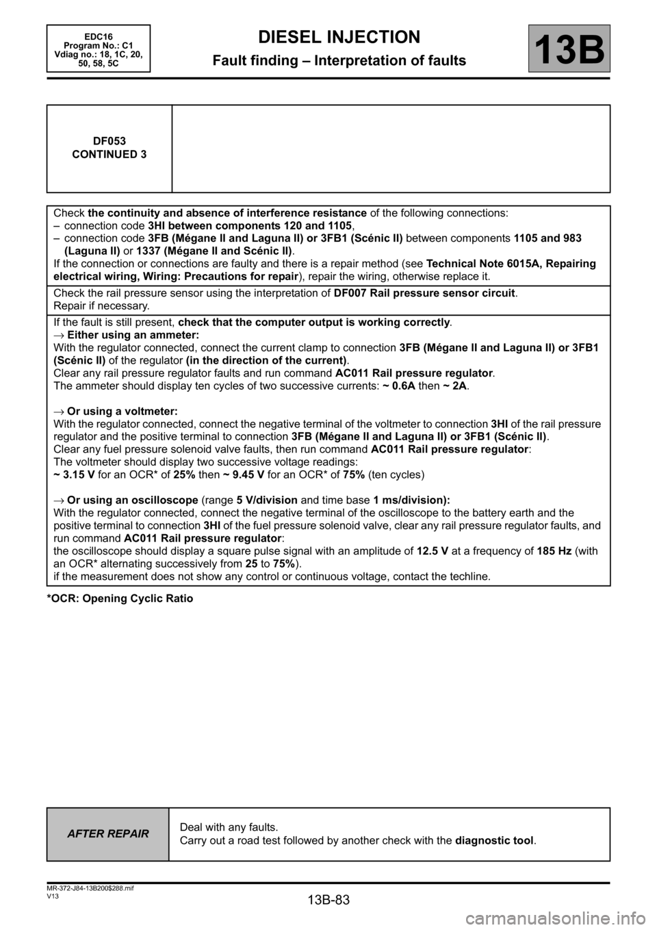
13B-83
MR-372-J84-13B200$288.mif
V13
DIESEL INJECTION
Fault finding – Interpretation of faults
EDC16
Program No.: C1
Vdiag no.: 18, 1C, 20,
50, 58, 5C
13B
*OCR: Opening Cyclic RatioDF053
CONTINUED 3
Check the continuity and absence of interference resistance of the following connections:
– connection code 3HI between components 120 and 1105,
– connection code 3FB (Mégane II and Laguna II) or 3FB1 (Scénic II) between components 1105 and 983
(Laguna II) or 1337 (Mégane II and Scénic II).
If the connection or connections are faulty and there is a repair method (see Technical Note 6015A, Repairing
electrical wiring, Wiring: Precautions for repair), repair the wiring, otherwise replace it.
Check the rail pressure sensor using the interpretation of DF007 Rail pressure sensor circuit.
Repair if necessary.
If the fault is still present, check that the computer output is working correctly.
→Either using an ammeter:
With the regulator connected, connect the current clamp to connection 3FB (Mégane II and Laguna II) or 3FB1
(Scénic II) of the regulator (in the direction of the current).
Clear any rail pressure regulator faults and run command AC011 Rail pressure regulator.
The ammeter should display ten cycles of two successive currents: ~ 0.6A then ~ 2A.
→Or using a voltmeter:
With the regulator connected, connect the negative terminal of the voltmeter to connection 3HI of the rail pressure
regulator and the positive terminal to connection 3FB (Mégane II and Laguna II) or 3FB1 (Scénic II).
Clear any fuel pressure solenoid valve faults, then run command AC011 Rail pressure regulator:
The voltmeter should display two successive voltage readings:
~3.15V for an OCR* of 25% then ~9.45V for an OCR* of 75% (ten cycles)
→Or using an oscilloscope (range 5 V/division and time base 1 ms/division):
With the regulator connected, connect the negative terminal of the oscilloscope to the battery earth and the
positive terminal to connection 3HI of the fuel pressure solenoid valve, clear any rail pressure regulator faults, and
run command AC011 Rail pressure regulator:
the oscilloscope should display a square pulse signal with an amplitude of 12.5 V at a frequency of 185 Hz (with
an OCR* alternating successively from 25 to 75%).
if the measurement does not show any control or continuous voltage, contact the techline.
AFTER REPAIRDeal with any faults.
Carry out a road test followed by another check with the diagnostic tool.
Page 86 of 365
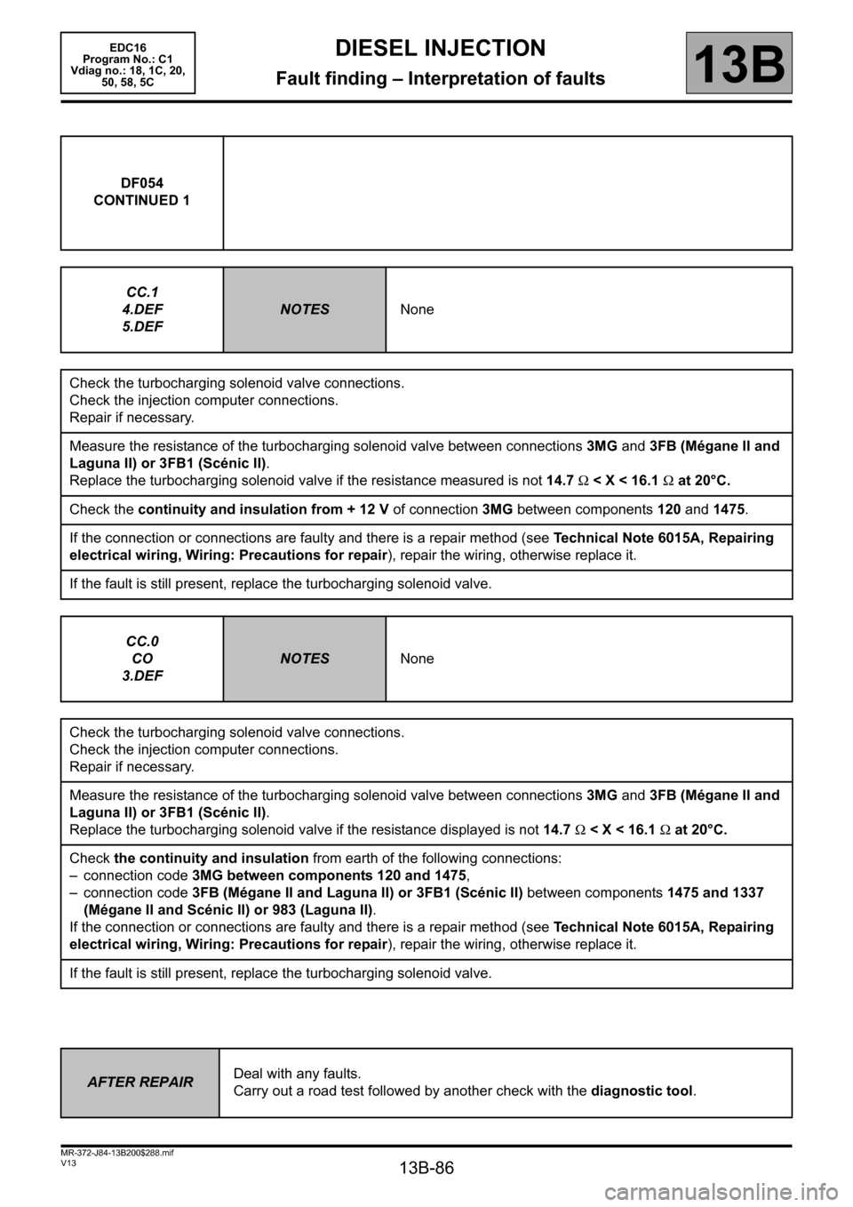
13B-86
MR-372-J84-13B200$288.mif
V13
DIESEL INJECTION
Fault finding – Interpretation of faults
EDC16
Program No.: C1
Vdiag no.: 18, 1C, 20,
50, 58, 5C
13B
DF054
CONTINUED 1
CC.1
4.DEF
5.DEF
NOTESNone
Check the turbocharging solenoid valve connections.
Check the injection computer connections.
Repair if necessary.
Measure the resistance of the turbocharging solenoid valve between connections 3MG and 3FB (Mégane II and
Laguna II) or 3FB1 (Scénic II).
Replace the turbocharging solenoid valve if the resistance measured is not 14.7 Ω < X < 16.1 Ω at 20°C.
Check the continuity and insulation from + 12 V of connection 3MG between components 120 and 1475.
If the connection or connections are faulty and there is a repair method (see Technical Note 6015A, Repairing
electrical wiring, Wiring: Precautions for repair), repair the wiring, otherwise replace it.
If the fault is still present, replace the turbocharging solenoid valve.
CC.0
CO
3.DEF
NOTESNone
Check the turbocharging solenoid valve connections.
Check the injection computer connections.
Repair if necessary.
Measure the resistance of the turbocharging solenoid valve between connections 3MG and 3FB (Mégane II and
Laguna II) or 3FB1 (Scénic II).
Replace the turbocharging solenoid valve if the resistance displayed is not 14.7 Ω < X < 16.1 Ω at 20°C.
Check the continuity and insulation from earth of the following connections:
– connection code 3MG between components 120 and 1475,
– connection code 3FB (Mégane II and Laguna II) or 3FB1 (Scénic II) between components 1475 and 1337
(Mégane II and Scénic II) or 983 (Laguna II).
If the connection or connections are faulty and there is a repair method (see Technical Note 6015A, Repairing
electrical wiring, Wiring: Precautions for repair), repair the wiring, otherwise replace it.
If the fault is still present, replace the turbocharging solenoid valve.
AFTER REPAIRDeal with any faults.
Carry out a road test followed by another check with the diagnostic tool.
Page 87 of 365
13B-87
MR-372-J84-13B200$288.mif
V13
DIESEL INJECTION
Fault finding – Interpretation of faults
EDC16
Program No.: C1
Vdiag no.: 18, 1C, 20,
50, 58, 5C
13B
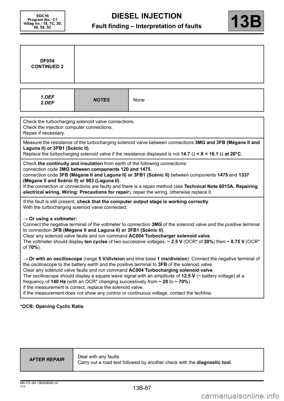
*OCR: Opening Cyclic RatioDF054
CONTINUED 2
1.DEF
2.DEF
NOTESNone
Check the turbocharging solenoid valve connections.
Check the injection computer connections.
Repair if necessary.
Measure the resistance of the turbocharging solenoid valve between connections 3MG and 3FB (Mégane II and
Laguna II) or 3FB1 (Scénic II).
Replace the turbocharging solenoid valve if the resistance displayed is not 14.7 Ω < X < 16.1 Ω at 20°C.
Check the continuity and insulation from earth of the following connections:
connection code 3MG between components 120 and 1475,
connection code 3FB (Mégane II and Laguna II) or 3FB1 (Scénic II) between components 1475 and 1337
(Mégane II and Scénic II) or 983 (Laguna II).
If the connection or connections are faulty and there is a repair method (see Technical Note 6015A, Repairing
electrical wiring, Wiring: Precautions for repair), repair the wiring, otherwise replace it.
If the fault is still present, check that the computer output stage is working correctly.
With the turbocharging solenoid valve connected:
→Or using a voltmeter:
Connect the negative terminal of the voltmeter to connection 3MG of the solenoid valve and the positive terminal
to connection 3FB (Mégane II and Laguna II) or 3FB1 (Scénic II).
Clear any solenoid valve faults and run command AC004 Turbocharger solenoid valve.
The voltmeter should display ten cycles of two successive voltages: ~2.5V (OCR* of 20%) then ~8.75V (OCR*
of 70%).
→ Or with an oscilloscope (range 5 V/division and time base 1 ms/division): Connect the negative terminal of
the oscilloscope to the battery earth and the positive terminal to 3FB of the solenoid valve.
Clear any solenoid valve faults and run command AC004 Turbocharging solenoid valve.
The oscilloscope should display a square wave signal with an amplitude of 12.5 V (~ battery voltage) at a
frequency of 140 Hz (with an OCR* changing successively from ~ 20 to ~ 70%).
if the measurement is correct, replace the solenoid valve.
if the measurement does not show any control or continuous voltage, contact the techline.
AFTER REPAIRDeal with any faults.
Carry out a road test followed by another check with the diagnostic tool.
Page 102 of 365
13B-102
MR-372-J84-13B200$324.mif
V13
DIESEL INJECTION
Fault finding – Interpretation of faults
EDC16
Program No.: C1
Vdiag no.: 18, 1C, 20,
50, 58, 5C
13B
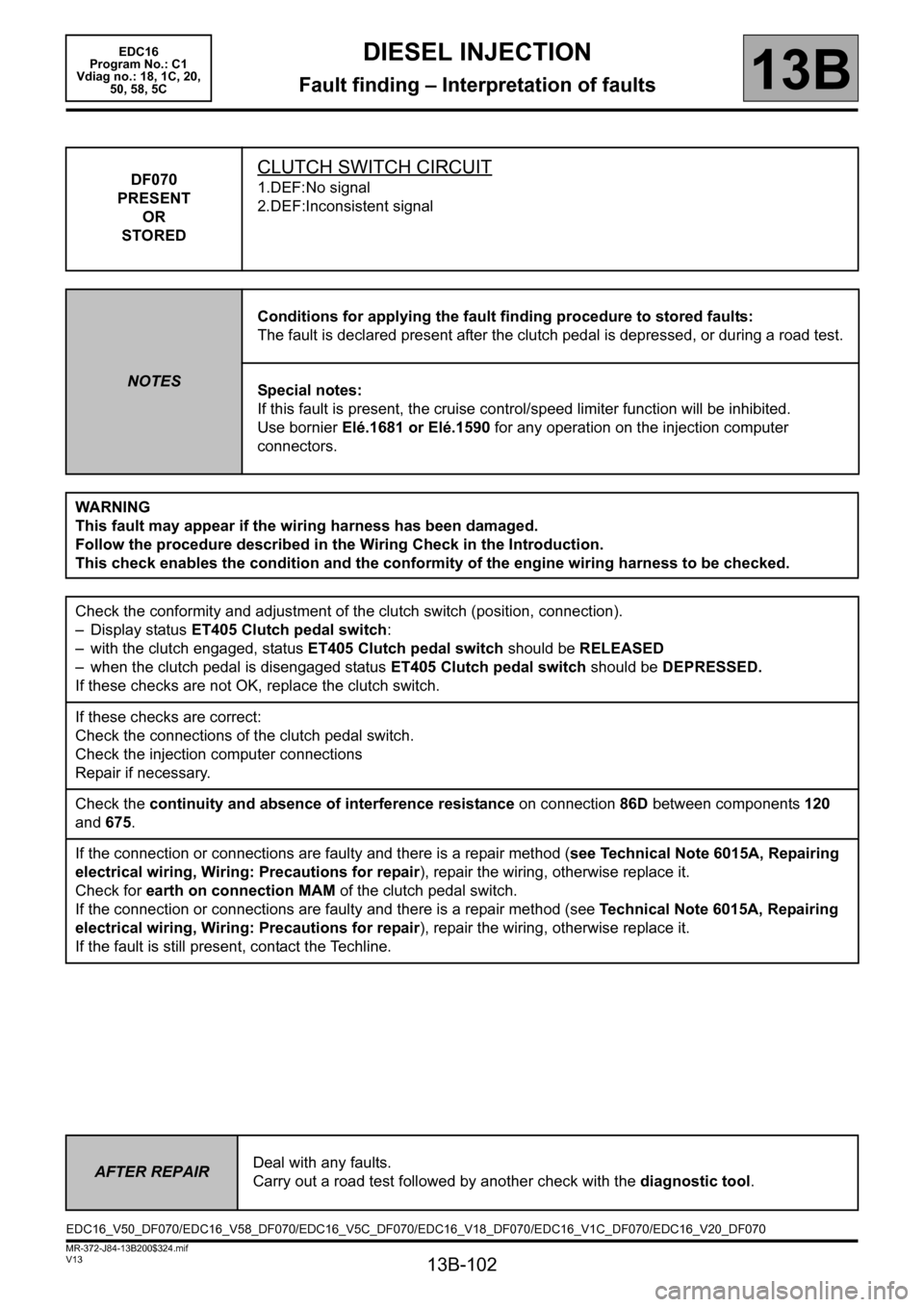
DF070
PRESENT
OR
STOREDCLUTCH SWITCH CIRCUIT
1.DEF:No signal
2.DEF:Inconsistent signal
NOTESConditions for applying the fault finding procedure to stored faults:
The fault is declared present after the clutch pedal is depressed, or during a road test.
Special notes:
If this fault is present, the cruise control/speed limiter function will be inhibited.
Use bornier Elé.1681 or Elé.1590 for any operation on the injection computer
connectors.
WARNING
This fault may appear if the wiring harness has been damaged.
Follow the procedure described in the Wiring Check in the Introduction.
This check enables the condition and the conformity of the engine wiring harness to be checked.
Check the conformity and adjustment of the clutch switch (position, connection).
– Display status ET405 Clutch pedal switch:
– with the clutch engaged, status ET405 Clutch pedal switch should be RELEASED
– when the clutch pedal is disengaged status ET405 Clutch pedal switch should be DEPRESSED.
If these checks are not OK, replace the clutch switch.
If these checks are correct:
Check the connections of the clutch pedal switch.
Check the injection computer connections
Repair if necessary.
Check the continuity and absence of interference resistance on connection 86D between components 120
and 675.
If the connection or connections are faulty and there is a repair method (see Technical Note 6015A, Repairing
electrical wiring, Wiring: Precautions for repair), repair the wiring, otherwise replace it.
Check for earth on connection MAM of the clutch pedal switch.
If the connection or connections are faulty and there is a repair method (see Technical Note 6015A, Repairing
electrical wiring, Wiring: Precautions for repair), repair the wiring, otherwise replace it.
If the fault is still present, contact the Techline.
AFTER REPAIRDeal with any faults.
Carry out a road test followed by another check with the diagnostic tool.
EDC16_V50_DF070/EDC16_V58_DF070/EDC16_V5C_DF070/EDC16_V18_DF070/EDC16_V1C_DF070/EDC16_V20_DF070