engine RENAULT SCENIC 2011 J95 / 3.G Engine And Peripherals EDC16 Workshop Manual
[x] Cancel search | Manufacturer: RENAULT, Model Year: 2011, Model line: SCENIC, Model: RENAULT SCENIC 2011 J95 / 3.GPages: 365, PDF Size: 2.11 MB
Page 290 of 365
13B-290
MR-372-J84-13B200$684.mif
V13
DIESEL INJECTION
Fault finding – Interpretation of parameters
EDC16
Program No: C1
Vdiag No: 18, 1C, 20,
50, 58, 5C
13B
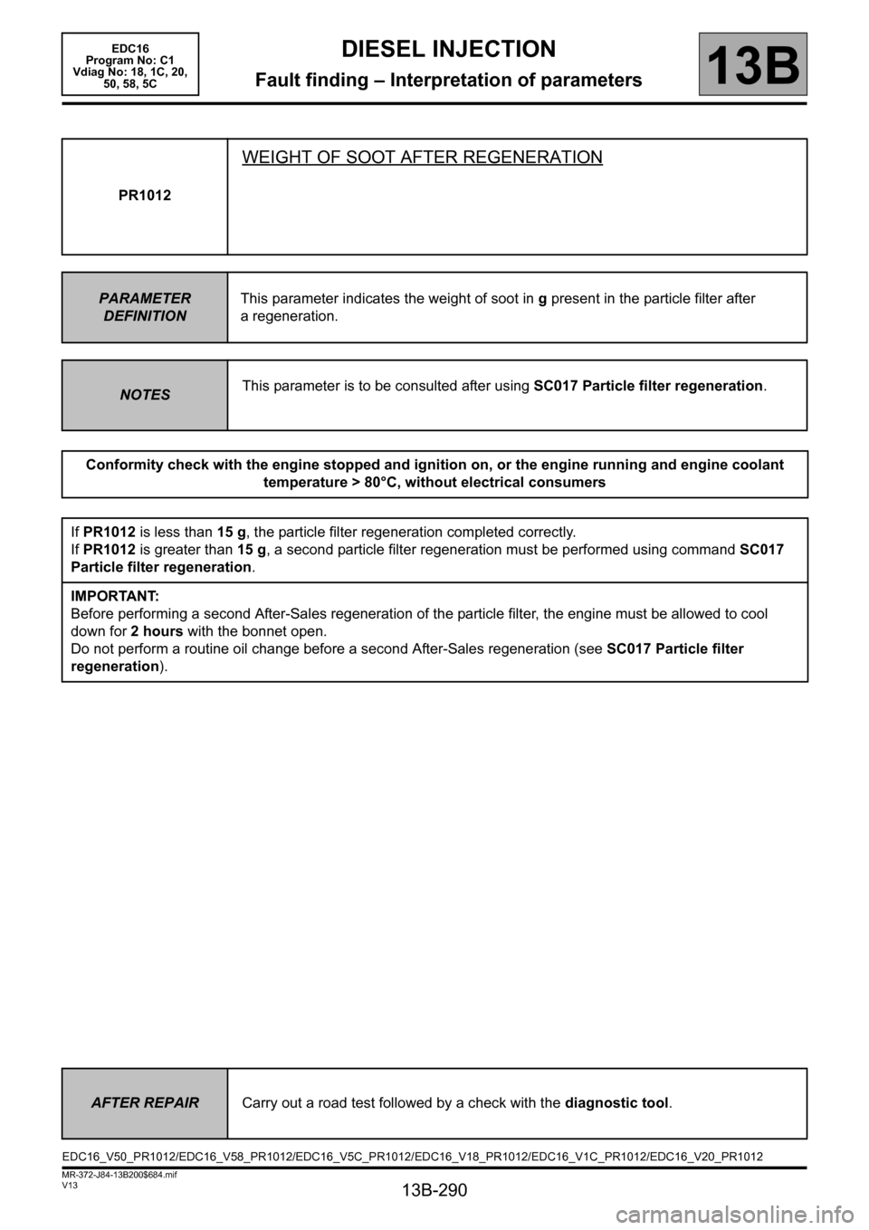
PR1012
WEIGHT OF SOOT AFTER REGENERATION
PARAMETER
DEFINITIONThis parameter indicates the weight of soot in g present in the particle filter after
a regeneration.
NOTESThis parameter is to be consulted after using SC017 Particle filter regeneration.
Conformity check with the engine stopped and ignition on, or the engine running and engine coolant
temperature > 80°C, without electrical consumers
If PR1012 is less than 15 g, the particle filter regeneration completed correctly.
If PR1012 is greater than 15 g, a second particle filter regeneration must be performed using command SC017
Particle filter regeneration.
IMPORTANT:
Before performing a second After-Sales regeneration of the particle filter, the engine must be allowed to cool
down for 2 hours with the bonnet open.
Do not perform a routine oil change before a second After-Sales regeneration (see SC017 Particle filter
regeneration).
AFTER REPAIRCarry out a road test followed by a check with the diagnostic tool.
EDC16_V50_PR1012/EDC16_V58_PR1012/EDC16_V5C_PR1012/EDC16_V18_PR1012/EDC16_V1C_PR1012/EDC16_V20_PR1012
Page 292 of 365
13B-292
MR-372-J84-13B200$756.mif
V13
13B
DIESEL INJECTION
Fault finding – Interpretation of commands
SC001
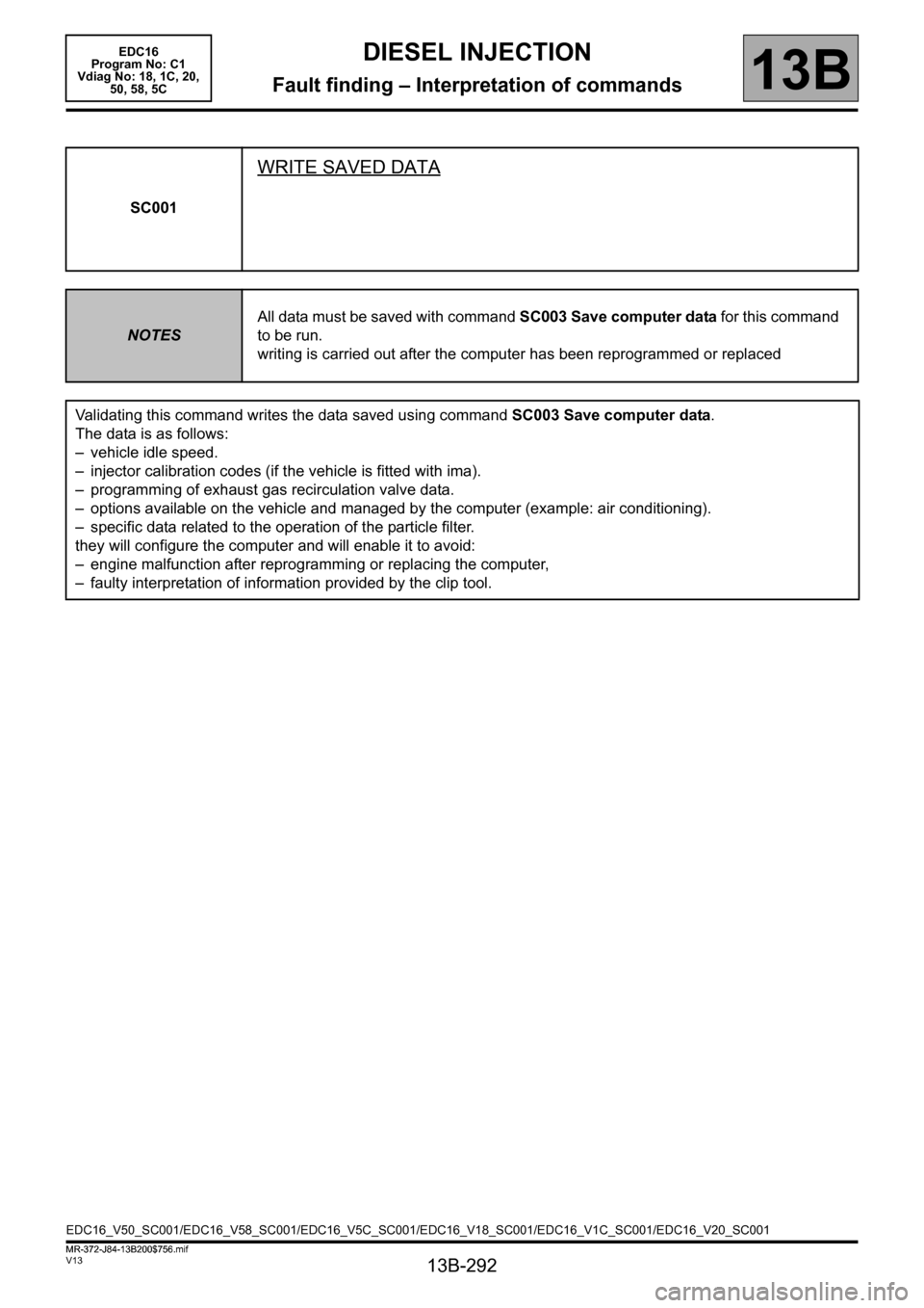
WRITE SAVED DATA
NOTESAll data must be saved with command SC003 Save computer data for this command
to be run.
writing is carried out after the computer has been reprogrammed or replaced
Validating this command writes the data saved using command SC003 Save computer data.
The data is as follows:
– vehicle idle speed.
– injector calibration codes (if the vehicle is fitted with ima).
– programming of exhaust gas recirculation valve data.
– options available on the vehicle and managed by the computer (example: air conditioning).
– specific data related to the operation of the particle filter.
they will configure the computer and will enable it to avoid:
– engine malfunction after reprogramming or replacing the computer,
– faulty interpretation of information provided by the clip tool.
EDC16_V50_SC001/EDC16_V58_SC001/EDC16_V5C_SC001/EDC16_V18_SC001/EDC16_V1C_SC001/EDC16_V20_SC001 EDC16
Program No: C1
Vdiag No: 18, 1C, 20,
50, 58, 5C
MR-372-J84-13B200$756.mif
Page 293 of 365
13B-293
MR-372-J84-13B200$756.mif
V13
DIESEL INJECTION
Fault finding – Interpretation of commands
EDC16
Program No: C1
Vdiag No: 18, 1C, 20,
50, 58, 5C
13B
SC002
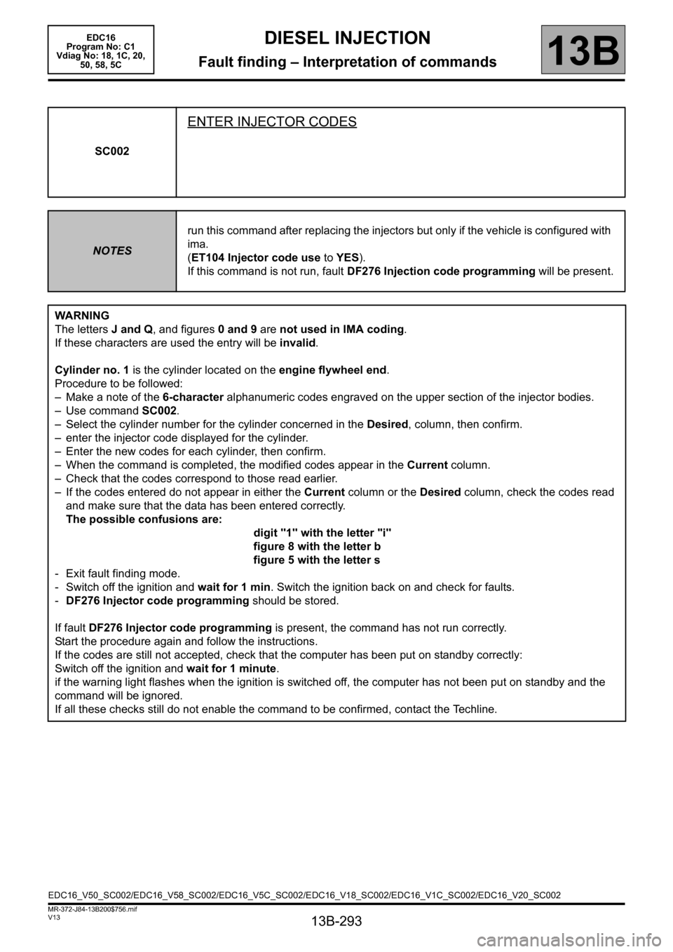
ENTER INJECTOR CODES
NOTESrun this command after replacing the injectors but only if the vehicle is configured with
ima.
(ET104 Injector code use to YES).
If this command is not run, fault DF276 Injection code programming will be present.
WARNING
The letters J and Q, and figures 0 and 9 are not used in IMA coding.
If these characters are used the entry will be invalid.
Cylinder no. 1 is the cylinder located on the engine flywheel end.
Procedure to be followed:
– Make a note of the 6-character alphanumeric codes engraved on the upper section of the injector bodies.
– Use command SC002.
– Select the cylinder number for the cylinder concerned in the Desired, column, then confirm.
– enter the injector code displayed for the cylinder.
– Enter the new codes for each cylinder, then confirm.
– When the command is completed, the modified codes appear in the Current column.
– Check that the codes correspond to those read earlier.
– If the codes entered do not appear in either the Current column or the Desired column, check the codes read
and make sure that the data has been entered correctly.
The possible confusions are:
digit "1" with the letter "i"
figure 8 with the letter b
figure 5 with the letter s
- Exit fault finding mode.
- Switch off the ignition and wait for 1 min. Switch the ignition back on and check for faults.
-DF276 Injector code programming should be stored.
If fault DF276 Injector code programming is present, the command has not run correctly.
Start the procedure again and follow the instructions.
If the codes are still not accepted, check that the computer has been put on standby correctly:
Switch off the ignition and wait for 1 minute.
if the warning light flashes when the ignition is switched off, the computer has not been put on standby and the
command will be ignored.
If all these checks still do not enable the command to be confirmed, contact the Techline.
EDC16_V50_SC002/EDC16_V58_SC002/EDC16_V5C_SC002/EDC16_V18_SC002/EDC16_V1C_SC002/EDC16_V20_SC002
Page 295 of 365
13B-295
MR-372-J84-13B200$756.mif
V13
DIESEL INJECTION
Fault finding – Interpretation of commands
EDC16
Program No: C1
Vdiag No: 18, 1C, 20,
50, 58, 5C
13B
SC017
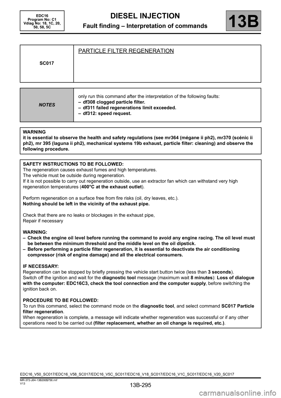
PARTICLE FILTER REGENERATION
NOTESonly run this command after the interpretation of the following faults:
– df308 clogged particle filter.
– df311 failed regenerations limit exceeded.
– df312: speed request.
WARNING
it is essential to observe the health and safety regulations (see mr364 (mégane ii ph2), mr370 (scénic ii
ph2), mr 395 (laguna ii ph2), mechanical systems 19b exhaust, particle filter: cleaning) and observe the
following procedure.
SAFETY INSTRUCTIONS TO BE FOLLOWED:
The regeneration causes exhaust fumes and high temperatures.
The vehicle must be outside during regeneration.
If it is not possible to carry out regeneration outside, use an extractor fan which can withstand very high
regeneration temperatures (400°C at the exhaust outlet).
Perform regeneration on a surface free from fire risks (oil, dry leaves, etc.).
Nothing should be left in the vicinity of the exhaust pipe.
Check that there are no leaks or blockages in the exhaust pipe,
Repair if necessary
WARNING:
– Check the engine oil level before running the command to avoid any engine racing. The oil level must
be between the minimum threshold and the middle level on the oil dipstick.
– Before performing a particle filter regeneration, it is essential to deactivate the air conditioning
compressor (risk of engine damage) and all the electrical consumers.
IF NECESSARY:
Regeneration can be stopped by briefly pressing the vehicle start button twice (less than 3 seconds).
Switch off the ignition and wait for the diagnostic tool message (maximum wait 8 minutes): Loss of dialogue
with the computer: EDC16C3, check the tool connection and the computer supply, before switching the
ignition back on.
PROCEDURE TO BE FOLLOWED:
To run this command, select the command mode on the diagnostic tool, and select command SC017 Particle
filter regeneration.
When regeneration is complete, a message will indicate whether regeneration was successful or if any other
operations need to be carried out (filter replacement, whether an oil change is required, etc.).
EDC16_V50_SC017/EDC16_V58_SC017/EDC16_V5C_SC017/EDC16_V18_SC017/EDC16_V1C_SC017/EDC16_V20_SC017
Page 296 of 365
13B-296
MR-372-J84-13B200$756.mif
V13
DIESEL INJECTION
Fault finding – Interpretation of commands
EDC16
Program No: C1
Vdiag No: 18, 1C, 20,
50, 58, 5C
13B
SC017
CONTINUED 1
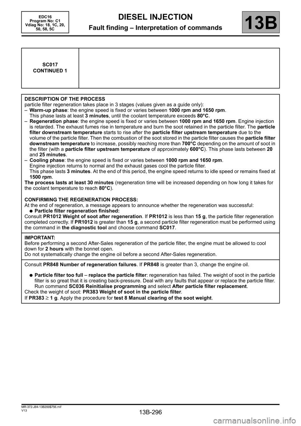
DESCRIPTION OF THE PROCESS
particle filter regeneration takes place in 3 stages (values given as a guide only):
–Warm-up phase: the engine speed is fixed or varies between 1000 rpm and 1650 rpm.
This phase lasts at least 3 minutes, until the coolant temperature exceeds 80°C.
–Regeneration phase: the engine speed is fixed or varies between 1000 rpm and 1650 rpm. Engine injection
is retarded. The exhaust fumes rise in temperature and burn the soot retained in the particle filter. The particle
filter downstream temperature starts to rise after the particle filter upstream temperature due to the
volume of the particle filter. Then the combustion of the soot stored in the particle filter causes the particle filter
downstream temperature to increase, possibly reaching more than 700°C depending on the amount of soot in
the filter (with a particle filter upstream temperature of approximately 600°C). This phase lasts between 20
and 25 minutes.
–Cooling phase: the engine speed is fixed or varies between 1000 rpm and 1650 rpm.
Engine injection returns to normal and the exhaust gases cool the particle filter.
This phase lasts 3 minutes. At the end of this period, the engine speed returns to idle speed or remains fixed at
1500 rpm.
The process lasts at least 30 minutes (regeneration time will be increased depending on how long it takes for
the coolant temperature to reach 80°C).
CONFIRMING THE REGENERATION PROCESS:
At the end of regeneration, a message appears to announce whether the regeneration was successful:
●Particle filter regeneration finished:
Consult PR1012 Weight of soot after regeneration. If PR1012 is less than 15 g, the particle filter regeneration
completed correctly. If PR1012 is greater than 15 g, a second particle filter regeneration must be performed using
the command in the diagnostic tool and choose command SC017.
IMPORTANT:
Before performing a second After-Sales regeneration of the particle filter, the engine must be allowed to cool
down for 2 hours with the bonnet open.
Do not systematically change the engine oil before a second After-Sales regeneration.
Consult PR848 Number of regeneration failures. If PR848 is greater than 3, change the engine oil.
●Particle filter too full – replace the particle filter: regeneration has failed. The weight of soot in the particle
filter is so great that it is creating back-pressure. Deal with any faults that appear or replace the particle filter.
Run command SC036 Reinitialise programming and select After particle filter replacement.
Check the weight of soot: PR383 Weight of soot in the particle filter.
If PR383
≥ 1 g. Apply the procedure for test 8 Manual clearing of the soot weight.
Page 297 of 365
13B-297
MR-372-J84-13B200$756.mif
V13
DIESEL INJECTION
Fault finding – Interpretation of commands
EDC16
Program No: C1
Vdiag No: 18, 1C, 20,
50, 58, 5C
13B
SC017
CONTINUED 2
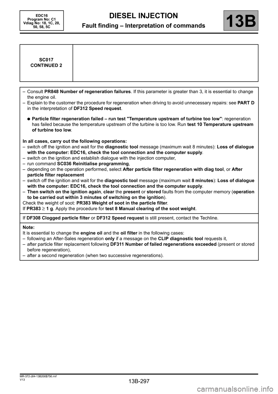
–Consult PR848 Number of regeneration failures. If this parameter is greater than 3, it is essential to change
the engine oil.
– Explain to the customer the procedure for regeneration when driving to avoid unnecessary repairs: see PART D
in the interpretation of DF312 Speed request.
●Particle filter regeneration failed – run test "Temperature upstream of turbine too low": regeneration
has failed because the temperature upstream of the turbine is too low. Run test 10 Temperature upstream
of turbine too low.
In all cases, carry out the following operations:
– switch off the ignition and wait for the diagnostic tool message (maximum wait 8 minutes): Loss of dialogue
with the computer: EDC16, check the tool connection and the computer supply.
– switch on the ignition and establish dialogue with the injection computer,
– run command SC036 Reinitialise programming,
– depending on the operation performed, select After particle filter regeneration with diag tool, or After
particle filter replacement
– switch off the ignition and wait for the diagnostic tool message (maximum wait 8 minutes): Loss of dialogue
with the computer: EDC16, check the tool connection and the computer supply.
–Then switch on the ignition again, clear the present or stored faults from the computer memory (operation
to be carried out within 3 minutes of switching on the ignition).
Check the weight of soot: PR383 Weight of soot in the particle filter.
If PR383
≥ 1 g. Apply the procedure for test 8 Manual clearing of the soot weight.
If DF308 Clogged particle filter or DF312 Speed request is still present, contact the Techline.
Note:
It is essential to change the engine oil and the oil filter in the following cases:
– following an After-Sales regeneration only if a message on the CLIP diagnostic tool requests it,
– after particle filter replacement following DF311 Number of failed regenerations exceeded (present or stored
before regeneration),
– after a second regeneration (when two successive regenerations).
Page 298 of 365
13B-298
MR-372-J84-13B200$756.mif
V13
DIESEL INJECTION
Fault finding – Interpretation of commands
EDC16
Program No: C1
Vdiag No: 18, 1C, 20,
50, 58, 5C
13B
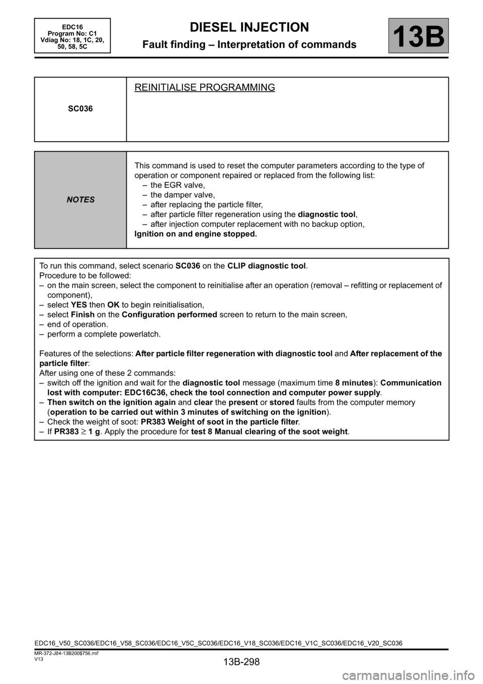
SC036
REINITIALISE PROGRAMMING
NOTESThis command is used to reset the computer parameters according to the type of
operation or component repaired or replaced from the following list:
– the EGR valve,
– the damper valve,
– after replacing the particle filter,
– after particle filter regeneration using the diagnostic tool,
– after injection computer replacement with no backup option,
Ignition on and engine stopped.
To run this command, select scenario SC036 on the CLIP diagnostic tool.
Procedure to be followed:
– on the main screen, select the component to reinitialise after an operation (removal – refitting or replacement of
component),
–select YES then OK to begin reinitialisation,
–select Finish on the Configuration performed screen to return to the main screen,
– end of operation.
– perform a complete powerlatch.
Features of the selections: After particle filter regeneration with diagnostic tool and After replacement of the
particle filter:
After using one of these 2 commands:
– switch off the ignition and wait for the diagnostic tool message (maximum time 8 minutes): Communication
lost with computer: EDC16C36, check the tool connection and computer power supply.
–Then switch on the ignition again and clear the present or stored faults from the computer memory
(operation to be carried out within 3 minutes of switching on the ignition).
– Check the weight of soot: PR383 Weight of soot in the particle filter.
– If PR383
≥ 1 g. Apply the procedure for test 8 Manual clearing of the soot weight.
EDC16_V50_SC036/EDC16_V58_SC036/EDC16_V5C_SC036/EDC16_V18_SC036/EDC16_V1C_SC036/EDC16_V20_SC036
Page 301 of 365

13B-301
MR-372-J84-13B200$756.mif
V13
DIESEL INJECTION
Fault finding – Interpretation of commands
EDC16
Program No: C1
Vdiag No: 18, 1C, 20,
50, 58, 5C
13B
RZ034
COMPUTER MEMORY
NOTESIMPORTANT
Only use this command if DF038 Computer memory is present.
Ignition on and engine stopped.
Command RZ034 is used to reinitialise the computer memory.
With the ignition on:
●Use command RZ034.
●Switch off the ignition and wait for the message Communication lost with computer.
●Switch on the ignition again.
●Run the programming commands (see Configuration and programming)
●Switch off the ignition and wait for the message Communication lost with computer.
Perform a road test to reinitialise the vehicle parameters.
EDC16_V50_RZ034/EDC16_V58_RZ034/EDC16_V5C_RZ034/EDC16_V18_RZ034/EDC16_V1C_RZ034/EDC16_V20_RZ034
Page 303 of 365
13B-303
MR-372-J84-13B200$756.mif
V13
DIESEL INJECTION
Fault finding – Interpretation of commands
EDC16
Program No: C1
Vdiag No: 18, 1C, 20,
50, 58, 5C
13B
AC004
TURBOCHARGING SOLENOID VALVE
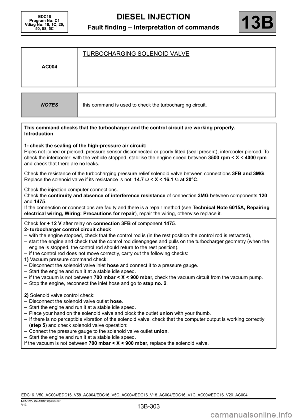
NOTESthis command is used to check the turbocharging circuit.
This command checks that the turbocharger and the control circuit are working properly.
Introduction
1- check the sealing of the high-pressure air circuit:
Pipes not joined or pierced, pressure sensor disconnected or poorly fitted (seal present), intercooler pierced. To
check the intercooler: with the vehicle stopped, stabilise the engine speed between 3500 rpm < X < 4000 rpm
and check that there are no leaks.
Check the resistance of the turbocharging pressure relief solenoid valve between connections 3FB and 3MG.
Replace the solenoid valve if its resistance is not: 14.7 Ω < X < 16.1 Ω at 20°C.
Check the injection computer connections.
Check the continuity and absence of interference resistance of connection 3MG between components 120
and 1475.
If the connection or connections are faulty and there is a repair method (see Technical Note 6015A, Repairing
electrical wiring, Wiring: Precautions for repair), repair the wiring, otherwise replace it.
Check for + 12 V after relay on connection 3FB of component 1475.
2- turbocharger control circuit check
– with the engine stopped, check that the control rod is (in the rest position the control rod is retracted),
– start the engine and check that the control rod disengages and pulls on the turbocharger geometry (when the
engine is stopped, the control rod should return to the rest position).
– if the control rod does not move correctly, carry out the following checks:
1) Vacuum pressure command check:
– Disconnect the solenoid valve inlet hose and connect it to a pressure gauge.
– Start the engine and run it at a stable idle speed.
– if the vacuum is not between 700 mbar < X < 900 mbar, check the vacuum circuit from the vacuum pump.
– Stop the engine, reconnect the inlet hose and go to step no. 2.
2) Solenoid valve control check:
– Disconnect the solenoid valve outlet hose.
– Start the engine and run it at a stable idle speed.
– Place your hand on the solenoid valve and block the outlet union with your thumb.
– If there is no perceptible vibration of the solenoid valve, check that the computer output is working correctly
(step 5) and check solenoid valve operation:
– Connect the pressure gauge to the solenoid valve outlet union.
– Start the engine and run it at a stable idle speed.
if the vacuum is not between 700 mbar < X < 900 mbar, replace the solenoid valve.
EDC16_V50_AC004/EDC16_V58_AC004/EDC16_V5C_AC004/EDC16_V18_AC004/EDC16_V1C_AC004/EDC16_V20_AC004
Page 304 of 365
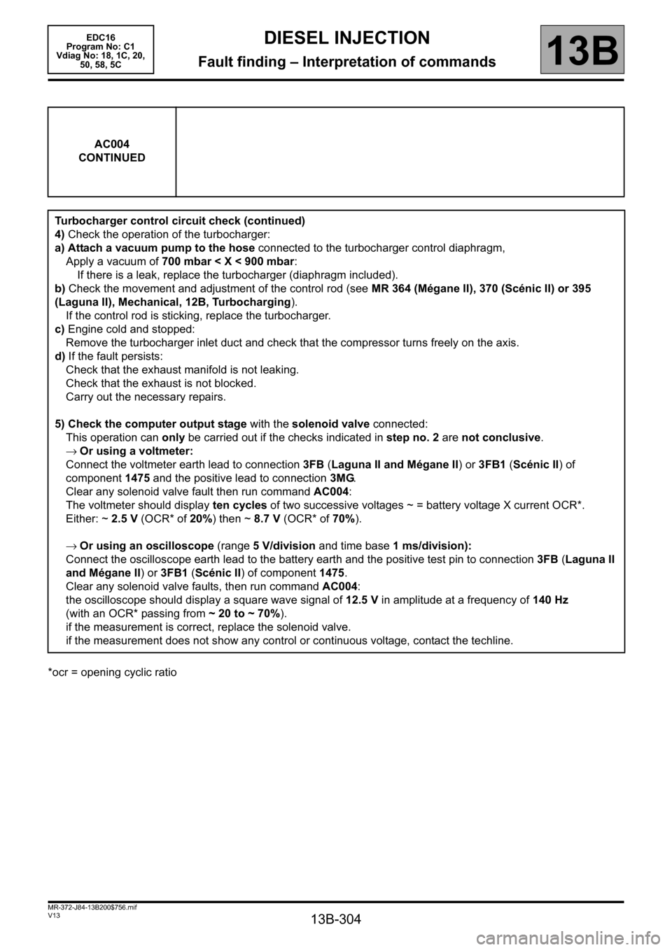
13B-304
MR-372-J84-13B200$756.mif
V13
DIESEL INJECTION
Fault finding – Interpretation of commands
EDC16
Program No: C1
Vdiag No: 18, 1C, 20,
50, 58, 5C
13B
*ocr = opening cyclic ratioAC004
CONTINUED
Turbocharger control circuit check (continued)
4) Check the operation of the turbocharger:
a) Attach a vacuum pump to the hose connected to the turbocharger control diaphragm,
Apply a vacuum of 700 mbar < X < 900 mbar:
If there is a leak, replace the turbocharger (diaphragm included).
b) Check the movement and adjustment of the control rod (see MR 364 (Mégane II), 370 (Scénic II) or 395
(Laguna II), Mechanical, 12B, Turbocharging).
If the control rod is sticking, replace the turbocharger.
c) Engine cold and stopped:
Remove the turbocharger inlet duct and check that the compressor turns freely on the axis.
d) If the fault persists:
Check that the exhaust manifold is not leaking.
Check that the exhaust is not blocked.
Carry out the necessary repairs.
5) Check the computer output stage with the solenoid valve connected:
This operation can only be carried out if the checks indicated in step no. 2 are not conclusive.
→Or using a voltmeter:
Connect the voltmeter earth lead to connection 3FB (Laguna II and Mégane II) or 3FB1 (Scénic II) of
component 1475 and the positive lead to connection 3MG.
Clear any solenoid valve fault then run command AC004:
The voltmeter should display ten cycles of two successive voltages ~ = battery voltage X current OCR*.
Either: ~ 2.5 V (OCR* of 20%) then ~ 8.7 V (OCR* of 70%).
→Or using an oscilloscope (range 5 V/division and time base 1 ms/division):
Connect the oscilloscope earth lead to the battery earth and the positive test pin to connection 3FB (Laguna II
and Mégane II) or 3FB1 (Scénic II) of component 1475.
Clear any solenoid valve faults, then run command AC004:
the oscilloscope should display a square wave signal of 12.5 V in amplitude at a frequency of 140 Hz
(with an OCR* passing from ~ 20 to ~ 70%).
if the measurement is correct, replace the solenoid valve.
if the measurement does not show any control or continuous voltage, contact the techline.