engine RENAULT SCENIC 2011 J95 / 3.G Engine And Peripherals EDC16 Workshop Manual
[x] Cancel search | Manufacturer: RENAULT, Model Year: 2011, Model line: SCENIC, Model: RENAULT SCENIC 2011 J95 / 3.GPages: 365, PDF Size: 2.11 MB
Page 345 of 365
13B-345
MR-372-J84-13B200$900.mif
V13
DIESEL INJECTION
Fault finding – Tests
EDC16
Program No.: C1
Vdiag no.: 18, 1C, 20,
50, 58, 5C
13B
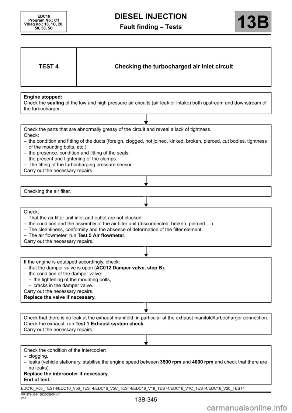
TEST 4 Checking the turbocharged air inlet circuit
Engine stopped:
Check the sealing of the low and high pressure air circuits (air leak or intake) both upstream and downstream of
the turbocharger.
Check the parts that are abnormally greasy of the circuit and reveal a lack of tightness.
Check:
– the condition and fitting of the ducts (foreign, clogged, not joined, kinked, broken, pierced, cut bodies, tightness
of the mounting bolts, etc.).
– the presence, condition and fitting of the seals.
– the present and tightening of the clamps.
– The fitting of the turbocharging pressure sensor.
Carry out the necessary repairs.
Checking the air filter.
Check:
– That the air filter unit inlet and outlet are not blocked.
– the condition and the assembly of the air filter unit (disconnected, broken, pierced …).
– The cleanliness, conformity and the absence of deformation of the filter element.
– The air flowmeter: run Test 5 Air flowmeter.
Carry out the necessary repairs.
If the engine is equipped accordingly, check:
– that the damper valve is open (AC012 Damper valve, step B).
– the condition of the damper valve:
– the tightening of the mounting bolts,
– cracks in the damper valve.
Carry out the necessary repairs.
Replace the valve if necessary.
Check that there is no leak at the exhaust manifold, in particular at the exhaust manifold/turbocharger connection.
Check the exhaust, run Test 1 Exhaust system check.
Carry out the necessary repairs.
Check the condition of the intercooler:
– clogging,
– leaks (vehicle stationary, stabilise the engine speed between 3500 rpm and 4000 rpm and check that there are
no leaks).
Replace the intercooler if necessary.
End of test.
EDC16_V50_TEST4/EDC16_V58_TEST4/EDC16_V5C_TEST4/EDC16_V18_TEST4/EDC16_V1C_TEST4/EDC16_V20_TEST4
Page 346 of 365
13B-346
MR-372-J84-13B200$900.mif
V13
DIESEL INJECTION
Fault finding – Tests
EDC16
Program No.: C1
Vdiag no.: 18, 1C, 20,
50, 58, 5C
13B
* OCR: Opening Cyclic Ratio
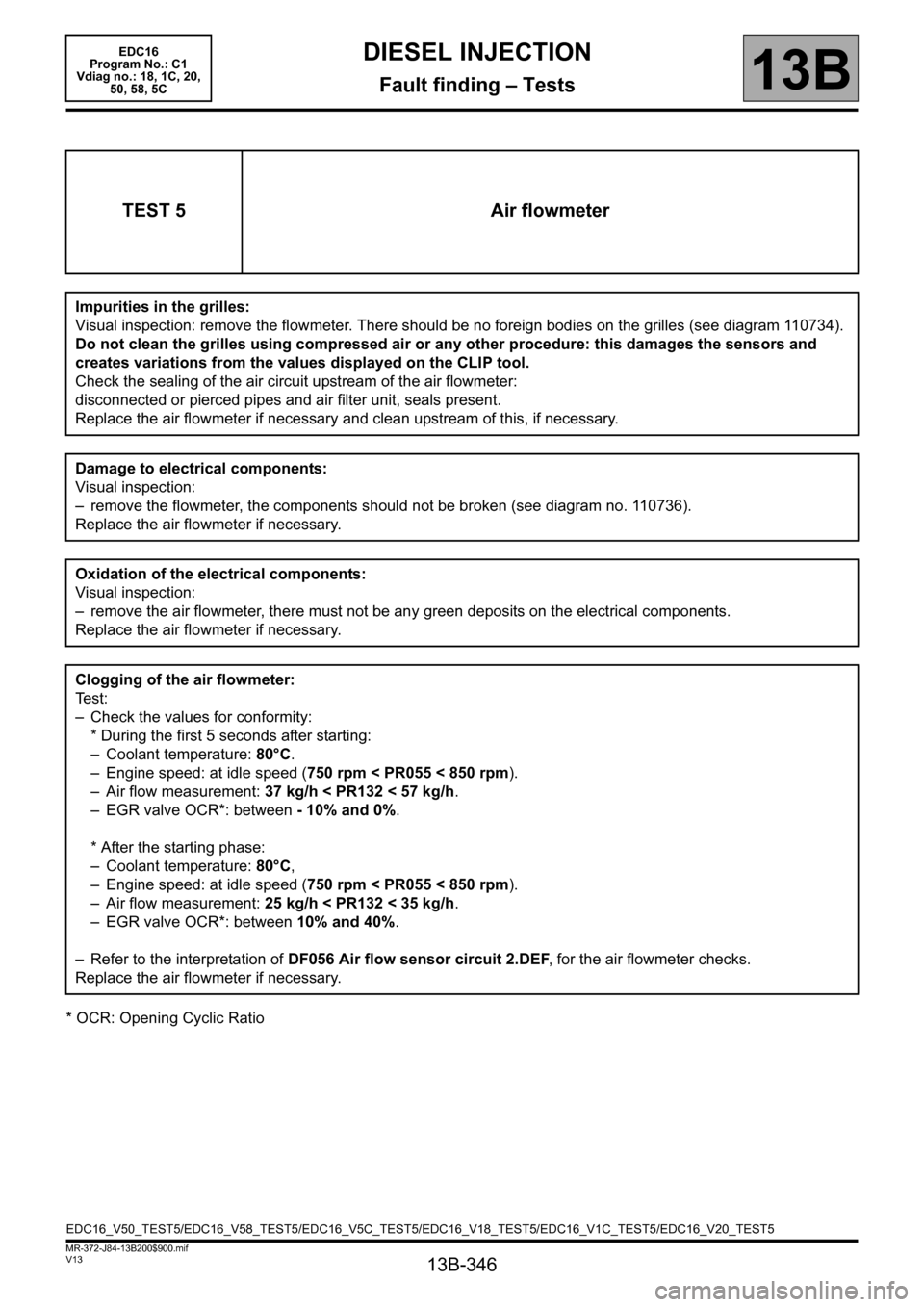
TEST 5 Air flowmeter
Impurities in the grilles:
Visual inspection: remove the flowmeter. There should be no foreign bodies on the grilles (see diagram 110734).
Do not clean the grilles using compressed air or any other procedure: this damages the sensors and
creates variations from the values displayed on the CLIP tool.
Check the sealing of the air circuit upstream of the air flowmeter:
disconnected or pierced pipes and air filter unit, seals present.
Replace the air flowmeter if necessary and clean upstream of this, if necessary.
Damage to electrical components:
Visual inspection:
– remove the flowmeter, the components should not be broken (see diagram no. 110736).
Replace the air flowmeter if necessary.
Oxidation of the electrical components:
Visual inspection:
– remove the air flowmeter, there must not be any green deposits on the electrical components.
Replace the air flowmeter if necessary.
Clogging of the air flowmeter:
Te s t :
– Check the values for conformity:
* During the first 5 seconds after starting:
– Coolant temperature: 80°C.
– Engine speed: at idle speed (750 rpm < PR055 < 850 rpm).
– Air flow measurement: 37 kg/h < PR132 < 57 kg/h.
– EGR valve OCR*: between - 10% and 0%.
* After the starting phase:
– Coolant temperature: 80°C,
– Engine speed: at idle speed (750 rpm < PR055 < 850 rpm).
– Air flow measurement: 25 kg/h < PR132 < 35 kg/h.
– EGR valve OCR*: between 10% and 40%.
– Refer to the interpretation of DF056 Air flow sensor circuit 2.DEF, for the air flowmeter checks.
Replace the air flowmeter if necessary.
EDC16_V50_TEST5/EDC16_V58_TEST5/EDC16_V5C_TEST5/EDC16_V18_TEST5/EDC16_V1C_TEST5/EDC16_V20_TEST5
Page 348 of 365
13B-348
MR-372-J84-13B200$900.mif
V13
EDC16
Program No.: C1
Vdiag no.: 18, 1C, 20,
50, 58, 5CDIESEL INJECTION
Fault finding – Tests13B
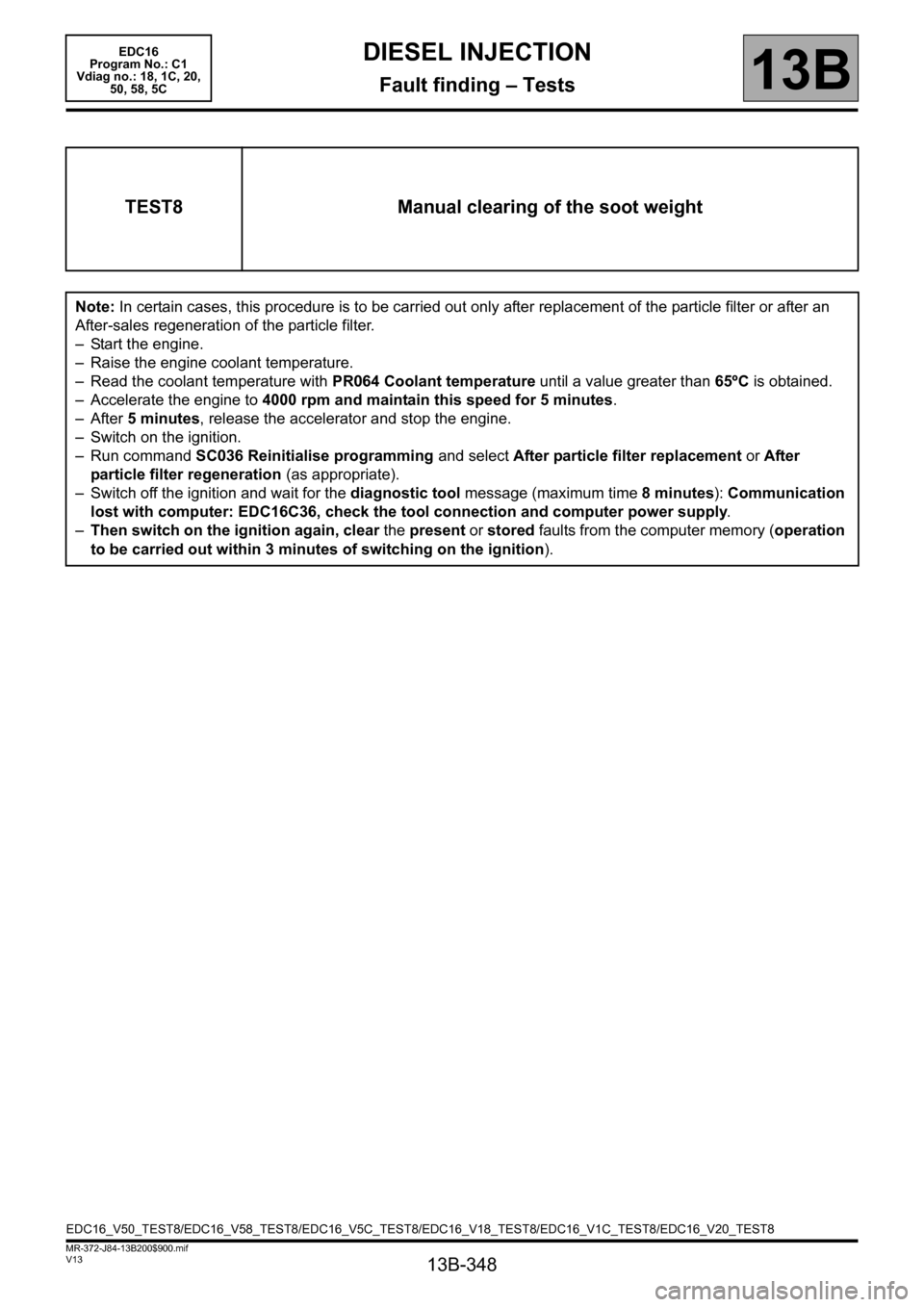
TEST8 Manual clearing of the soot weight
Note: In certain cases, this procedure is to be carried out only after replacement of the particle filter or after an
After-sales regeneration of the particle filter.
– Start the engine.
– Raise the engine coolant temperature.
– Read the coolant temperature with PR064 Coolant temperature until a value greater than 65ºC is obtained.
– Accelerate the engine to 4000 rpm and maintain this speed for 5 minutes.
–After 5 minutes, release the accelerator and stop the engine.
– Switch on the ignition.
– Run command SC036 Reinitialise programming and select After particle filter replacement or After
particle filter regeneration (as appropriate).
– Switch off the ignition and wait for the diagnostic tool message (maximum time 8 minutes): Communication
lost with computer: EDC16C36, check the tool connection and computer power supply.
–Then switch on the ignition again, clear the present or stored faults from the computer memory (operation
to be carried out within 3 minutes of switching on the ignition).
EDC16_V50_TEST8/EDC16_V58_TEST8/EDC16_V5C_TEST8/EDC16_V18_TEST8/EDC16_V1C_TEST8/EDC16_V20_TEST8
Page 350 of 365
13B-350
MR-372-J84-13B200$936.mif
V13
DIESEL INJECTION
Fault finding – Tests
EDC16
Program No: C1
Vdiag No: 18, 1C, 20,
50, 58, 5C
13B
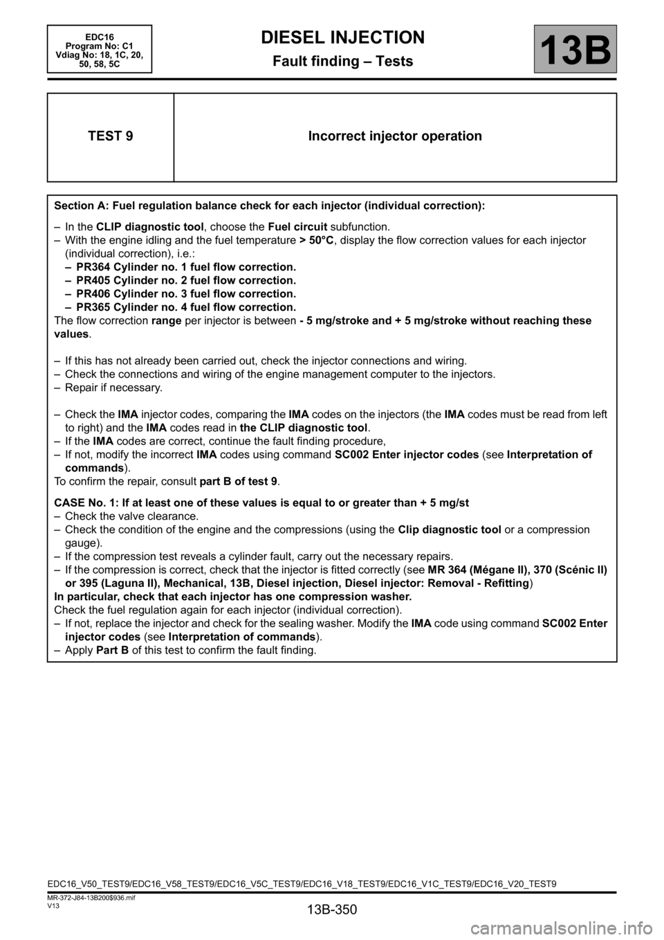
TEST 9 Incorrect injector operation
Section A: Fuel regulation balance check for each injector (individual correction):
– In the CLIP diagnostic tool, choose the Fuel circuit subfunction.
– With the engine idling and the fuel temperature > 50°C, display the flow correction values for each injector
(individual correction), i.e.:
– PR364 Cylinder no. 1 fuel flow correction.
– PR405 Cylinder no. 2 fuel flow correction.
– PR406 Cylinder no. 3 fuel flow correction.
– PR365 Cylinder no. 4 fuel flow correction.
The flow correction range per injector is between - 5 mg/stroke and + 5 mg/stroke without reaching these
values.
– If this has not already been carried out, check the injector connections and wiring.
– Check the connections and wiring of the engine management computer to the injectors.
– Repair if necessary.
– Check the IMA injector codes, comparing the IMA codes on the injectors (the IMA codes must be read from left
to right) and the IMA codes read in the CLIP diagnostic tool.
– If the IMA codes are correct, continue the fault finding procedure,
– If not, modify the incorrect IMA codes using command SC002 Enter injector codes (see Interpretation of
commands).
To confirm the repair, consult part B of test 9.
CASE No. 1: If at least one of these values is equal to or greater than + 5 mg/st
– Check the valve clearance.
– Check the condition of the engine and the compressions (using the Clip diagnostic tool or a compression
gauge).
– If the compression test reveals a cylinder fault, carry out the necessary repairs.
– If the compression is correct, check that the injector is fitted correctly (see MR 364 (Mégane II), 370 (Scénic II)
or 395 (Laguna II), Mechanical, 13B, Diesel injection, Diesel injector: Removal - Refitting)
In particular, check that each injector has one compression washer.
Check the fuel regulation again for each injector (individual correction).
– If not, replace the injector and check for the sealing washer. Modify the IMA code using command SC002 Enter
injector codes (see Interpretation of commands).
–Apply Part B of this test to confirm the fault finding.
EDC16_V50_TEST9/EDC16_V58_TEST9/EDC16_V5C_TEST9/EDC16_V18_TEST9/EDC16_V1C_TEST9/EDC16_V20_TEST9
Page 351 of 365
13B-351
MR-372-J84-13B200$936.mif
V13
DIESEL INJECTION
Fault finding – Tests
EDC16
Program No: C1
Vdiag No: 18, 1C, 20,
50, 58, 5C
13B
TEST 9
CONTINUED 1
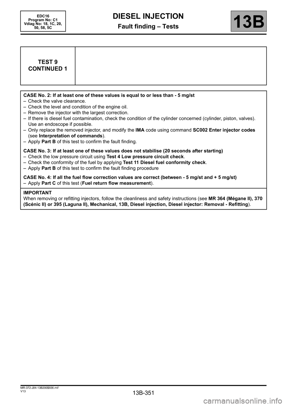
CASE No. 2: If at least one of these values is equal to or less than - 5 mg/st
– Check the valve clearance.
– Check the level and condition of the engine oil.
– Remove the injector with the largest correction.
– If there is diesel fuel contamination, check the condition of the cylinder concerned (cylinder, piston, valves).
Use an endoscope if possible.
– Only replace the removed injector, and modify the IMA code using command SC002 Enter injector codes
(see Interpretation of commands).
–Apply Part B of this test to confirm the fault finding.
CASE No. 3: If at least one of these values does not stabilise (20 seconds after starting)
– Check the low pressure circuit using Test 4 Low pressure circuit check.
– Check the conformity of the fuel by applying Test 11 Diesel fuel conformity check.
–Apply Part B of this test to confirm the fault finding procedure
CASE No. 4: If all the fuel flow correction values are correct (between - 5 mg/st and + 5 mg/st)
–Apply Part C of this test (Fuel return flow measurement).
IMPORTANT
When removing or refitting injectors, follow the cleanliness and safety instructions (see MR 364 (Mégane II), 370
(Scénic II) or 395 (Laguna II), Mechanical, 13B, Diesel injection, Diesel injector: Removal - Refitting).
Page 352 of 365

13B-352
MR-372-J84-13B200$936.mif
V13
DIESEL INJECTION
Fault finding – Tests
EDC16
Program No: C1
Vdiag No: 18, 1C, 20,
50, 58, 5C
13B
TEST 9
CONTINUED 2
Section B: Confirmation of flow correction fault finding for each injector (individual correction):
Clear the faults and perform a test with the engine idling for at least 5 minutes and fuel temperature > 50°C.
Check that no fault appears on the CLIP diagnostic tool and that the corrective values do not reach ±5mg/
stroke to confirm the repair.
If the customer complaint is still present and the fuel flow correction values are between
-5 mg/stroke and + 5mg/stroke, apply Part A Fuel regulation balance check for each injector (individual)
of this test (Case no.4).
If one or more cylinders has an injector flow correction value in excess of ± 5 mg/stroke, apply Part A Fuel
regulation balance check for each injector (individual) of this test, as one or more injectors may be defective.
Part C: Measuring fuel return flow
1 – Fitting the tool:
This section is only to be carried out if PR063 "Fuel temperature" is higher than 50°C (see step 2 of
section C for this test).
Remove the engine undertray
Disconnect the entire fuel return pipe in accordance with the following procedure (do not remove the clips):
– press the clip,
– pull vertically on the end piece (see arrow in the diagram below) of the fuel return pipe.
IMPORTANT
The end piece is fragile. Be careful not to break it by pulling it too hard. Replace all removed clips
Page 355 of 365
13B-355
MR-372-J84-13B200$936.mif
V13
EDC16
Program No: C1
Vdiag No: 18, 1C, 20,
50, 58, 5CDIESEL INJECTION
Fault finding – Tests13B
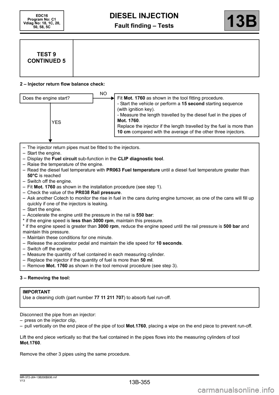
2 – Injector return flow balance check:
3 – Removing the tool:
Disconnect the pipe from an injector:
– press on the injector clip,
– pull vertically on the end piece of the pipe of tool Mot.1760, placing a wipe on the end piece to prevent run-off.
Lift the end piece vertically so that the fuel contained in the pipes flows into the measuring cylinders of tool
Mot.1760.
Remove the other 3 pipes using the same procedure.
TEST 9
CONTINUED 5
Does the engine start?
YES
– The injector return pipes must be fitted to the injectors.
– Start the engine.
– Display the Fuel circuit sub-function in the CLIP diagnostic tool.
– Raise the temperature of the engine.
– Read the diesel fuel temperature with PR063 Fuel temperature until a diesel fuel temperature greater than
50°C is reached
– Switch off the engine.
–Fit Mot. 1760 as shown in the installation procedure (see step 1).
– Check the value of the PR038 Rail pressure.
– Ask another Cotech to monitor the rise in fuel in the cans during engine turnover, as one of the cans will fill up
quickly if one of the injectors is leaking.
– Start the engine.
– Accelerate the engine until the pressure in the rail is 550 bar:
* if the engine speed is less than 3000 rpm, maintain this pressure.
* if the engine speed is greater than 3000 rpm, reduce the engine speed until the rail pressure is 500 bar and
maintain this pressure.
– Maintain these conditions for one minute.
– Release the accelerator pedal and maintain the idle speed for 10 seconds.
– Switch off the engine.
– Measure the quantity of fuel contained in each measuring cylinder.
– Replace the injector if the quantity of fuel is more than 50 ml.
– Remove Mot. 1760 as shown in the tool removal procedure (see step 3).
IMPORTANT
Use a cleaning cloth (part number 77 11 211 707) to absorb fuel run-off.NO
Fit Mot. 1760 as shown in the tool fitting procedure.
- Start the vehicle or perform a 15 second starting sequence
(with ignition key).
- Measure the length travelled by the diesel fuel in the pipes of
Mot. 1760.
Replace the injector if the length travelled by the fuel is more than
10 cm compared with the average of the other three injectors.
Page 357 of 365
13B-357
MR-372-J84-13B200$936.mif
V13
EDC16
Program No: C1
Vdiag No: 18, 1C, 20,
50, 58, 5CDIESEL INJECTION
Fault finding – Tests13B
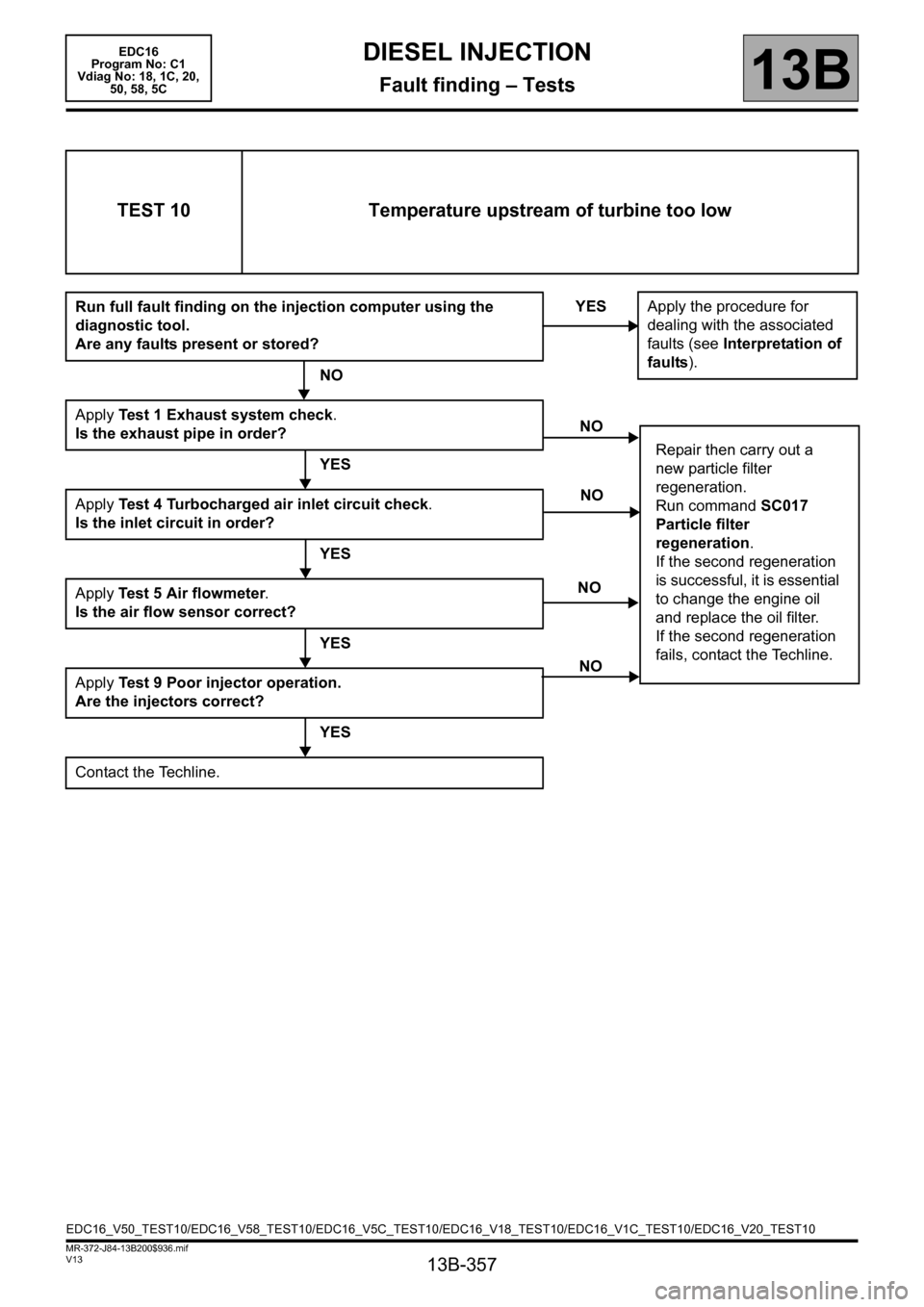
TEST 10 Temperature upstream of turbine too low
Run full fault finding on the injection computer using the
diagnostic tool.
Are any faults present or stored?
NO
Apply Test 1 Exhaust system check.
Is the exhaust pipe in order?
YES
Apply Test 4 Turbocharged air inlet circuit check.
Is the inlet circuit in order?
YES
Apply Test 5 Air flowmeter.
Is the air flow sensor correct?
YES
Apply Test 9 Poor injector operation.
Are the injectors correct?
YES
Contact the Techline.YES
Apply the procedure for
dealing with the associated
faults (see Interpretation of
faults).
NO
Repair then carry out a
new particle filter
regeneration.
Run command SC017
Particle filter
regeneration.
If the second regeneration
is successful, it is essential
to change the engine oil
and replace the oil filter.
If the second regeneration
fails, contact the Techline.
NO
NO
NO
EDC16_V50_TEST10/EDC16_V58_TEST10/EDC16_V5C_TEST10/EDC16_V18_TEST10/EDC16_V1C_TEST10/EDC16_V20_TEST10
Page 360 of 365
13B-360
MR-372-J84-13B200$936.mif
V13
DIESEL INJECTION
Fault finding – Tests
EDC16
Program No: C1
Vdiag No: 18, 1C, 20,
50, 58, 5C
13B
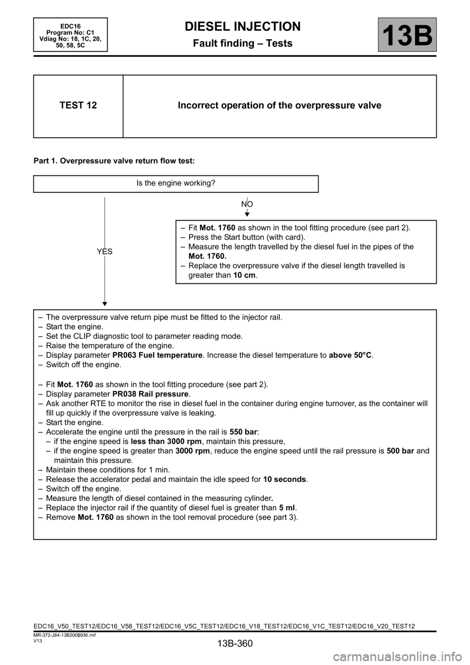
Part 1. Overpressure valve return flow test:
TEST 12 Incorrect operation of the overpressure valve
Is the engine working?
–Fit Mot. 1760 as shown in the tool fitting procedure (see part 2).
– Press the Start button (with card).
– Measure the length travelled by the diesel fuel in the pipes of the
Mot. 1760.
– Replace the overpressure valve if the diesel length travelled is
greater than 10 cm.
– The overpressure valve return pipe must be fitted to the injector rail.
– Start the engine.
– Set the CLIP diagnostic tool to parameter reading mode.
– Raise the temperature of the engine.
– Display parameter PR063 Fuel temperature. Increase the diesel temperature to above 50°C.
– Switch off the engine.
–Fit Mot. 1760 as shown in the tool fitting procedure (see part 2).
– Display parameter PR038 Rail pressure.
– Ask another RTE to monitor the rise in diesel fuel in the container during engine turnover, as the container will
fill up quickly if the overpressure valve is leaking.
– Start the engine.
– Accelerate the engine until the pressure in the rail is 550 bar:
– if the engine speed is less than 3000 rpm, maintain this pressure,
– if the engine speed is greater than 3000 rpm, reduce the engine speed until the rail pressure is 500 bar and
maintain this pressure.
– Maintain these conditions for 1 min.
– Release the accelerator pedal and maintain the idle speed for 10 seconds.
– Switch off the engine.
– Measure the length of diesel contained in the measuring cylinder.
– Replace the injector rail if the quantity of diesel fuel is greater than 5ml.
– Remove Mot. 1760 as shown in the tool removal procedure (see part 3).
YES
NO
EDC16_V50_TEST12/EDC16_V58_TEST12/EDC16_V5C_TEST12/EDC16_V18_TEST12/EDC16_V1C_TEST12/EDC16_V20_TEST12
Page 361 of 365
13B-361
MR-372-J84-13B200$936.mif
V13
DIESEL INJECTION
Fault finding – Tests
EDC16
Program No: C1
Vdiag No: 18, 1C, 20,
50, 58, 5C
13B
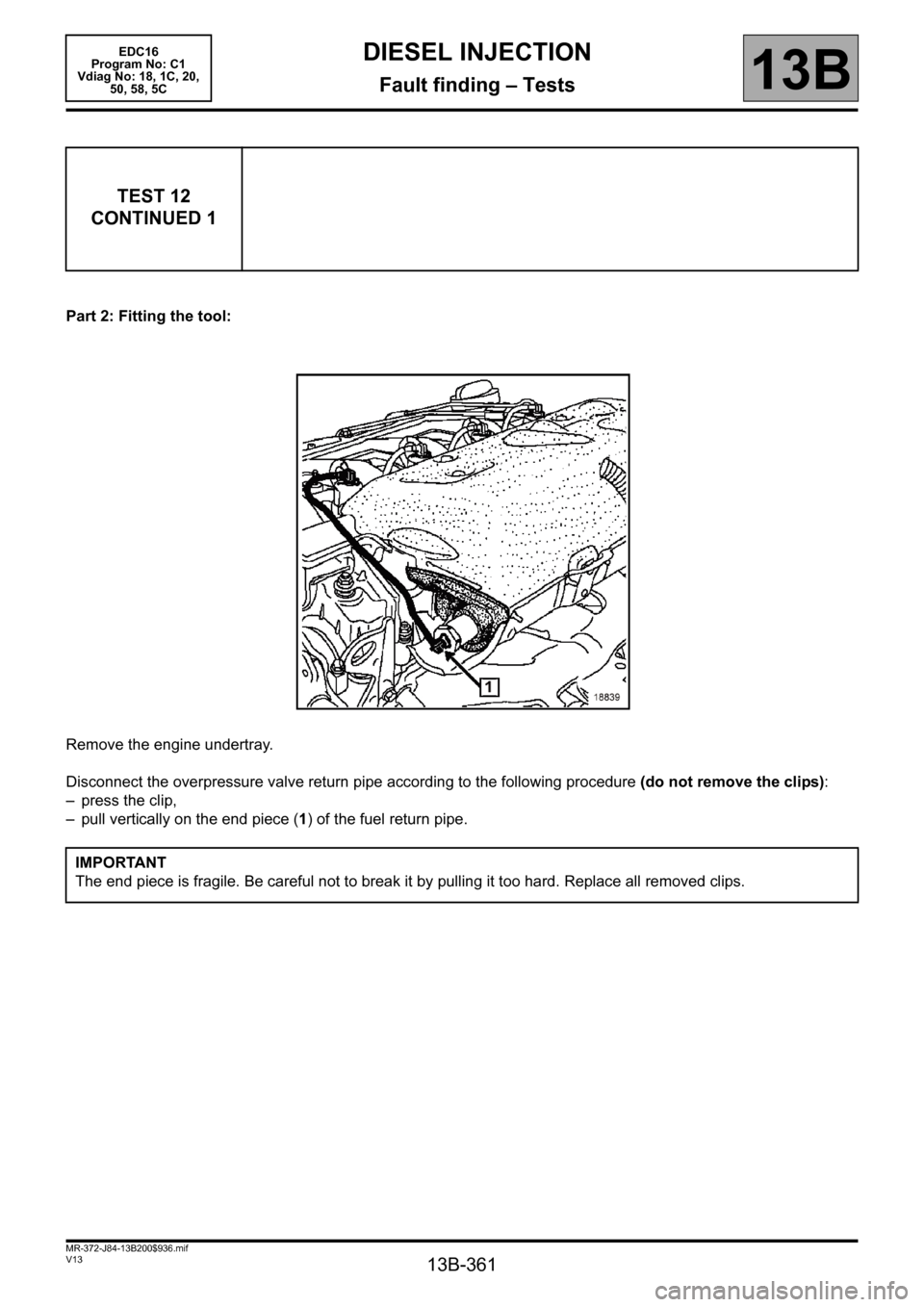
Part 2: Fitting the tool:
Remove the engine undertray.
Disconnect the overpressure valve return pipe according to the following procedure (do not remove the clips):
– press the clip,
– pull vertically on the end piece (1) of the fuel return pipe.
TEST 12
CONTINUED 1
IMPORTANT
The end piece is fragile. Be careful not to break it by pulling it too hard. Replace all removed clips.