ESP RENAULT SCENIC 2011 J95 / 3.G Engine And Peripherals EDC16 Owner's Manual
[x] Cancel search | Manufacturer: RENAULT, Model Year: 2011, Model line: SCENIC, Model: RENAULT SCENIC 2011 J95 / 3.GPages: 365, PDF Size: 2.11 MB
Page 168 of 365
13B-168
MR-372-J84-13B200$504.mif
V13
EDC16
Program No: C1
Vdiag No: 18, 1C, 20,
50, 58, 5CDIESEL INJECTION
Fault finding – Interpretation of statuses13B
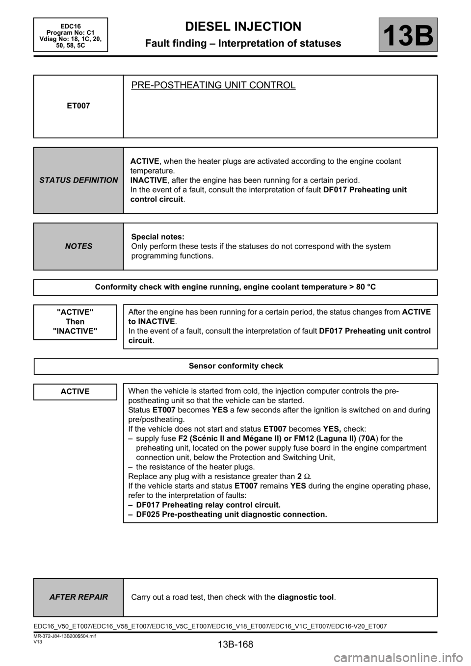
ET007
PRE-POSTHEATING UNIT CONTROL
STATUS DEFINITIONACTIVE, when the heater plugs are activated according to the engine coolant
temperature.
INACTIVE, after the engine has been running for a certain period.
In the event of a fault, consult the interpretation of fault DF017 Preheating unit
control circuit.
NOTESSpecial notes:
Only perform these tests if the statuses do not correspond with the system
programming functions.
Conformity check with engine running, engine coolant temperature > 80 °C
"ACTIVE"
Then
"INACTIVE"
After the engine has been running for a certain period, the status changes from ACTIVE
to INACTIVE.
In the event of a fault, consult the interpretation of fault DF017 Preheating unit control
circuit.
Sensor conformity check
ACTIVEWhen the vehicle is started from cold, the injection computer controls the pre-
postheating unit so that the vehicle can be started.
Status ET007 becomes YES a few seconds after the ignition is switched on and during
pre/postheating.
If the vehicle does not start and status ET007 becomes YES, check:
– supply fuse F2 (Scénic II and Mégane II) or FM12 (Laguna II) (70A) for the
preheating unit, located on the power supply fuse board in the engine compartment
connection unit, below the Protection and Switching Unit,
– the resistance of the heater plugs.
Replace any plug with a resistance greater than 2Ω.
If the vehicle starts and status ET007 remains YES during the engine operating phase,
refer to the interpretation of faults:
– DF017 Preheating relay control circuit.
– DF025 Pre-postheating unit diagnostic connection.
AFTER REPAIRCarry out a road test, then check with the diagnostic tool.
EDC16_V50_ET007/EDC16_V58_ET007/EDC16_V5C_ET007/EDC16_V18_ET007/EDC16_V1C_ET007/EDC16-V20_ET007
Page 170 of 365
13B-170
MR-372-J84-13B200$504.mif
V13
EDC16
Program No: C1
Vdiag No: 18, 1C, 20,
50, 58, 5CDIESEL INJECTION
Fault finding – Interpretation of statuses13B
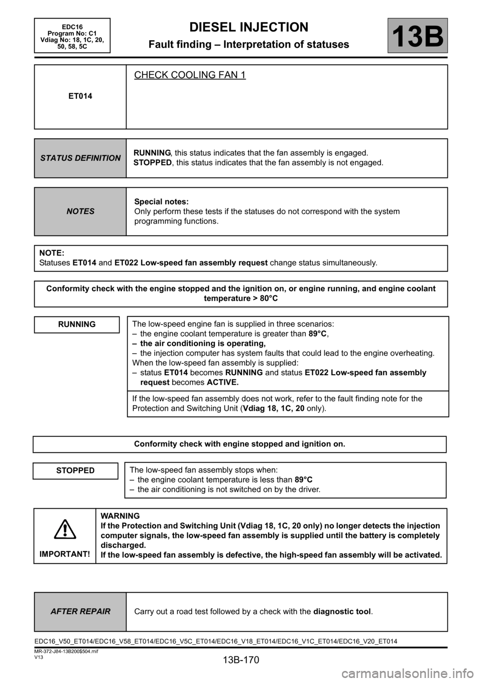
ET014
CHECK COOLING FAN 1
STATUS DEFINITIONRUNNING, this status indicates that the fan assembly is engaged.
STOPPED, this status indicates that the fan assembly is not engaged.
NOTESSpecial notes:
Only perform these tests if the statuses do not correspond with the system
programming functions.
NOTE:
Statuses ET014 and ET022 Low-speed fan assembly request change status simultaneously.
Conformity check with the engine stopped and the ignition on, or engine running, and engine coolant
temperature > 80°C
RUNNING
The low-speed engine fan is supplied in three scenarios:
– the engine coolant temperature is greater than 89°C,
– the air conditioning is operating,
– the injection computer has system faults that could lead to the engine overheating.
When the low-speed fan assembly is supplied:
–status ET014 becomes RUNNING and status ET022 Low-speed fan assembly
request becomes ACTIVE.
If the low-speed fan assembly does not work, refer to the fault finding note for the
Protection and Switching Unit (Vdiag 18, 1C, 20 only).
Conformity check with engine stopped and ignition on.
STOPPEDThe low-speed fan assembly stops when:
– the engine coolant temperature is less than 89°C
– the air conditioning is not switched on by the driver.
IMPORTANT!WARNING
If the Protection and Switching Unit (Vdiag 18, 1C, 20 only) no longer detects the injection
computer signals, the low-speed fan assembly is supplied until the battery is completely
discharged.
If the low-speed fan assembly is defective, the high-speed fan assembly will be activated.
AFTER REPAIRCarry out a road test followed by a check with the diagnostic tool.
EDC16_V50_ET014/EDC16_V58_ET014/EDC16_V5C_ET014/EDC16_V18_ET014/EDC16_V1C_ET014/EDC16_V20_ET014
Page 171 of 365
13B-171
MR-372-J84-13B200$504.mif
V13
EDC16
Program No: C1
Vdiag No: 18, 1C, 20,
50, 58, 5CDIESEL INJECTION
Fault finding – Interpretation of statuses13B
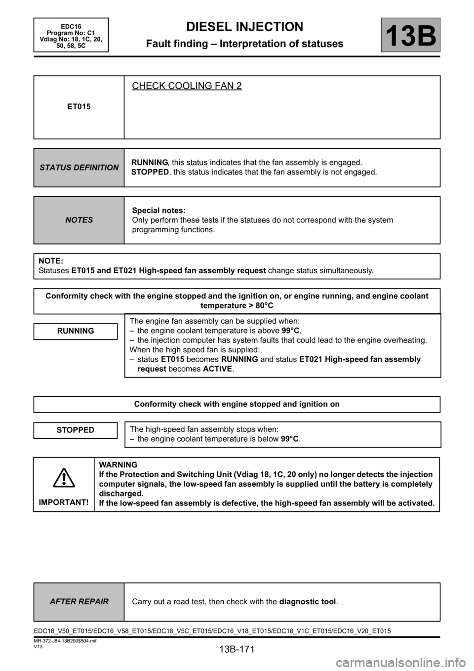
ET015
CHECK COOLING FAN 2
STATUS DEFINITIONRUNNING, this status indicates that the fan assembly is engaged.
STOPPED, this status indicates that the fan assembly is not engaged.
NOTESSpecial notes:
Only perform these tests if the statuses do not correspond with the system
programming functions.
NOTE:
Statuses ET015 and ET021 High-speed fan assembly request change status simultaneously.
Conformity check with the engine stopped and the ignition on, or engine running, and engine coolant
temperature > 80°C
RUNNING
The engine fan assembly can be supplied when:
– the engine coolant temperature is above 99°C,
– the injection computer has system faults that could lead to the engine overheating.
When the high speed fan is supplied:
–status ET015 becomes RUNNING and status ET021 High-speed fan assembly
request becomes ACTIVE.
Conformity check with engine stopped and ignition on
STOPPEDThe high-speed fan assembly stops when:
– the engine coolant temperature is below 99°C.
IMPORTANT!WARNING
If the Protection and Switching Unit (Vdiag 18, 1C, 20 only) no longer detects the injection
computer signals, the low-speed fan assembly is supplied until the battery is completely
discharged.
If the low-speed fan assembly is defective, the high-speed fan assembly will be activated.
AFTER REPAIRCarry out a road test, then check with the diagnostic tool.
EDC16_V50_ET015/EDC16_V58_ET015/EDC16_V5C_ET015/EDC16_V18_ET015/EDC16_V1C_ET015/EDC16_V20_ET015
Page 172 of 365
13B-172
MR-372-J84-13B200$504.mif
V13
EDC16
Program No: C1
Vdiag No: 18, 1C, 20,
50, 58, 5CDIESEL INJECTION
Fault finding – Interpretation of statuses13B
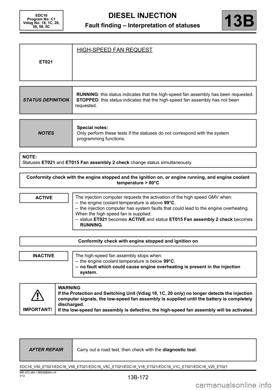
ET021
HIGH-SPEED FAN REQUEST
STATUS DEFINITIONRUNNING: this status indicates that the high-speed fan assembly has been requested.
STOPPED: this status indicates that the high-speed fan assembly has not been
requested.
NOTESSpecial notes:
Only perform these tests if the statuses do not correspond with the system
programming functions.
NOTE:
Statuses ET021 and ET015 Fan assembly 2 check change status simultaneously.
Conformity check with the engine stopped and the ignition on, or engine running, and engine coolant
temperature > 80°C
ACTIVE
The injection computer requests the activation of the high speed GMV when:
– the engine coolant temperature is above 99°C.
– the injection computer has system faults that could lead to the engine overheating.
When the high speed fan is supplied:
–status ET021 becomes ACTIVE and status ET015 Fan assembly 2 check becomes
RUNNING.
Conformity check with engine stopped and ignition on
INACTIVEThe high-speed fan assembly stops when:
– the engine coolant temperature is below 99°C,
– no fault which could cause engine overheating is present in the injection
system.
IMPORTANT!WA R N I N G
If the Protection and Switching Unit (Vdiag 18, 1C, 20 only) no longer detects the injection
computer signals, the low-speed fan assembly is supplied until the battery is completely
discharged.
If the low-speed fan assembly is defective, the high-speed fan assembly will be activated.
AFTER REPAIRCarry out a road test, then check with the diagnostic tool.
EDC16_V50_ET021/EDC16_V58_ET021/EDC16_V5C_ET021/EDC16_V18_ET021/EDC16_V1C_ET021/EDC16_V20_ET021
Page 173 of 365
13B-173
MR-372-J84-13B200$504.mif
V13
EDC16
Program No: C1
Vdiag No: 18, 1C, 20,
50, 58, 5CDIESEL INJECTION
Fault finding – Interpretation of statuses13B
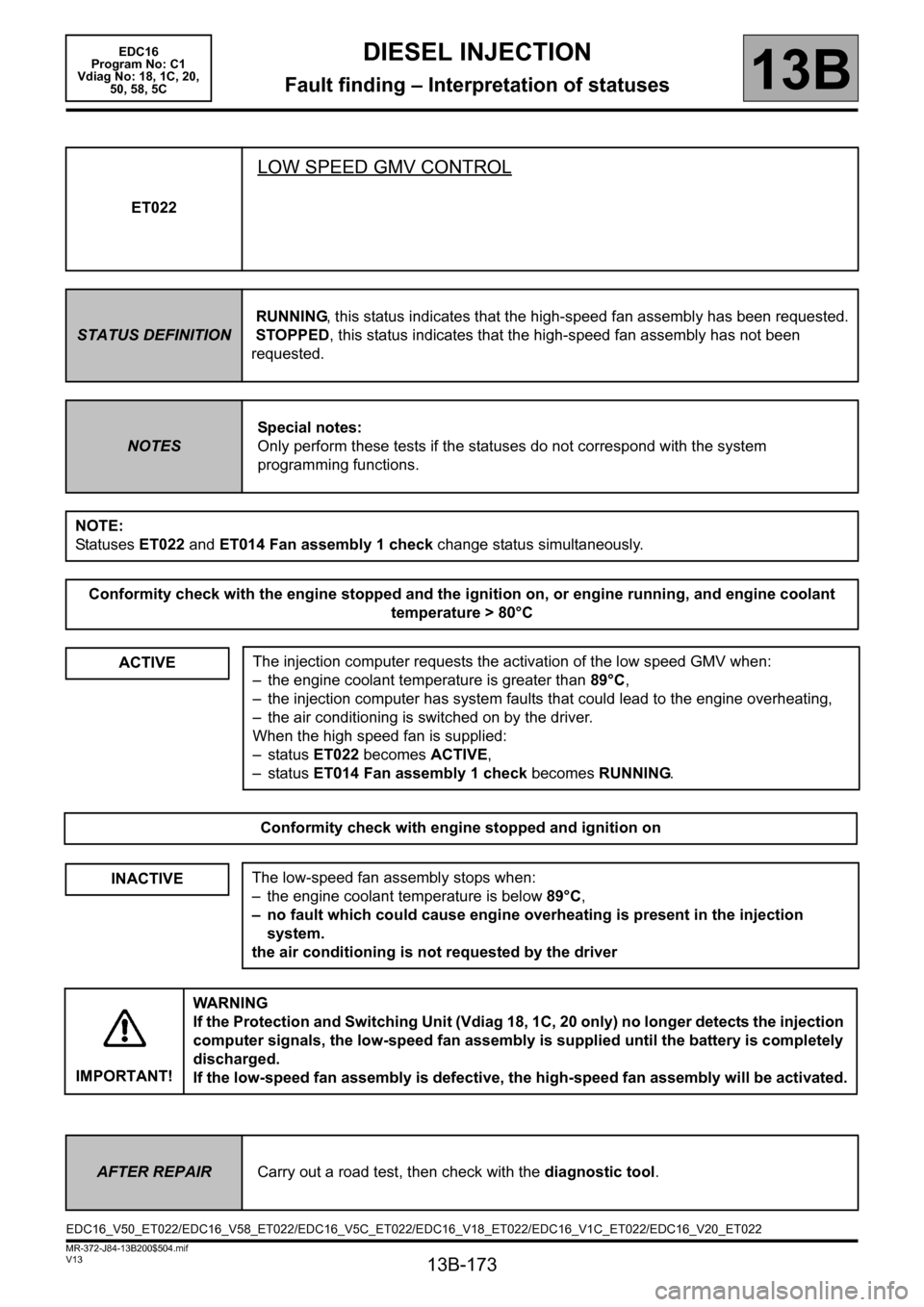
ET022
LOW SPEED GMV CONTROL
STATUS DEFINITIONRUNNING, this status indicates that the high-speed fan assembly has been requested.
STOPPED, this status indicates that the high-speed fan assembly has not been
requested.
NOTESSpecial notes:
Only perform these tests if the statuses do not correspond with the system
programming functions.
NOTE:
Statuses ET022 and ET014 Fan assembly 1 check change status simultaneously.
Conformity check with the engine stopped and the ignition on, or engine running, and engine coolant
temperature > 80°C
ACTIVE
The injection computer requests the activation of the low speed GMV when:
– the engine coolant temperature is greater than 89°C,
– the injection computer has system faults that could lead to the engine overheating,
– the air conditioning is switched on by the driver.
When the high speed fan is supplied:
–status ET022 becomes ACTIVE,
–status ET014 Fan assembly 1 check becomes RUNNING.
Conformity check with engine stopped and ignition on
INACTIVEThe low-speed fan assembly stops when:
– the engine coolant temperature is below 89°C,
– no fault which could cause engine overheating is present in the injection
system.
the air conditioning is not requested by the driver
IMPORTANT!WARNING
If the Protection and Switching Unit (Vdiag 18, 1C, 20 only) no longer detects the injection
computer signals, the low-speed fan assembly is supplied until the battery is completely
discharged.
If the low-speed fan assembly is defective, the high-speed fan assembly will be activated.
AFTER REPAIRCarry out a road test, then check with the diagnostic tool.
EDC16_V50_ET022/EDC16_V58_ET022/EDC16_V5C_ET022/EDC16_V18_ET022/EDC16_V1C_ET022/EDC16_V20_ET022
Page 174 of 365
13B-174
MR-372-J84-13B200$504.mif
V13
EDC16
Program No: C1
Vdiag No: 18, 1C, 20,
50, 58, 5CDIESEL INJECTION
Fault finding – Interpretation of statuses13B
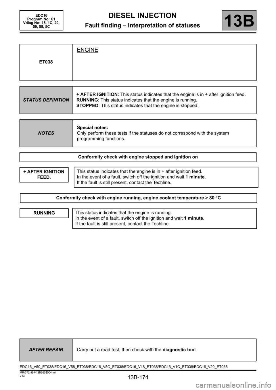
ET038
ENGINE
STATUS DEFINITION+ AFTER IGNITION: This status indicates that the engine is in + after ignition feed.
RUNNING: This status indicates that the engine is running.
STOPPED: This status indicates that the engine is stopped.
NOTESSpecial notes:
Only perform these tests if the statuses do not correspond with the system
programming functions.
Conformity check with engine stopped and ignition on
+ AFTER IGNITION
FEED.
This status indicates that the engine is in + after ignition feed.
In the event of a fault, switch off the ignition and wait 1 minute.
If the fault is still present, contact the Techline.
Conformity check with engine running, engine coolant temperature > 80 °C
RUNNINGThis status indicates that the engine is running.
In the event of a fault, switch off the ignition and wait 1 minute.
If the fault is still present, contact the Techline.
AFTER REPAIRCarry out a road test, then check with the diagnostic tool.
EDC16_V50_ET038/EDC16_V58_ET038/EDC16_V5C_ET038/EDC16_V18_ET038/EDC16_V1C_ET038/EDC16_V20_ET038
Page 175 of 365
13B-175
MR-372-J84-13B200$504.mif
V13
EDC16
Program No: C1
Vdiag No: 18, 1C, 20,
50, 58, 5CDIESEL INJECTION
Fault finding – Interpretation of statuses13B
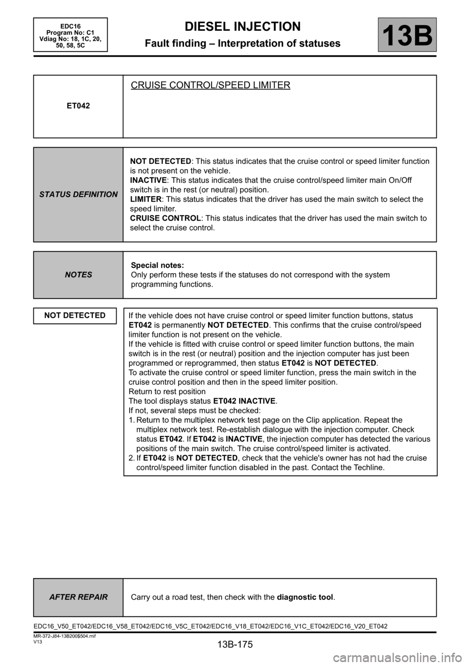
ET042
CRUISE CONTROL/SPEED LIMITER
STATUS DEFINITIONNOT DETECTED: This status indicates that the cruise control or speed limiter function
is not present on the vehicle.
INACTIVE: This status indicates that the cruise control/speed limiter main On/Off
switch is in the rest (or neutral) position.
LIMITER: This status indicates that the driver has used the main switch to select the
speed limiter.
CRUISE CONTROL: This status indicates that the driver has used the main switch to
select the cruise control.
NOTESSpecial notes:
Only perform these tests if the statuses do not correspond with the system
programming functions.
NOT DETECTED
If the vehicle does not have cruise control or speed limiter function buttons, status
ET042 is permanently NOT DETECTED. This confirms that the cruise control/speed
limiter function is not present on the vehicle.
If the vehicle is fitted with cruise control or speed limiter function buttons, the main
switch is in the rest (or neutral) position and the injection computer has just been
programmed or reprogrammed, then status ET042 is NOT DETECTED.
To activate the cruise control or speed limiter function, press the main switch in the
cruise control position and then in the speed limiter position.
Return to rest position
The tool displays status ET042 INACTIVE.
If not, several steps must be checked:
1. Return to the multiplex network test page on the Clip application. Repeat the
multiplex network test. Re-establish dialogue with the injection computer. Check
status ET042. If ET042 is INACTIVE, the injection computer has detected the various
positions of the main switch. The cruise control/speed limiter is activated.
2. If ET042 is NOT DETECTED, check that the vehicle's owner has not had the cruise
control/speed limiter function disabled in the past. Contact the Techline.
AFTER REPAIRCarry out a road test, then check with the diagnostic tool.
EDC16_V50_ET042/EDC16_V58_ET042/EDC16_V5C_ET042/EDC16_V18_ET042/EDC16_V1C_ET042/EDC16_V20_ET042
Page 176 of 365

13B-176
MR-372-J84-13B200$504.mif
V13
EDC16
Program No: C1
Vdiag No: 18, 1C, 20,
50, 58, 5CDIESEL INJECTION
Fault finding – Interpretation of statuses13B
ET042
CONTINUED 1
INACTIVE
Procedure to apply for Laguna II:
When the main switch is in rest position (or neutral), status ET042 is INACTIVE.
If CRUISE CONTROL or SPEED LIMITER appears despite the main switch being in
the rest (or neutral) position, carry out the following operations:
Check the connections of the cruise control/speed limiter main switch.
Check for + 12 V APC on the main switch connector.
– Connection code AP10 of component 1081.
Disconnect the main switch and with it in the rest position, check the insulation
between:
– Connection codes AP10 and 3FX of component 1081.
– Connection codes AP10 and 3PD of component 1081.
Check the continuity between connections AP10 and 3PD of component 1081 in the
speed limiter position.
Check the continuity between connections AP10 and 3FX of component 1081 in the
cruise control position.
If these checks are not in order, replace the switch.
Check the insulation, continuity and the absence of interference resistance on the
following connections:
– Connection code 3FX,
– Connection code3PD.
Between components 1081 and 120.
Also check the engine management computer connectors.
If there is a repair method (see Technical Note 6015A, Repairing electrical wiring,
Wiring: Precautions for repair), repair the wiring, otherwise replace it.
AFTER REPAIRCarry out a road test followed by a check with the diagnostic tool.
Page 177 of 365

13B-177
MR-372-J84-13B200$504.mif
V13
EDC16
Program No: C1
Vdiag No: 18, 1C, 20,
50, 58, 5CDIESEL INJECTION
Fault finding – Interpretation of statuses13B
ET042
CONTINUED 2
INACTIVE
Procedure to apply for Mégane II and Scénic II:
When the main switch is in rest position (or neutral), status ET042 is INACTIVE.
If CRUISE CONTROL or SPEED LIMITER appears despite the main switch being in
the rest (or neutral) position, carry out the following operations:
Check the connections of the cruise control/speed limiter main switch.
Check for + 12 V APC on the main switch connector.
– Connection code AP43 of component 1081 (Mégane II)
– Connection code AP43 of component 1546 (Scénic II)
Disconnect the main switch and with it in the rest position, check the insulation
between:
– Connection codes AP43 and 3FX of component 1081 (Mégane II)
– Connection codes AP43 and 3PD of component 1081 (Mégane II)
– Connection codes AP43 and 3FX of component 1546 (Scénic II)
– Connection codes AP43 and 3PD of component 1546 (Scénic II)
Check the continuity between connections AP43 and 3PD of component 1081
(Mégane II) and component 1546 (Scénic II) in the speed limiter position.
Check the continuity between connections AP43 and 3FX of component 1081
(Mégane II) and component 1546 (Scénic II) in the cruise control position.
If these checks are not in order, replace the switch.
Check the continuity, insulation and the absence of interference resistance on the
following connections:
– Connection code 3FX,
– Connection code3PD.
Between components 1081 and 120 (Mégane II)
Between components 1546 and 120 (Scénic II)
Also check the engine management computer connectors.
If there is a repair method (see Technical Note 6015A, Repairing electrical wiring,
Wiring: Precautions for repair), repair the wiring, otherwise replace it.
AFTER REPAIRCarry out a road test followed by a check with the diagnostic tool.
Page 182 of 365
13B-182
MR-372-J84-13B200$504.mif
V13
EDC16
Program No: C1
Vdiag No: 18, 1C, 20,
50, 58, 5CDIESEL INJECTION
Fault finding – Interpretation of statuses13B
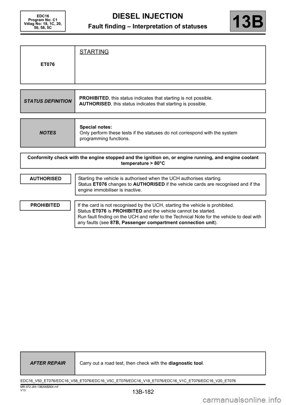
ET076
STARTING
STATUS DEFINITIONPROHIBITED, this status indicates that starting is not possible.
AUTHORISED, this status indicates that starting is possible.
NOTESSpecial notes:
Only perform these tests if the statuses do not correspond with the system
programming functions.
Conformity check with the engine stopped and the ignition on, or engine running, and engine coolant
temperature > 80°C
AUTHORISED
Starting the vehicle is authorised when the UCH authorises starting.
Status ET076 changes to AUTHORISED if the vehicle cards are recognised and if the
engine immobiliser is inactive.
PROHIBITEDIf the card is not recognised by the UCH, starting the vehicle is prohibited.
Status ET076 is PROHIBITED and the vehicle cannot be started.
Run fault finding on the UCH and refer to the Technical Note for the vehicle to deal with
any faults (see87B, Passenger compartment connection unit).
AFTER REPAIRCarry out a road test, then check with the diagnostic tool.
EDC16_V50_ET076/EDC16_V58_ET076/EDC16_V5C_ET076/EDC16_V18_ET076/EDC16_V1C_ET076/EDC16_V20_ET076