light RENAULT SCENIC 2011 J95 / 3.G Engine And Peripherals EDC16 Owner's Manual
[x] Cancel search | Manufacturer: RENAULT, Model Year: 2011, Model line: SCENIC, Model: RENAULT SCENIC 2011 J95 / 3.GPages: 365, PDF Size: 2.11 MB
Page 40 of 365
13B-40
MR-372-J84-13B200$252.mif
V13
DIESEL INJECTION
Fault finding – Interpretation of faults
EDC16
Program No.: C1
Vdiag no.: 18, 1C, 20,
50, 58, 5C
13B
DF008
PRESENT
OR
STOREDPEDAL POTENTIOMETER CIRCUIT GANG 1
CO.0: Open circuit or short circuit to earth
CC.1 : Short circuit to + 12 V
1.DEF: Inconsistent signal
2.DEF: Accelerator pedal sensor locked
NOTESConditions for applying the fault finding procedure to stored faults:
The fault is declared present after a series of full-load/no-load actions on the
accelerator pedal.
Special notes:
Turbocharging, passenger compartment heating resistor activation and the cruise
control/speed limiter are not authorised.
If CO.0, CC.1 or 1.DEF is present the level 1 warning light is lit.
The engine speed is fixed at 1400 rpm if there is a fault on gangs 1 and 2 of the pedal
potentiometer and the engine torque is limited.
Use bornier Elé. 1681 or Elé. 1590 for all operations on the computer connectors.
Priorities when dealing with a number of faults:
Deal with fault first if it is DF011 Sensor feed voltage no. 1 first if it is present or
stored.
WARNING
This fault may appear if the wiring harness has been damaged.
Follow the procedure described in the Wiring Check in the Introduction.
This check enables the condition and the conformity of the engine wiring harness to be checked.
CO.0
NOTESPriorities when dealing with a number of faults:
If fault DF009 Pedal potentiometer circuit gang 2 is
present at the same time, check that the pedal sensor
connector is connected correctly.
Check the pedal potentiometer connections.
Check the injection computer connections.
Repair if necessary.
Check the continuity and insulation to earth of the following connections:
– connection code 3KW,
– connection code 3LR,
between components 120 and 921.
If the connection or connections are faulty and there is a repair method (see Technical Note 6015A, Repairing
electrical wiring, Wiring: Precautions for repair), repair the wiring, otherwise replace it.
Measure the resistance of the pedal potentiometer on gang 1 between connections 3LR and 3LT.
Replace the pedal potentiometer if the resistance is not approximately 0.8 kΩ < X < 2.6 kΩ.
AFTER REPAIRDeal with any faults.
Carry out a road test followed by another check with the diagnostic tool.
EDC16_V50_DF008/EDC16_V58_DF008/EDC16_V5C_DF008/EDC16_V18_DF008/EDC16_V1C_DF008/EDC16_V20_DF008
Page 42 of 365
13B-42
MR-372-J84-13B200$252.mif
V13
DIESEL INJECTION
Fault finding – Interpretation of faults
EDC16
Program No.: C1
Vdiag no.: 18, 1C, 20,
50, 58, 5C
13B
DF008
CONTINUED 2
1.DEF
NOTESNone
Check the pedal potentiometer connections.
Check the injection computer connections.
Repair if necessary.
Check the continuity and absence of interference resistance of the following connections:
– connection code 3LS,
– connection code 3LR,
– connection code 3LT,
– connection code3LW,
– connection code 3LU,
– connection code 3LV.
between components 120 and 921.
If the connection or connections are faulty and there is a repair method (see Technical Note 6015A, Repairing
electrical wiring, Wiring: Precautions for repair), repair the wiring, otherwise replace it.
If the fault is still present, replace the pedal potentiometer.
2.DEF
NOTESNone
Check the mechanical condition of the accelerator pedal:
– locked in full load position,
– with the pedal blocked by an external component.
Repair if necessary.
Check the brake light switch.
Vary the position of the pedal and refer to the conformity check in order to check the operating values of the
accelerator pedal potentiometer.
If the values displayed are inconsistent, replace the accelerator pedal potentiometer.
AFTER REPAIRDeal with any faults.
Carry out a road test followed by another check with the diagnostic tool.
Page 43 of 365
13B-43
MR-372-J84-13B200$252.mif
V13
DIESEL INJECTION
Fault finding – Interpretation of faults
EDC16
Program No.: C1
Vdiag no.: 18, 1C, 20,
50, 58, 5C
13B
DF009
PRESENT
OR
STOREDPEDAL POTENTIOMETER CIRCUIT GANG 2
CO.0: Open circuit or short circuit to earth
CC.1 : Short circuit to + 12 V
1.DEF: Inconsistent signal
NOTESConditions for applying the fault finding procedure to stored faults:
The fault is declared present after a series of full-load/no-load actions on the
accelerator pedal.
Special notes:
Turbocharging, passenger compartment heating resistor activation and the cruise
control/speed limiter are not authorised.
If the fault is present, the level 1 warning light is lit.
The engine speed is fixed at 1400 rpm if there is a fault on gangs 1 and 2 of the pedal
potentiometer and the engine torque is limited.
Use bornier Ele. 1681 or Ele. 1590 for all operations on the computer connectors.
Priorities when dealing with a number of faults:
Deal with fault DF012 Sensor supply voltage no. 2 first if it is present or stored.
WARNING
This fault may appear if the wiring harness has been damaged.
Follow the procedure described in the Wiring Check in the Introduction.
This check enables the condition and the conformity of the engine wiring harness to be checked.
AFTER REPAIRDeal with any faults.
Carry out a road test followed by another check with the diagnostic tool.
EDC16_V50_DF009/EDC16_V58_DF009/EDC16_V5C_DF009/EDC16_V18_DF009/EDC16_V1C_DF009/EDC16_V20_DF009
Page 47 of 365
13B-47
MR-372-J84-13B200$252.mif
V13
DIESEL INJECTION
Fault finding – Interpretation of faults
EDC16
Program No.: C1
Vdiag no.: 18, 1C, 20,
50, 58, 5C
13B
DF011
PRESENT
OR
STOREDSENSOR SUPPLY VOLTAGE NO. 1
1.DEF: Sensor reference voltage too low
2.DEF: Sensor reference voltage too high
NOTESConditions for applying the fault finding procedure to stored faults:
The fault is declared present after carrying out a road test or after several attempts at
starting the engine.
Special notes:
If the fault is present:
– the cruise control/speed limiter function is inhibited,
– turbocharging is inhibited,
– the engine speed is limited,
– the level 1 warning light is lit,
– the OBD warning light illuminates after three consecutive driving cycles (start the
engine
+ 5 seconds, then switch off the ignition and wait for 1 minute).
Use bornier Elé.1681 or Elé.1590 for any operation on the injection computer
connectors.
WARNING
This fault may appear if the wiring harness has been damaged.
Follow the procedure described in the Wiring Check in the Introduction.
This check enables the condition and the conformity of the engine wiring harness to be checked.
AFTER REPAIRDeal with any faults.
Carry out a road test followed by another check with the diagnostic tool.
EDC16_V50_DF011/EDC16_V58_DF011/EDC16_V5C_DF011/EDC16_V18_DF011/EDC16_V1C_DF011/EDC16_V20_DF011
Page 50 of 365
13B-50
MR-372-J84-13B200$252.mif
V13
DIESEL INJECTION
Fault finding – Interpretation of faults
EDC16
Program No.: C1
Vdiag no.: 18, 1C, 20,
50, 58, 5C
13B
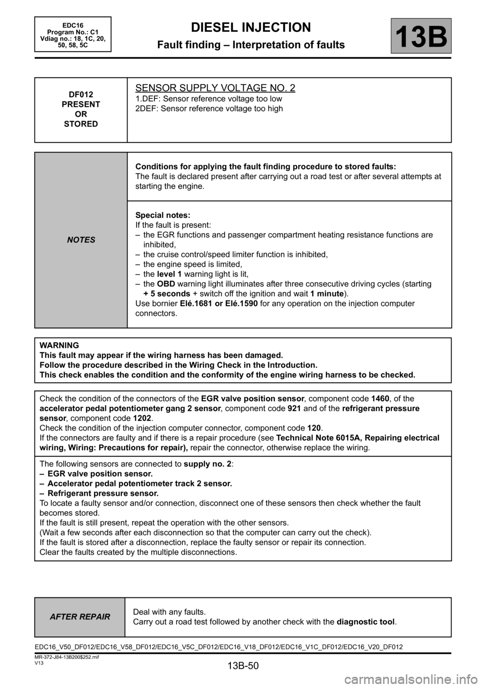
DF012
PRESENT
OR
STOREDSENSOR SUPPLY VOLTAGE NO. 2
1.DEF: Sensor reference voltage too low
2DEF: Sensor reference voltage too high
NOTESConditions for applying the fault finding procedure to stored faults:
The fault is declared present after carrying out a road test or after several attempts at
starting the engine.
Special notes:
If the fault is present:
– the EGR functions and passenger compartment heating resistance functions are
inhibited,
– the cruise control/speed limiter function is inhibited,
– the engine speed is limited,
– the level 1 warning light is lit,
– the OBD warning light illuminates after three consecutive driving cycles (starting
+ 5 seconds + switch off the ignition and wait 1 minute).
Use bornier Elé.1681 or Elé.1590 for any operation on the injection computer
connectors.
WARNING
This fault may appear if the wiring harness has been damaged.
Follow the procedure described in the Wiring Check in the Introduction.
This check enables the condition and the conformity of the engine wiring harness to be checked.
Check the condition of the connectors of the EGR valve position sensor, component code 1460, of the
accelerator pedal potentiometer gang 2 sensor, component code 921 and of the refrigerant pressure
sensor, component code 1202.
Check the condition of the injection computer connector, component code 120.
If the connectors are faulty and if there is a repair procedure (see Technical Note 6015A, Repairing electrical
wiring, Wiring: Precautions for repair), repair the connector, otherwise replace the wiring.
The following sensors are connected to supply no. 2:
– EGR valve position sensor.
– Accelerator pedal potentiometer track 2 sensor.
– Refrigerant pressure sensor.
To locate a faulty sensor and/or connection, disconnect one of these sensors then check whether the fault
becomes stored.
If the fault is still present, repeat the operation with the other sensors.
(Wait a few seconds after each disconnection so that the computer can carry out the check).
If the fault is stored after a disconnection, replace the faulty sensor or repair its connection.
Clear the faults created by the multiple disconnections.
AFTER REPAIRDeal with any faults.
Carry out a road test followed by another check with the diagnostic tool.
EDC16_V50_DF012/EDC16_V58_DF012/EDC16_V5C_DF012/EDC16_V18_DF012/EDC16_V1C_DF012/EDC16_V20_DF012
Page 52 of 365

13B-52
MR-372-J84-13B200$252.mif
V13
DIESEL INJECTION
Fault finding – Interpretation of faults
EDC16
Program No.: C1
Vdiag no.: 18, 1C, 20,
50, 58, 5C
13B
DF013
PRESENT
OR
STOREDSENSOR SUPPLY VOLTAGE NO. 3
1.DEF: Sensor reference voltage too low
2DEF: Sensor reference voltage too high
NOTESConditions for applying the fault finding procedure to stored faults:
The fault is declared present after carrying out a road test or after several attempts at
starting the engine.
Special notes:
If the fault is present:
– the EGR function is inhibited,
– the engine stops,
– the level 2 warning light is lit,
– the OBD warning light illuminates after three consecutive driving cycles (start the
engine + 5 seconds + switch off the ignition and wait 1 minute).
Use bornier Elé.1681 or Elé.1590 for any operation on the injection computer
connectors.
WARNING
This fault may appear if the wiring harness has been damaged.
Follow the procedure described in the Wiring Check in the Introduction.
This check enables the condition and the conformity of the engine wiring harness to be checked.
AFTER REPAIRDeal with any faults.
Carry out a road test followed by another check with the diagnostic tool.
EDC16_V50_DF013/EDC16_V58_DF013/EDC16_V5C_DF013/EDC16_V18_DF013/EDC16_V1C_DF013/EDC16_V20_DF013
Page 55 of 365
13B-55
MR-372-J84-13B200$252.mif
V13
DIESEL INJECTION
Fault finding – Interpretation of faults
EDC16
Program No.: C1
Vdiag no.: 18, 1C, 20,
50, 58, 5C
13B
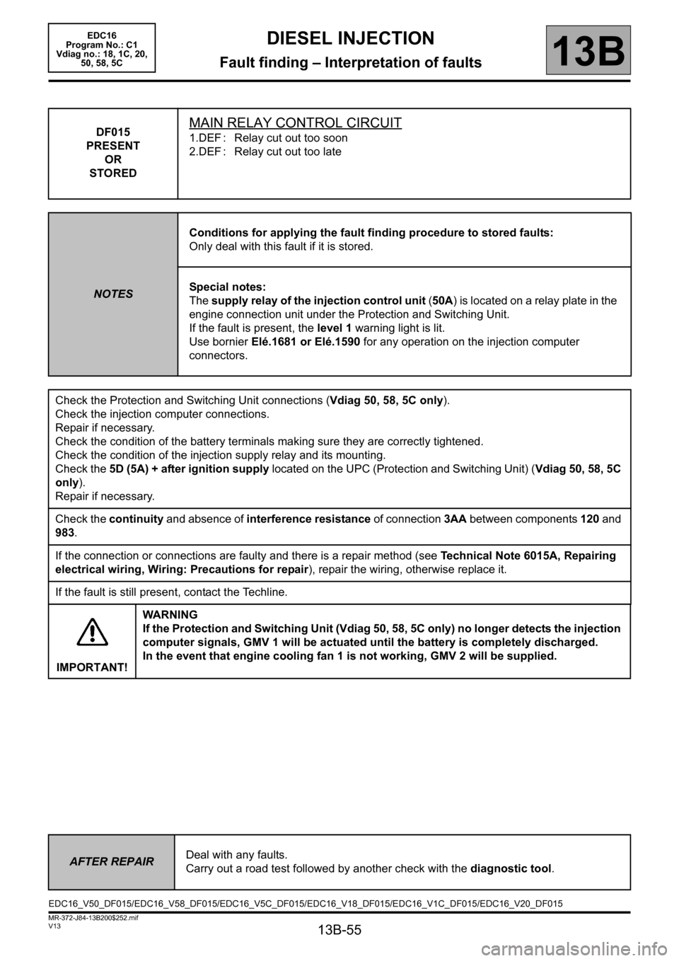
DF015
PRESENT
OR
STOREDMAIN RELAY CONTROL CIRCUIT
1.DEF : Relay cut out too soon
2.DEF : Relay cut out too late
NOTESConditions for applying the fault finding procedure to stored faults:
Only deal with this fault if it is stored.
Special notes:
The supply relay of the injection control unit (50A) is located on a relay plate in the
engine connection unit under the Protection and Switching Unit.
If the fault is present, the level 1 warning light is lit.
Use bornier Elé.1681 or Elé.1590 for any operation on the injection computer
connectors.
Check the Protection and Switching Unit connections (Vdiag 50, 58, 5C only).
Check the injection computer connections.
Repair if necessary.
Check the condition of the battery terminals making sure they are correctly tightened.
Check the condition of the injection supply relay and its mounting.
Check the 5D (5A) + after ignition supply located on the UPC (Protection and Switching Unit) (Vdiag 50, 58, 5C
only).
Repair if necessary.
Check the continuity and absence of interference resistance of connection 3AA between components 120 and
983.
If the connection or connections are faulty and there is a repair method (see Technical Note 6015A, Repairing
electrical wiring, Wiring: Precautions for repair), repair the wiring, otherwise replace it.
If the fault is still present, contact the Techline.
IMPORTANT!WA R N I N G
If the Protection and Switching Unit (Vdiag 50, 58, 5C only) no longer detects the injection
computer signals, GMV 1 will be actuated until the battery is completely discharged.
In the event that engine cooling fan 1 is not working, GMV 2 will be supplied.
AFTER REPAIRDeal with any faults.
Carry out a road test followed by another check with the diagnostic tool.
EDC16_V50_DF015/EDC16_V58_DF015/EDC16_V5C_DF015/EDC16_V18_DF015/EDC16_V1C_DF015/EDC16_V20_DF015
Page 56 of 365
13B-56
MR-372-J84-13B200$252.mif
V13
DIESEL INJECTION
Fault finding – Interpretation of faults
EDC16
Program No.: C1
Vdiag no.: 18, 1C, 20,
50, 58, 5C
13B
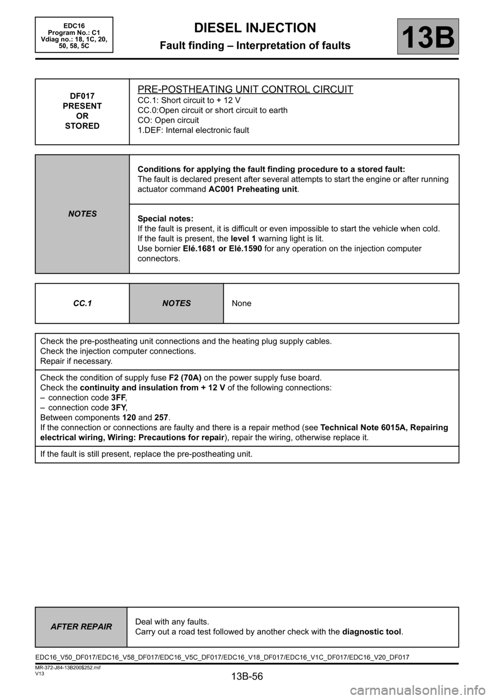
DF017
PRESENT
OR
STOREDPRE-POSTHEATING UNIT CONTROL CIRCUIT
CC.1: Short circuit to + 12 V
CC.0:Open circuit or short circuit to earth
CO: Open circuit
1.DEF: Internal electronic fault
NOTESConditions for applying the fault finding procedure to a stored fault:
The fault is declared present after several attempts to start the engine or after running
actuator command AC001 Preheating unit.
Special notes:
If the fault is present, it is difficult or even impossible to start the vehicle when cold.
If the fault is present, the level 1 warning light is lit.
Use bornier Elé.1681 or Elé.1590 for any operation on the injection computer
connectors.
CC.1
NOTESNone
Check the pre-postheating unit connections and the heating plug supply cables.
Check the injection computer connections.
Repair if necessary.
Check the condition of supply fuse F2 (70A) on the power supply fuse board.
Check the continuity and insulation from + 12 V of the following connections:
– connection code 3FF,
– connection code3FY,
Between components 120 and 257.
If the connection or connections are faulty and there is a repair method (see Technical Note 6015A, Repairing
electrical wiring, Wiring: Precautions for repair), repair the wiring, otherwise replace it.
If the fault is still present, replace the pre-postheating unit.
AFTER REPAIRDeal with any faults.
Carry out a road test followed by another check with the diagnostic tool.
EDC16_V50_DF017/EDC16_V58_DF017/EDC16_V5C_DF017/EDC16_V18_DF017/EDC16_V1C_DF017/EDC16_V20_DF017
Page 58 of 365
13B-58
MR-372-J84-13B200$252.mif
V13
DIESEL INJECTION
Fault finding – Interpretation of faults
EDC16
Program No.: C1
Vdiag no.: 18, 1C, 20,
50, 58, 5C
13B
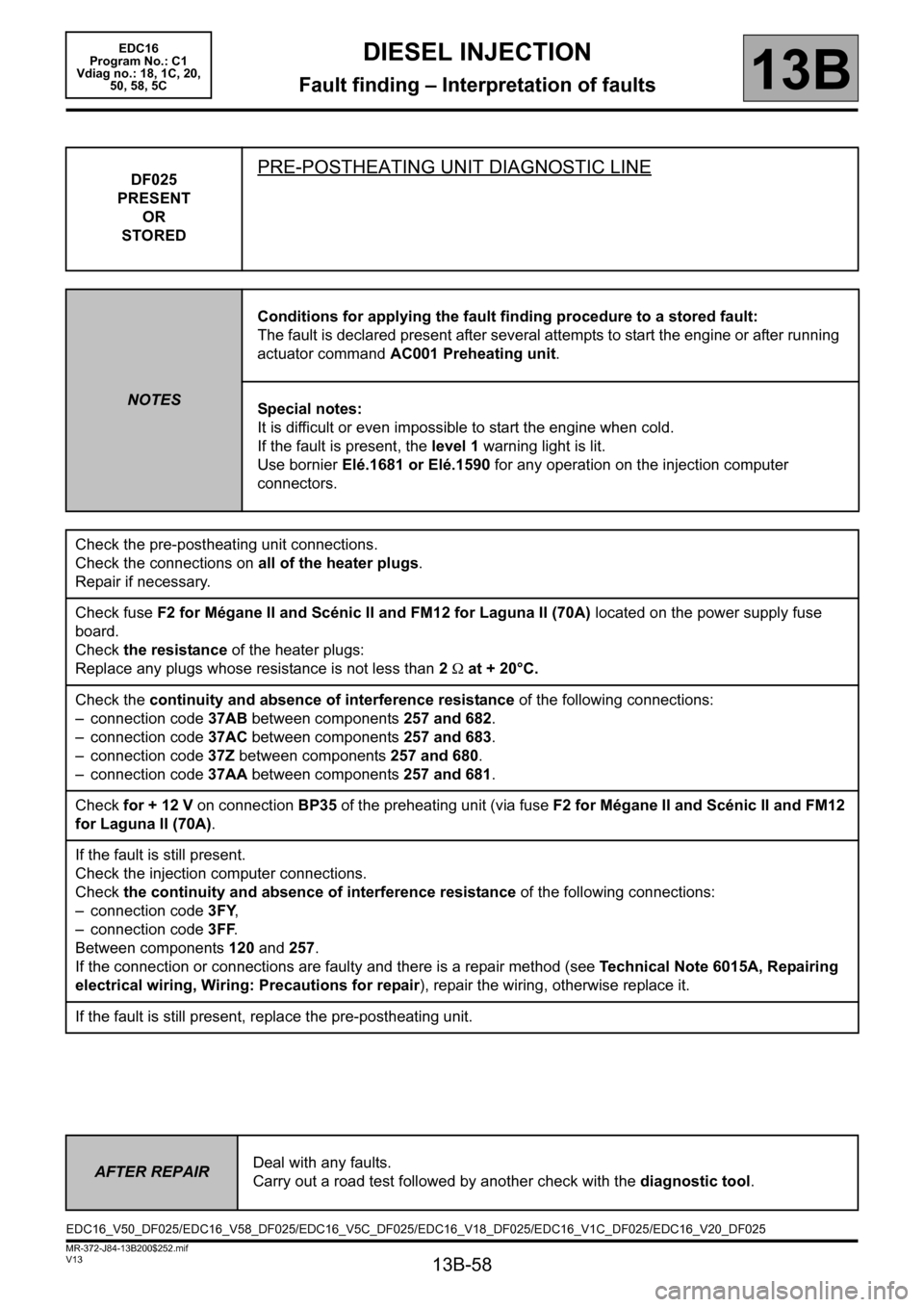
DF025
PRESENT
OR
STOREDPRE-POSTHEATING UNIT DIAGNOSTIC LINE
NOTESConditions for applying the fault finding procedure to a stored fault:
The fault is declared present after several attempts to start the engine or after running
actuator command AC001 Preheating unit.
Special notes:
It is difficult or even impossible to start the engine when cold.
If the fault is present, the level 1 warning light is lit.
Use bornier Elé.1681 or Elé.1590 for any operation on the injection computer
connectors.
Check the pre-postheating unit connections.
Check the connections on all of the heater plugs.
Repair if necessary.
Check fuse F2 for Mégane II and Scénic II and FM12 for Laguna II (70A) located on the power supply fuse
board.
Check the resistance of the heater plugs:
Replace any plugs whose resistance is not less than 2 Ω at + 20°C.
Check the continuity and absence of interference resistance of the following connections:
– connection code 37AB between components 257 and 682.
– connection code 37AC between components 257 and 683.
– connection code 37Z between components 257 and 680.
– connection code 37AA between components 257 and 681.
Check for + 12 V on connection BP35 of the preheating unit (via fuse F2 for Mégane II and Scénic II and FM12
for Laguna II (70A).
If the fault is still present.
Check the injection computer connections.
Check the continuity and absence of interference resistance of the following connections:
– connection code3FY,
– connection code 3FF.
Between components 120 and 257.
If the connection or connections are faulty and there is a repair method (see Technical Note 6015A, Repairing
electrical wiring, Wiring: Precautions for repair), repair the wiring, otherwise replace it.
If the fault is still present, replace the pre-postheating unit.
AFTER REPAIRDeal with any faults.
Carry out a road test followed by another check with the diagnostic tool.
EDC16_V50_DF025/EDC16_V58_DF025/EDC16_V5C_DF025/EDC16_V18_DF025/EDC16_V1C_DF025/EDC16_V20_DF025
Page 59 of 365

13B-59
MR-372-J84-13B200$252.mif
V13
13B
DIESEL INJECTION
Fault finding – Interpretation of faults
DF032
PRESENT
OR
STOREDTHERMOPLUNGER 1 RELAY CONTROL CIRCUIT
CO: Open circuit
CC.0: Short circuit to earth
CC.1 : Short circuit to + 12 V
1.DEF: Inconsistent signal
NOTESConditions for applying the fault finding procedure to stored faults:
The fault is declared present after:
– the ignition is switched on,
– with the engine running,
– actuator command AC063 Thermoplunger no. 1 relay.
If faults DF033 “Thermoplunger relay 2 control circuit” and DF034
“Thermoplunger relay 3 control circuit” appear, ignore them and go straight to
configuration CF030 “Thermoplunger configuration”.
Special notes:
Use bornier Elé. 1681 for all operations on the engine management computer
connectors.
check the engine management computer connections.
Check the thermoplunger connections, component code 898.
Repair if necessary.
Check for + 12 V after ignition supply on connections BP27 and BP35 of component 1550.
If there is no + 12 V supply, refer to the interpretation of fault DF015 Main relay control circuit.
Repair if necessary.
Check the continuity and absence of interference resistance of connection 3JA between components 120
and 1550.
If the connection or connections are faulty and there is a repair method (see Technical Note 6015A, Repairing
electrical wiring, Wiring: Precautions for repair), repair the wiring, otherwise replace it.
Using a test light, check the supply by running command AC063 Thermoplunger no. 1 relay on connection 3JB
between components 898 and 1550.
Measure the resistance of the thermoplunger, component code 898.
Replace the thermoplunger, component code 898 if the resistance is greater than 2 Ω.
Replace the water heater interface unit if necessary.
Using a test light, check that the water heater interface unit is properly earthed by running command AC063
Thermoplunger no. 1 relay on connection 3JA between components 120 and 1550.
If the fault is still present, contact the Techline.
AFTER REPAIRDeal with any faults.
Carry out a road test followed by another check with the diagnostic tool.
EDC16_V50_DF032/EDC16_V58_DF032/EDC16_V5C_DF032EDC16
Program No.: C1
Vdiag No.: 50, 58, 5C