sensor RENAULT SCENIC 2011 J95 / 3.G Engine And Peripherals EDC16 Service Manual
[x] Cancel search | Manufacturer: RENAULT, Model Year: 2011, Model line: SCENIC, Model: RENAULT SCENIC 2011 J95 / 3.GPages: 365, PDF Size: 2.11 MB
Page 84 of 365
13B-84
MR-372-J84-13B200$288.mif
V13
DIESEL INJECTION
Fault finding – Interpretation of faults
EDC16
Program No.: C1
Vdiag no.: 18, 1C, 20,
50, 58, 5C
13B
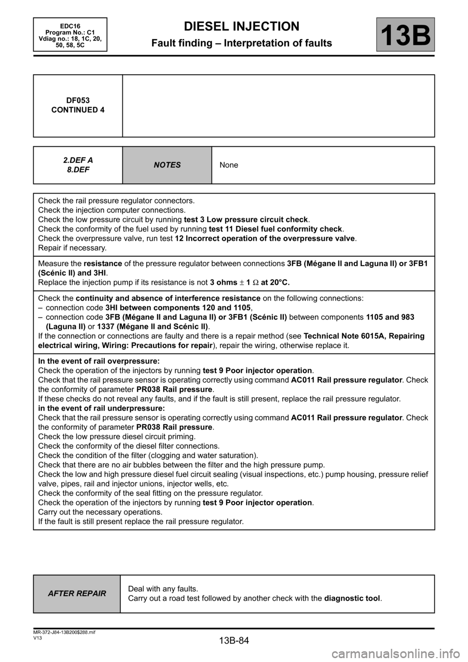
DF053
CONTINUED 4
2.DEF A
8.DEF
NOTESNone
Check the rail pressure regulator connectors.
Check the injection computer connections.
Check the low pressure circuit by running test 3 Low pressure circuit check.
Check the conformity of the fuel used by running test 11 Diesel fuel conformity check.
Check the overpressure valve, run test 12 Incorrect operation of the overpressure valve.
Repair if necessary.
Measure the resistance of the pressure regulator between connections 3FB (Mégane II and Laguna II) or 3FB1
(Scénic II) and 3HI.
Replace the injection pump if its resistance is not 3 ohms ± 1 Ω at 20°C.
Check the continuity and absence of interference resistance on the following connections:
– connection code 3HI between components 120 and 1105,
– connection code 3FB (Mégane II and Laguna II) or 3FB1 (Scénic II) between components 1105 and 983
(Laguna II) or 1337 (Mégane II and Scénic II).
If the connection or connections are faulty and there is a repair method (see Technical Note 6015A, Repairing
electrical wiring, Wiring: Precautions for repair), repair the wiring, otherwise replace it.
In the event of rail overpressure:
Check the operation of the injectors by running test 9 Poor injector operation.
Check that the rail pressure sensor is operating correctly using command AC011 Rail pressure regulator. Check
the conformity of parameter PR038 Rail pressure.
If these checks do not reveal any faults, and if the fault is still present, replace the rail pressure regulator.
in the event of rail underpressure:
Check that the rail pressure sensor is operating correctly using command AC011 Rail pressure regulator. Check
the conformity of parameter PR038 Rail pressure.
Check the low pressure diesel circuit priming.
Check the conformity of the diesel filter connections.
Check the condition of the filter (clogging and water saturation).
Check that there are no air bubbles between the filter and the high pressure pump.
Check the low and high pressure diesel fuel circuit sealing (visual inspections, etc.) pump housing, pressure relief
valve, pipes, rail and injector unions, injector wells, etc.
Check the conformity of the seal fitting on the pressure regulator.
Check the operation of the injectors by running test 9 Poor injector operation.
Carry out the necessary operations.
If the fault is still present replace the rail pressure regulator.
AFTER REPAIRDeal with any faults.
Carry out a road test followed by another check with the diagnostic tool.
Page 89 of 365
13B-89
MR-372-J84-13B200$288.mif
V13
DIESEL INJECTION
Fault finding – Interpretation of faults
EDC16
Program No.: C1
Vdiag no.: 18, 1C, 20,
50, 58, 5C
13B
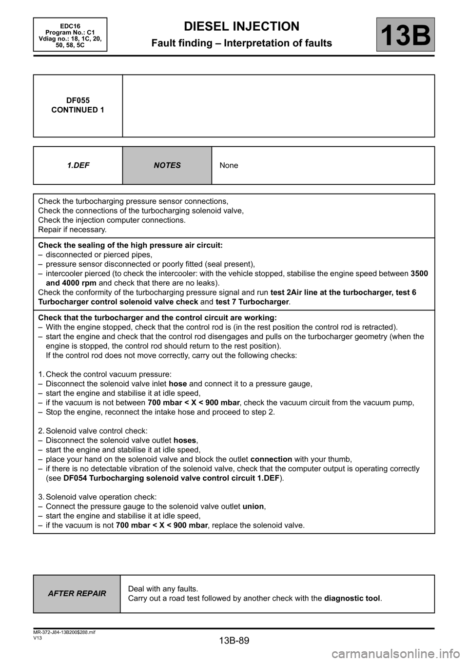
DF055
CONTINUED 1
1.DEF
NOTESNone
Check the turbocharging pressure sensor connections,
Check the connections of the turbocharging solenoid valve,
Check the injection computer connections.
Repair if necessary.
Check the sealing of the high pressure air circuit:
– disconnected or pierced pipes,
– pressure sensor disconnected or poorly fitted (seal present),
– intercooler pierced (to check the intercooler: with the vehicle stopped, stabilise the engine speed between 3500
and 4000 rpm and check that there are no leaks).
Check the conformity of the turbocharging pressure signal and run test 2Air line at the turbocharger, test 6
Turbocharger control solenoid valve check and test 7 Turbocharger.
Check that the turbocharger and the control circuit are working:
– With the engine stopped, check that the control rod is (in the rest position the control rod is retracted).
– start the engine and check that the control rod disengages and pulls on the turbocharger geometry (when the
engine is stopped, the control rod should return to the rest position).
If the control rod does not move correctly, carry out the following checks:
1. Check the control vacuum pressure:
– Disconnect the solenoid valve inlet hose and connect it to a pressure gauge,
– start the engine and stabilise it at idle speed,
– if the vacuum is not between 700 mbar < X < 900 mbar, check the vacuum circuit from the vacuum pump,
– Stop the engine, reconnect the intake hose and proceed to step 2.
2. Solenoid valve control check:
– Disconnect the solenoid valve outlet hoses,
– start the engine and stabilise it at idle speed,
– place your hand on the solenoid valve and block the outlet connection with your thumb,
– if there is no detectable vibration of the solenoid valve, check that the computer output is operating correctly
(see DF054 Turbocharging solenoid valve control circuit 1.DEF).
3. Solenoid valve operation check:
– Connect the pressure gauge to the solenoid valve outlet union,
– start the engine and stabilise it at idle speed,
– if the vacuum is not 700 mbar < X < 900 mbar, replace the solenoid valve.
AFTER REPAIRDeal with any faults.
Carry out a road test followed by another check with the diagnostic tool.
Page 90 of 365
13B-90
MR-372-J84-13B200$288.mif
V13
DIESEL INJECTION
Fault finding – Interpretation of faults
EDC16
Program No.: C1
Vdiag no.: 18, 1C, 20,
50, 58, 5C
13B
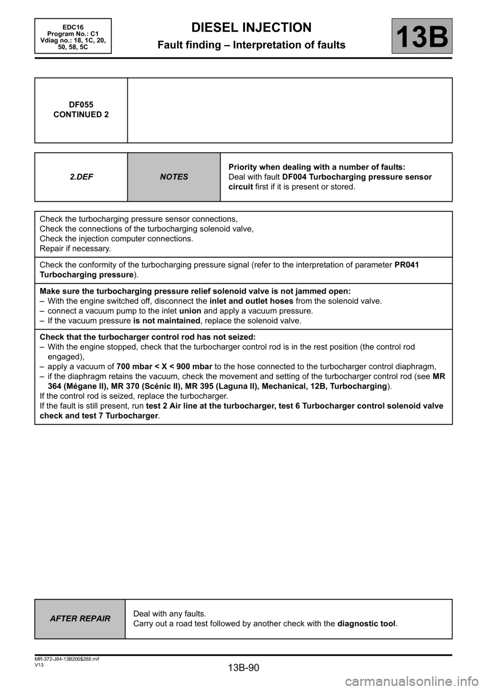
DF055
CONTINUED 2
2.DEF
NOTESPriority when dealing with a number of faults:
Deal with fault DF004 Turbocharging pressure sensor
circuit first if it is present or stored.
Check the turbocharging pressure sensor connections,
Check the connections of the turbocharging solenoid valve,
Check the injection computer connections.
Repair if necessary.
Check the conformity of the turbocharging pressure signal (refer to the interpretation of parameter PR041
Turbocharging pressure).
Make sure the turbocharging pressure relief solenoid valve is not jammed open:
– With the engine switched off, disconnect the inlet and outlet hoses from the solenoid valve.
– connect a vacuum pump to the inlet union and apply a vacuum pressure.
– If the vacuum pressure is not maintained, replace the solenoid valve.
Check that the turbocharger control rod has not seized:
– With the engine stopped, check that the turbocharger control rod is in the rest position (the control rod
engaged),
– apply a vacuum of 700 mbar < X < 900 mbar to the hose connected to the turbocharger control diaphragm,
– if the diaphragm retains the vacuum, check the movement and setting of the turbocharger control rod (see MR
364 (Mégane II), MR 370 (Scénic II), MR 395 (Laguna II), Mechanical, 12B, Turbocharging).
If the control rod is seized, replace the turbocharger.
If the fault is still present, run test 2 Air line at the turbocharger, test 6 Turbocharger control solenoid valve
check and test 7 Turbocharger.
AFTER REPAIRDeal with any faults.
Carry out a road test followed by another check with the diagnostic tool.
Page 91 of 365
13B-91
MR-372-J84-13B200$288.mif
V13
DIESEL INJECTION
Fault finding – Interpretation of faults
EDC16
Program No.: C1
Vdiag no.: 18, 1C, 20,
50, 58, 5C
13B
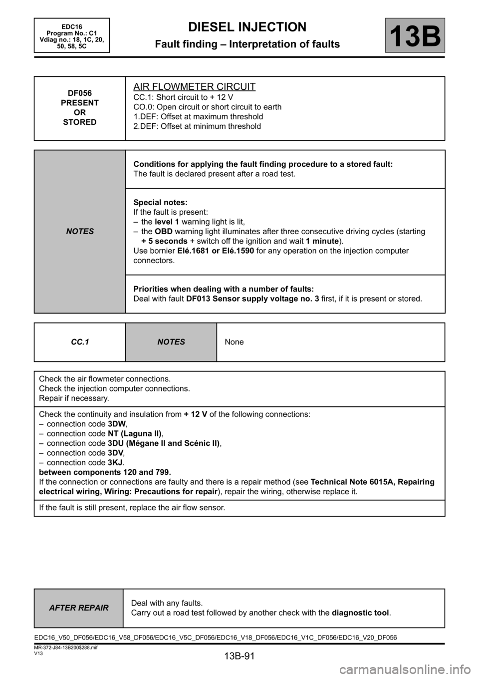
DF056
PRESENT
OR
STOREDAIR FLOWMETER CIRCUIT
CC.1: Short circuit to + 12 V
CO.0: Open circuit or short circuit to earth
1.DEF: Offset at maximum threshold
2.DEF: Offset at minimum threshold
NOTESConditions for applying the fault finding procedure to a stored fault:
The fault is declared present after a road test.
Special notes:
If the fault is present:
– the level 1 warning light is lit,
– the OBD warning light illuminates after three consecutive driving cycles (starting
+ 5 seconds + switch off the ignition and wait 1 minute).
Use bornier Elé.1681 or Elé.1590 for any operation on the injection computer
connectors.
Priorities when dealing with a number of faults:
Deal with fault DF013 Sensor supply voltage no. 3 first, if it is present or stored.
CC.1
NOTESNone
Check the air flowmeter connections.
Check the injection computer connections.
Repair if necessary.
Check the continuity and insulation from + 12 V of the following connections:
– connection code3DW,
– connection code NT (Laguna II),
– connection code 3DU (Mégane II and Scénic II),
– connection code3DV,
– connection code 3KJ.
between components 120 and 799.
If the connection or connections are faulty and there is a repair method (see Technical Note 6015A, Repairing
electrical wiring, Wiring: Precautions for repair), repair the wiring, otherwise replace it.
If the fault is still present, replace the air flow sensor.
AFTER REPAIRDeal with any faults.
Carry out a road test followed by another check with the diagnostic tool.
EDC16_V50_DF056/EDC16_V58_DF056/EDC16_V5C_DF056/EDC16_V18_DF056/EDC16_V1C_DF056/EDC16_V20_DF056
Page 92 of 365
13B-92
MR-372-J84-13B200$288.mif
V13
DIESEL INJECTION
Fault finding – Interpretation of faults
EDC16
Program No.: C1
Vdiag no.: 18, 1C, 20,
50, 58, 5C
13B
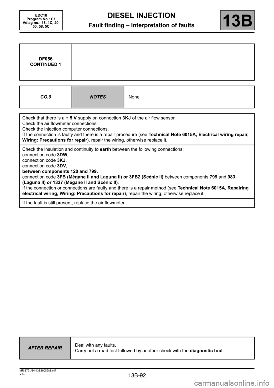
DF056
CONTINUED 1
CO.0
NOTESNone
Check that there is a + 5 V supply on connection 3KJ of the air flow sensor.
Check the air flowmeter connections.
Check the injection computer connections.
If the connection is faulty and there is a repair procedure (see Technical Note 6015A, Electrical wiring repair,
Wiring: Precautions for repair), repair the wiring, otherwise replace it.
Check the insulation and continuity to earth between the following connections:
connection code3DW,
connection code 3KJ,
connection code3DV,
between components 120 and 799.
connection code 3FB (Mégane II and Laguna II) or 3FB2 (Scénic II) between components 799 and 983
(Laguna II) or 1337 (Mégane II and Scénic II).
If the connection or connections are faulty and there is a repair method (see Technical Note 6015A, Repairing
electrical wiring, Wiring: Precautions for repair), repair the wiring, otherwise replace it.
If the fault is still present, replace the air flowmeter.
AFTER REPAIRDeal with any faults.
Carry out a road test followed by another check with the diagnostic tool.
Page 93 of 365
13B-93
MR-372-J84-13B200$288.mif
V13
DIESEL INJECTION
Fault finding – Interpretation of faults
EDC16
Program No.: C1
Vdiag no.: 18, 1C, 20,
50, 58, 5C
13B
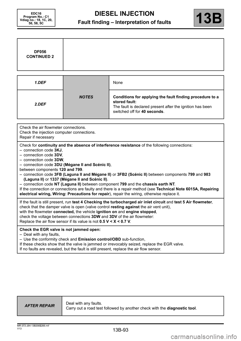
DF056
CONTINUED 2
1.DEF
NOTESNone
2.DEFConditions for applying the fault finding procedure to a
stored fault:
The fault is declared present after the ignition has been
switched off for 40 seconds.
Check the air flowmeter connections.
Check the injection computer connections.
Repair if necessary
Check for continuity and the absence of interference resistance of the following connections:
– connection code 3KJ,
– connection code3DV,
– connection code3DW,
– connection code 3DU (Mégane II and Scénic II),
between components 120 and 799.
– connection code 3FB (Laguna II and Mégane II) or 3FB2 (Scénic II) between components 799 and 983
(Laguna II) or 1337 (Mégane II and Scénic II).
– connection code NT (Laguna II) between component 799 and the chassis earth NT.
If the connection or connections are faulty and there is a repair method (see Technical Note 6015A, Repairing
electrical wiring, Wiring: Precautions for repair), repair the wiring, otherwise replace it.
If the fault is still present, run test 4 Checking the turbocharged air inlet circuit and test 5 Air flowmeter,
check that the damper valve is open (valve control resting against the air vent unit),
with the flowmeter connected, the vehicle ignition on and engine stopped,
check the voltage between connections 3DW and 3DV of the air flowmeter:
Replace the air flow sensor if its value is not 0.5 V < X < 0.7 V.
Check the EGR valve is not jammed open:
– Deal with any faults,
– Use the conformity check and Emission control/OBD sub-function,
If these checks show that the valve is jammed or irrevocably seized, replace the EGR valve.
If no faults are revealed, but the fault is still present, replace the air flow sensor.
AFTER REPAIRDeal with any faults.
Carry out a road test followed by another check with the diagnostic tool.
Page 94 of 365
13B-94
MR-372-J84-13B200$324.mif
V13
13B
DIESEL INJECTION
Fault finding – Interpretation of faults
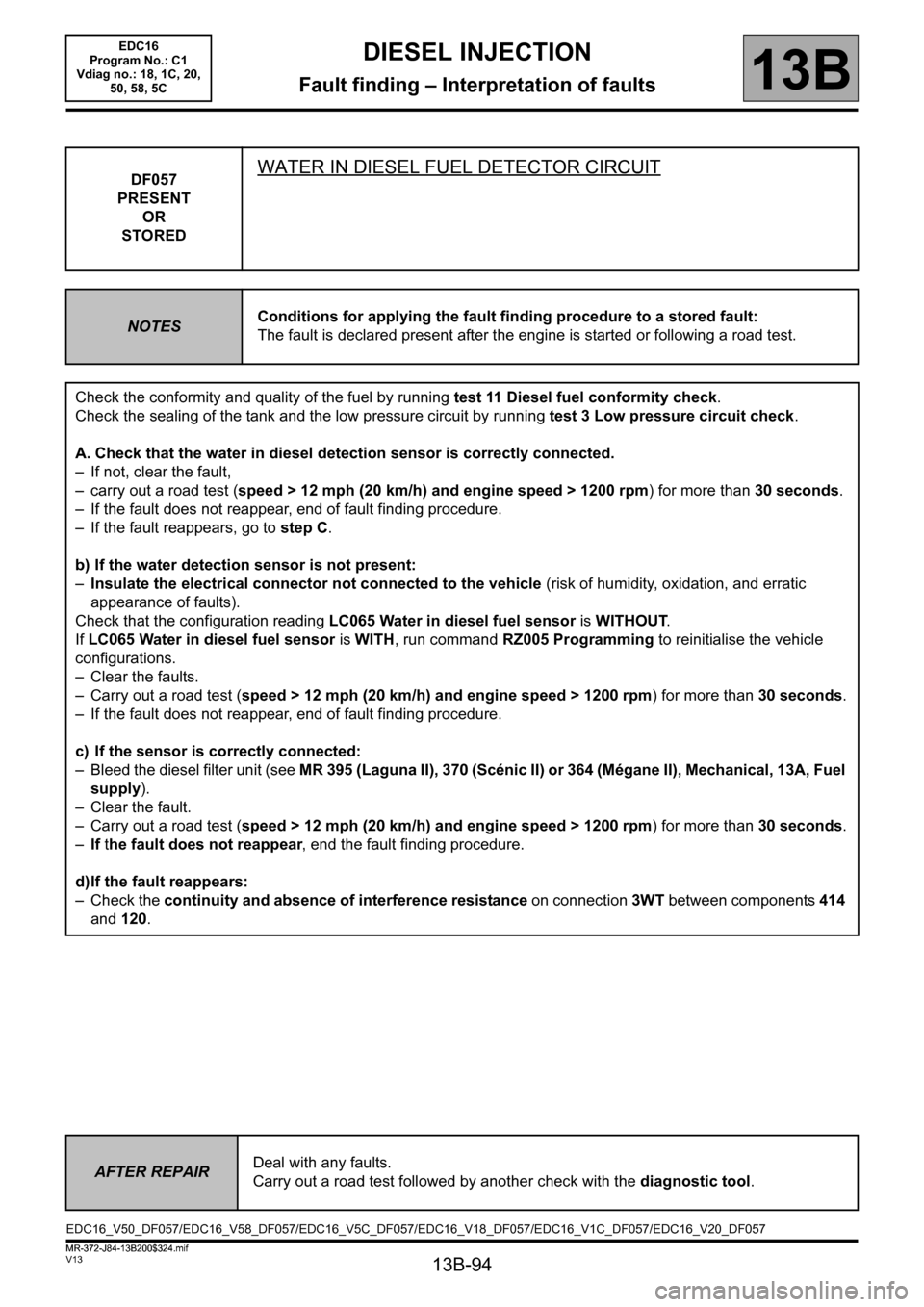
DF057
PRESENT
OR
STOREDWATER IN DIESEL FUEL DETECTOR CIRCUIT
NOTESConditions for applying the fault finding procedure to a stored fault:
The fault is declared present after the engine is started or following a road test.
Check the conformity and quality of the fuel by running test 11 Diesel fuel conformity check.
Check the sealing of the tank and the low pressure circuit by running test 3 Low pressure circuit check.
A. Check that the water in diesel detection sensor is correctly connected.
– If not, clear the fault,
– carry out a road test (speed > 12 mph (20 km/h) and engine speed > 1200 rpm) for more than 30 seconds.
– If the fault does not reappear, end of fault finding procedure.
– If the fault reappears, go to step C.
b) If the water detection sensor is not present:
–Insulate the electrical connector not connected to the vehicle (risk of humidity, oxidation, and erratic
appearance of faults).
Check that the configuration reading LC065 Water in diesel fuel sensor is WITHOUT.
If LC065 Water in diesel fuel sensor is WITH, run command RZ005 Programming to reinitialise the vehicle
configurations.
– Clear the faults.
– Carry out a road test (speed > 12 mph (20 km/h) and engine speed > 1200 rpm) for more than 30 seconds.
– If the fault does not reappear, end of fault finding procedure.
c) If the sensor is correctly connected:
– Bleed the diesel filter unit (see MR 395 (Laguna II), 370 (Scénic II) or 364 (Mégane II), Mechanical, 13A, Fuel
supply).
– Clear the fault.
– Carry out a road test (speed > 12 mph (20 km/h) and engine speed > 1200 rpm) for more than 30 seconds.
–If the fault does not reappear, end the fault finding procedure.
d)If the fault reappears:
– Check the continuity and absence of interference resistance on connection 3WT between components 414
and 120.
AFTER REPAIRDeal with any faults.
Carry out a road test followed by another check with the diagnostic tool.
EDC16_V50_DF057/EDC16_V58_DF057/EDC16_V5C_DF057/EDC16_V18_DF057/EDC16_V1C_DF057/EDC16_V20_DF057EDC16
Program No.: C1
Vdiag no.: 18, 1C, 20,
50, 58, 5C
MR-372-J84-13B200$324.mif
Page 95 of 365
13B-95
MR-372-J84-13B200$324.mif
V13
DIESEL INJECTION
Fault finding – Interpretation of faults
EDC16
Program No.: C1
Vdiag no.: 18, 1C, 20,
50, 58, 5C
13B
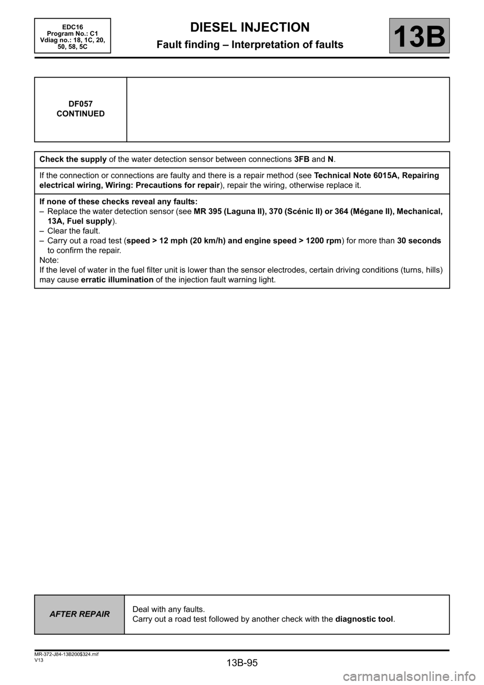
DF057
CONTINUED
Check the supply of the water detection sensor between connections 3FB and N.
If the connection or connections are faulty and there is a repair method (see Technical Note 6015A, Repairing
electrical wiring, Wiring: Precautions for repair), repair the wiring, otherwise replace it.
If none of these checks reveal any faults:
– Replace the water detection sensor (see MR 395 (Laguna II), 370 (Scénic II) or 364 (Mégane II), Mechanical,
13A, Fuel supply).
– Clear the fault.
– Carry out a road test (speed > 12 mph (20 km/h) and engine speed > 1200 rpm) for more than 30 seconds
to confirm the repair.
Note:
If the level of water in the fuel filter unit is lower than the sensor electrodes, certain driving conditions (turns, hills)
may cause erratic illumination of the injection fault warning light.
AFTER REPAIRDeal with any faults.
Carry out a road test followed by another check with the diagnostic tool.
Page 96 of 365
13B-96
MR-372-J84-13B200$324.mif
V13
DIESEL INJECTION
Fault finding – Interpretation of faults
EDC16
Program No.: C1
Vdiag no.: 18, 1C, 20,
50, 58, 5C
13B
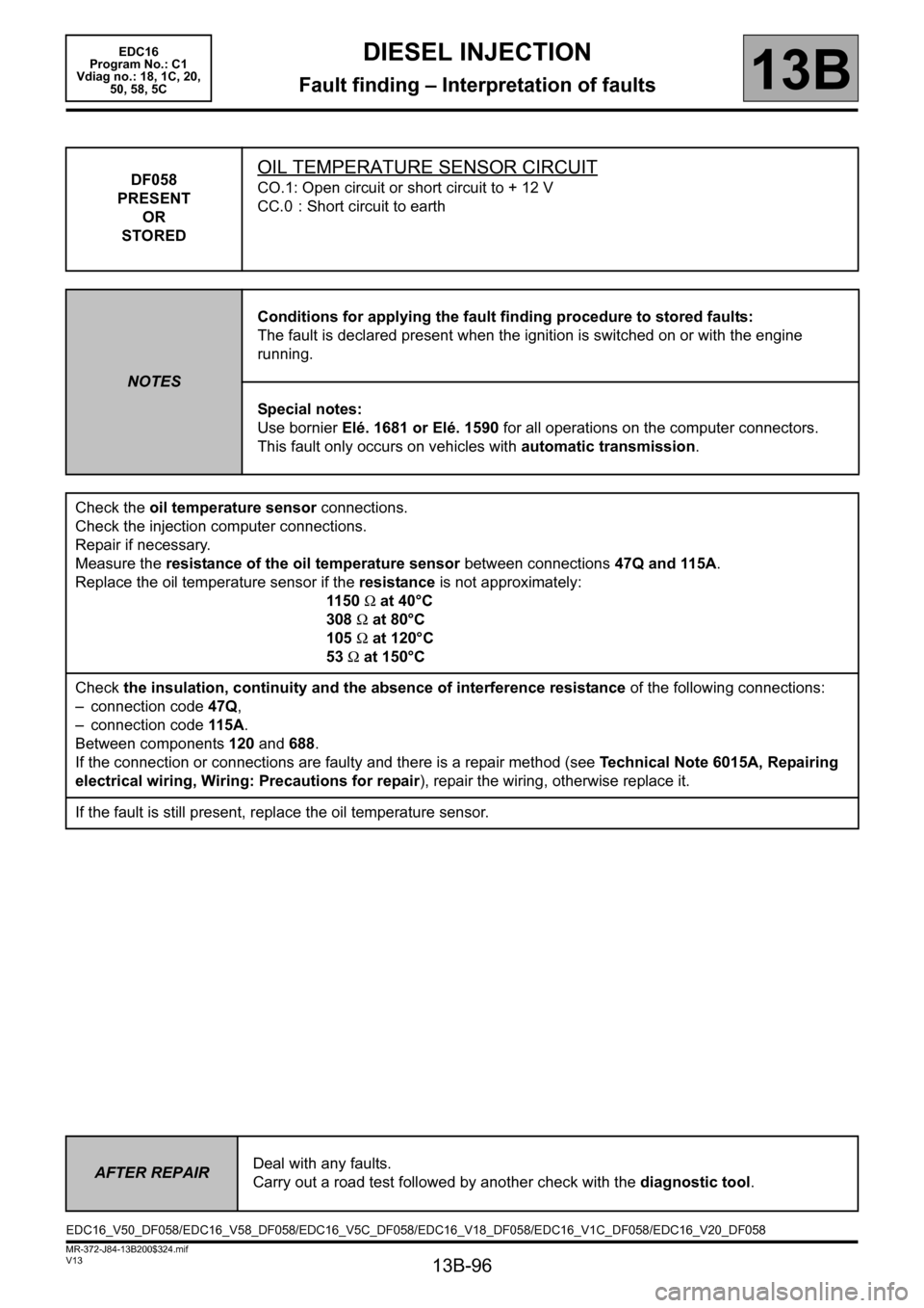
DF058
PRESENT
OR
STOREDOIL TEMPERATURE SENSOR CIRCUIT
CO.1: Open circuit or short circuit to + 12 V
CC.0 : Short circuit to earth
NOTESConditions for applying the fault finding procedure to stored faults:
The fault is declared present when the ignition is switched on or with the engine
running.
Special notes:
Use bornier Elé. 1681 or Elé. 1590 for all operations on the computer connectors.
This fault only occurs on vehicles with automatic transmission.
Check the oil temperature sensor connections.
Check the injection computer connections.
Repair if necessary.
Measure the resistance of the oil temperature sensor between connections 47Q and 115A.
Replace the oil temperature sensor if the resistance is not approximately:
11 50 Ω at 40°C
308 Ω at 80°C
105 Ω at 120°C
53 Ω at 150°C
Check the insulation, continuity and the absence of interference resistance of the following connections:
– connection code 47Q,
– connection code 115 A.
Between components 120 and 688.
If the connection or connections are faulty and there is a repair method (see Technical Note 6015A, Repairing
electrical wiring, Wiring: Precautions for repair), repair the wiring, otherwise replace it.
If the fault is still present, replace the oil temperature sensor.
AFTER REPAIRDeal with any faults.
Carry out a road test followed by another check with the diagnostic tool.
EDC16_V50_DF058/EDC16_V58_DF058/EDC16_V5C_DF058/EDC16_V18_DF058/EDC16_V1C_DF058/EDC16_V20_DF058
Page 106 of 365
13B-106
MR-372-J84-13B200$324.mif
V13
DIESEL INJECTION
Fault finding – Interpretation of faults
EDC16
Program No.: C1
Vdiag no.: 18, 1C, 20,
50, 58, 5C
13B
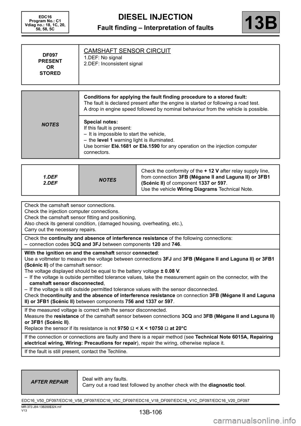
DF097
PRESENT
OR
STOREDCAMSHAFT SENSOR CIRCUIT
1.DEF: No signal
2.DEF: Inconsistent signal
NOTESConditions for applying the fault finding procedure to a stored fault:
The fault is declared present after the engine is started or following a road test.
A drop in engine speed followed by nominal behaviour from the vehicle is possible.
Special notes:
If this fault is present:
– It is impossible to start the vehicle,
– the level 1 warning light is illuminated.
Use bornier Elé.1681 or Elé.1590 for any operation on the injection computer
connectors.
1.DEF
2.DEF
NOTESCheck the conformity of the + 12 V after relay supply line,
from connection 3FB (Mégane II and Laguna II) or 3FB1
(Scénic II) of component 1337 or 597.
Use the vehicle Wiring Diagrams Technical Note.
Check the camshaft sensor connections.
Check the injection computer connections.
Check the camshaft sensor fitting and positioning,
Also check its general condition, (damaged housing, overheating, etc.),
Carry out the necessary repairs.
Check the continuity and absence of interference resistance of the following connections:
– connection codes 3CQ and 3FJ between components 120 and 746.
With the ignition on and the camshaft sensor connected:
Use a voltmeter to measure the voltage between connections 3FJ and 3FB (Mégane II and Laguna II) or 3FB1
(Scénic II) of the camshaft sensor:
The voltage displayed should be equal to the battery voltage ± 0.08 V.
– If the voltage is outside permitted tolerance values, take the measurement again on the connector, with the
camshaft sensor disconnected,
– If the voltage is still outside permitted tolerance values with the sensor disconnected.
Check thecontinuity and the absence of interference resistance on connection 3FB (Mégane II and Laguna
II) or 3FB1 (Scénic II) between components 756 and 1337 or 597.
If the measured voltage is correct with the sensor disconnected.
Measure the resistance of the camshaft sensor between connections 3CQ and 3FB (Mégane II and Laguna II)
or 3FB1 (Scénic II).
Replace the sensor if its resistance is not 9750 Ω < X < 10750 Ω at 20°C
If the connection or connections are faulty and there is a repair method (see Technical Note 6015A, Repairing
electrical wiring, Wiring: Precautions for repair), repair the wiring, otherwise replace it.
If the fault is still present, contact the Techline.
AFTER REPAIRDeal with any faults.
Carry out a road test followed by another check with the diagnostic tool.
EDC16_V50_DF097/EDC16_V58_DF097/EDC16_V5C_DF097/EDC16_V18_DF097/EDC16_V1C_DF097/EDC16_V20_DF097