check engine light RENAULT SCENIC 2011 J95 / 3.G Engine And Peripherals EDC16 Repair Manual
[x] Cancel search | Manufacturer: RENAULT, Model Year: 2011, Model line: SCENIC, Model: RENAULT SCENIC 2011 J95 / 3.GPages: 365, PDF Size: 2.11 MB
Page 148 of 365
13B-148
MR-372-J84-13B200$360.mif
V13
DIESEL INJECTION
Fault finding – Interpretation of faults
EDC16
Program No.: C1
Vdiag no.: 18, 1C, 20,
50, 58, 5C
13B
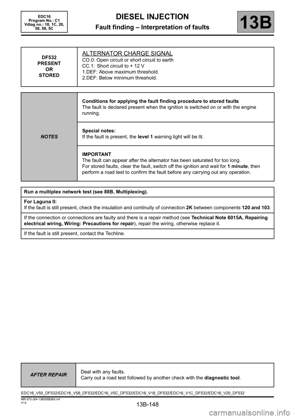
DF532
PRESENT
OR
STOREDALTERNATOR CHARGE SIGNAL
CO.0: Open circuit or short circuit to earth
CC.1: Short circuit to + 12 V
1.DEF: Above maximum threshold.
2.DEF: Below minimum threshold.
NOTESConditions for applying the fault finding procedure to stored faults
The fault is declared present when the ignition is switched on or with the engine
running.
Special notes:
If the fault is present, the level 1 warning light will be lit.
IMPORTANT
The fault can appear after the alternator has been saturated for too long.
For stored faults, clear the fault, switch off the ignition and wait for 1 minute, then
perform a road test to confirm the fault before any carrying out any operation.
Run a multiplex network test (see 88B, Multiplexing).
For Laguna II:
If the fault is still present, check the insulation and continuity of connection 2K between components 120 and 103.
If the connection or connections are faulty and there is a repair method (see Technical Note 6015A, Repairing
electrical wiring, Wiring: Precautions for repair), repair the wiring, otherwise replace it.
If the fault is still present, contact the Techline.
AFTER REPAIRDeal with any faults.
Carry out a road test followed by another check with the diagnostic tool.
EDC16_V50_DF532/EDC16_V58_DF532/EDC16_V5C_DF532/EDC16_V18_DF532/EDC16_V1C_DF532/EDC16_V20_DF532
Page 152 of 365
13B-152
MR-372-J84-13B200$360.mif
V13
DIESEL INJECTION
Fault finding – Interpretation of faults
EDC16
Program No.: C1
Vdiag no.: 18, 1C, 20,
50, 58, 5C
13B
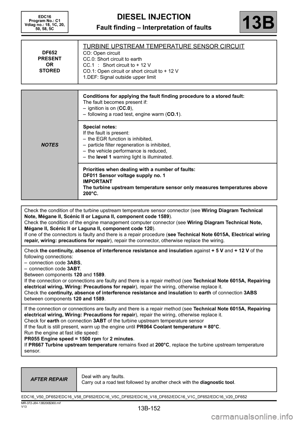
DF652
PRESENT
OR
STORED
TURBINE UPSTREAM TEMPERATURE SENSOR CIRCUIT
CO: Open circuit
CC.0: Short circuit to earth
CC.1 : Short circuit to + 12 V
CO.1: Open circuit or short circuit to + 12 V
1.DEF: Signal outside upper limit
NOTESConditions for applying the fault finding procedure to a stored fault:
The fault becomes present if:
– ignition is on (CC.0),
– following a road test, engine warm (CO.1).
Special notes:
If the fault is present:
– the EGR function is inhibited,
– particle filter regeneration is inhibited,
– the vehicle performance is reduced,
– the level 1 warning light is illuminated.
Priorities when dealing with a number of faults:
DF011 Sensor voltage supply no. 1
IMPORTANT
The turbine upstream temperature sensor only measures temperatures above
200°C.
Check the condition of the turbine upstream temperature sensor connector (see Wiring Diagram Technical
Note, Mégane II, Scénic II or Laguna II, component code 1589).
Check the condition of the engine management computer connector (see Wiring Diagram Technical Note,
Mégane II, Scénic II or Laguna II, component code 120).
If one of the connectors is faulty and there is a repair procedure (see Technical Note 6015A, Electrical wiring
repair, wiring: precautions for repair), repair the connector, otherwise replace the wiring.
Check the continuity, absence of interference resistance and insulation against + 5 V and + 12 V of the
following connections:
– connection code 3ABS,
– connection code 3ABT.
Between components 120 and 1589.
If the connection or connections are faulty and there is a repair method (see Technical Note 6015A, Repairing
electrical wiring, Wiring: Precautions for repair), repair the wiring, otherwise replace it.
Check the continuity, absence of interference resistance and insulation to earth of connection 3ABS
between components 120 and 1589.
If the connection or connections are faulty and there is a repair method (see Technical Note 6015A, Repairing
electrical wiring, Wiring: Precautions for repair), repair the wiring, otherwise replace it.
Check for earth on connection 3ABT of the turbine upstream temperature sensor
If the fault is still present, warm up the engine until PR064 Coolant temperature = 80°C.
Run the engine at fast idle speed:
PR055 Engine speed = 1500 rpm for 2 minutes.
If PR667 Turbine upstream temperature remains fixed at 200°C, replace the turbine upstream temperature
sensor.
AFTER REPAIRDeal with any faults.
Carry out a road test followed by another check with the diagnostic tool.
EDC16_V50_DF652/EDC16_V58_DF652/EDC16_V5C_DF652/EDC16_V18_DF652/EDC16_V1C_DF652/EDC16_V20_DF652
Page 153 of 365
13B-153
MR-372-J84-13B200$360.mif
V13
DIESEL INJECTION
Fault finding – Interpretation of faults
EDC16
Program No.: C1
Vdiag no.: 18, 1C, 20,
50, 58, 5C
13B
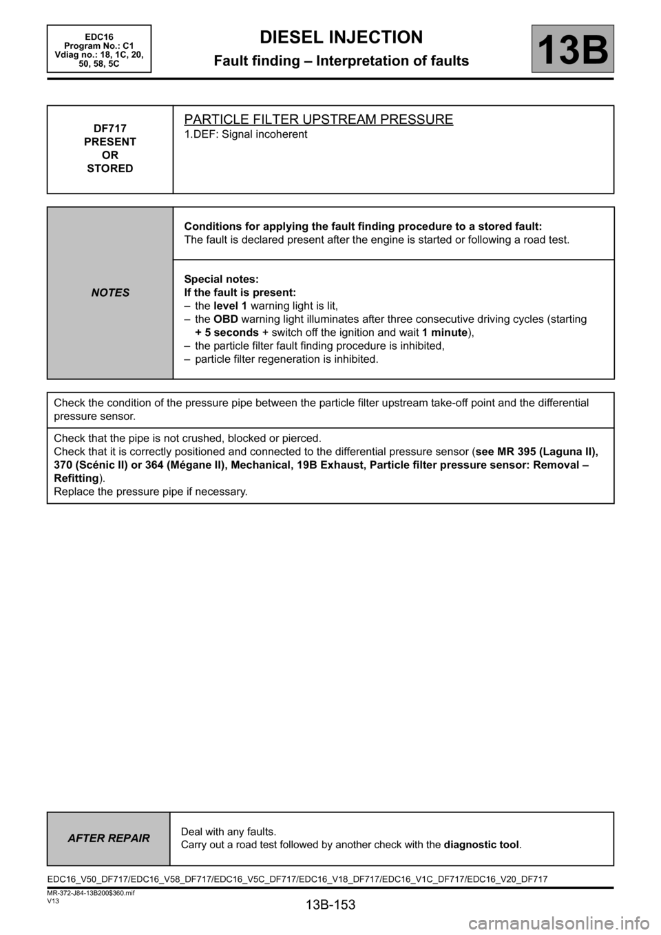
DF717
PRESENT
OR
STOREDPARTICLE FILTER UPSTREAM PRESSURE
1.DEF: Signal incoherent
NOTESConditions for applying the fault finding procedure to a stored fault:
The fault is declared present after the engine is started or following a road test.
Special notes:
If the fault is present:
– the level 1 warning light is lit,
– the OBD warning light illuminates after three consecutive driving cycles (starting
+ 5 seconds + switch off the ignition and wait 1 minute),
– the particle filter fault finding procedure is inhibited,
– particle filter regeneration is inhibited.
Check the condition of the pressure pipe between the particle filter upstream take-off point and the differential
pressure sensor.
Check that the pipe is not crushed, blocked or pierced.
Check that it is correctly positioned and connected to the differential pressure sensor (see MR 395 (Laguna II),
370 (Scénic II) or 364 (Mégane II), Mechanical, 19B Exhaust, Particle filter pressure sensor: Removal –
Refitting).
Replace the pressure pipe if necessary.
AFTER REPAIRDeal with any faults.
Carry out a road test followed by another check with the diagnostic tool.
EDC16_V50_DF717/EDC16_V58_DF717/EDC16_V5C_DF717/EDC16_V18_DF717/EDC16_V1C_DF717/EDC16_V20_DF717
Page 154 of 365
13B-154
MR-372-J84-13B200$360.mif
V13
DIESEL INJECTION
Fault finding – Interpretation of faults
EDC16
Program No.: C1
Vdiag no.: 18, 1C, 20,
50, 58, 5C
13B
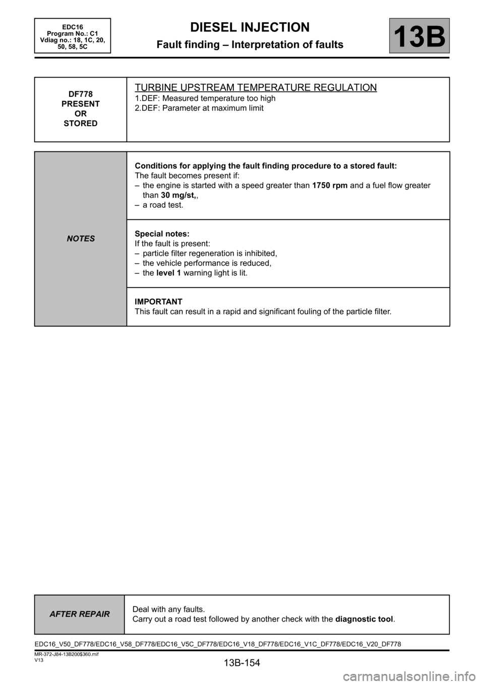
DF778
PRESENT
OR
STOREDTURBINE UPSTREAM TEMPERATURE REGULATION
1.DEF: Measured temperature too high
2.DEF: Parameter at maximum limit
NOTESConditions for applying the fault finding procedure to a stored fault:
The fault becomes present if:
– the engine is started with a speed greater than 1750 rpm and a fuel flow greater
than 30 mg/st,,
– a road test.
Special notes:
If the fault is present:
– particle filter regeneration is inhibited,
– the vehicle performance is reduced,
–the level 1 warning light is lit.
IMPORTANT
This fault can result in a rapid and significant fouling of the particle filter.
AFTER REPAIRDeal with any faults.
Carry out a road test followed by another check with the diagnostic tool.
EDC16_V50_DF778/EDC16_V58_DF778/EDC16_V5C_DF778/EDC16_V18_DF778/EDC16_V1C_DF778/EDC16_V20_DF778
Page 158 of 365
13B-158
MR-372-J84-13B200$360.mif
V13
DIESEL INJECTION
Fault finding – Interpretation of faults
EDC16
Program No.: C1
Vdiag no.: 18, 1C, 20,
50, 58, 5C
13B
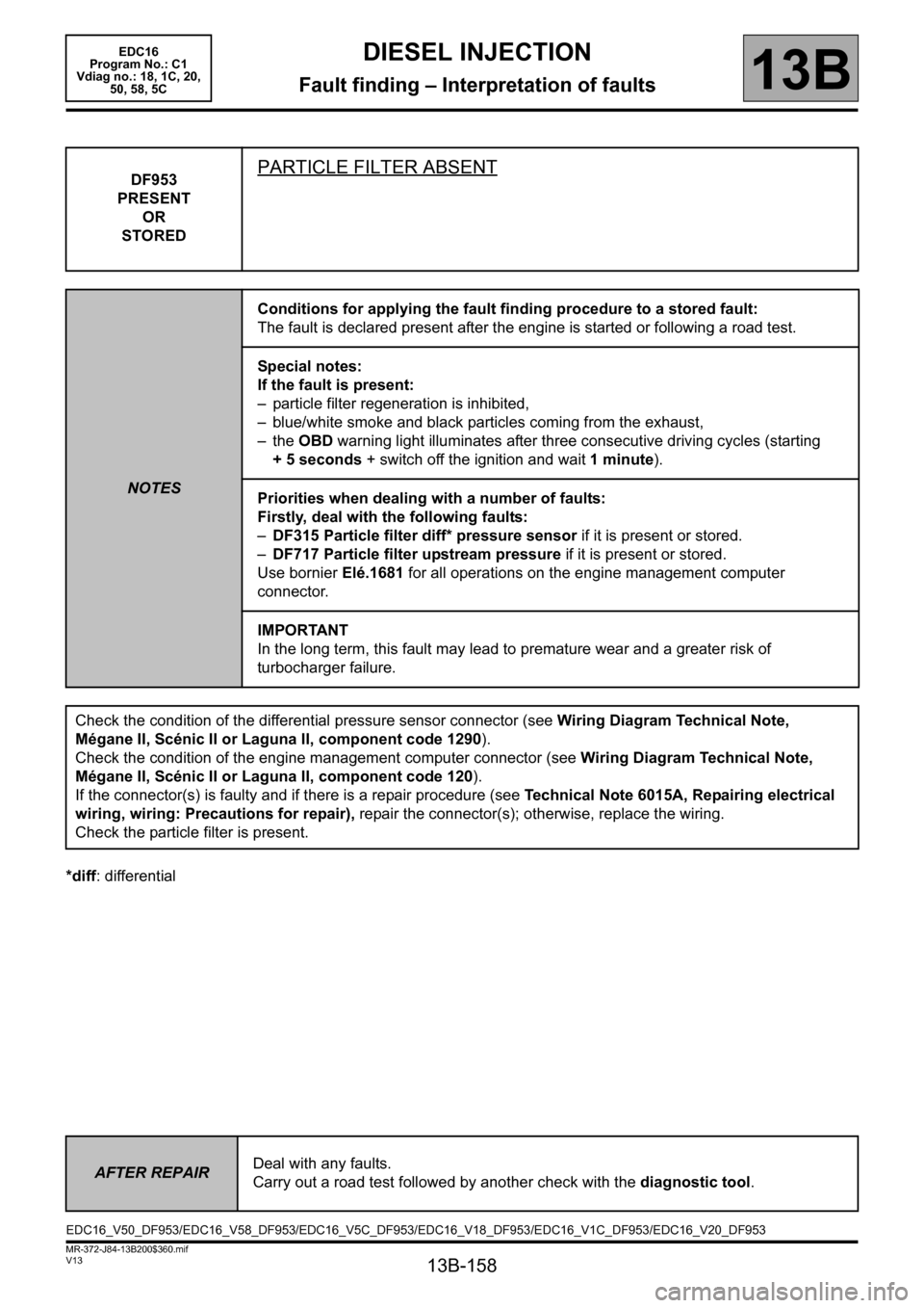
*diff: differentialDF953
PRESENT
OR
STORED
PARTICLE FILTER ABSENT
NOTESConditions for applying the fault finding procedure to a stored fault:
The fault is declared present after the engine is started or following a road test.
Special notes:
If the fault is present:
– particle filter regeneration is inhibited,
– blue/white smoke and black particles coming from the exhaust,
– the OBD warning light illuminates after three consecutive driving cycles (starting
+ 5 seconds + switch off the ignition and wait 1 minute).
Priorities when dealing with a number of faults:
Firstly, deal with the following faults:
–DF315 Particle filter diff* pressure sensor if it is present or stored.
–DF717 Particle filter upstream pressure if it is present or stored.
Use bornier Elé.1681 for all operations on the engine management computer
connector.
IMPORTANT
In the long term, this fault may lead to premature wear and a greater risk of
turbocharger failure.
Check the condition of the differential pressure sensor connector (see Wiring Diagram Technical Note,
Mégane II, Scénic II or Laguna II, component code 1290).
Check the condition of the engine management computer connector (see Wiring Diagram Technical Note,
Mégane II, Scénic II or Laguna II, component code 120).
If the connector(s) is faulty and if there is a repair procedure (see Technical Note 6015A, Repairing electrical
wiring, wiring: Precautions for repair), repair the connector(s); otherwise, replace the wiring.
Check the particle filter is present.
AFTER REPAIRDeal with any faults.
Carry out a road test followed by another check with the diagnostic tool.
EDC16_V50_DF953/EDC16_V58_DF953/EDC16_V5C_DF953/EDC16_V18_DF953/EDC16_V1C_DF953/EDC16_V20_DF953
Page 208 of 365
13B-208
MR-372-J84-13B200$540.mif
V13
DIESEL INJECTION
Fault finding – Interpretation of statuses
EDC16
Program No: C1
Vdiag No: 18, 1C, 20,
50, 58, 5C
13B
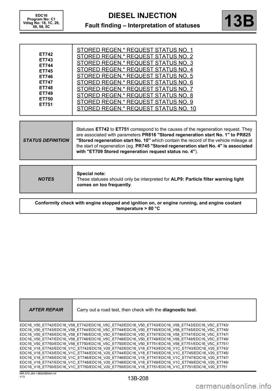
ET742
ET743
ET744
ET745
ET746
ET747
ET748
ET749
ET750
ET751STORED REGEN.* REQUEST STATUS NO. 1
STORED REGEN.* REQUEST STATUS NO. 2
STORED REGEN.* REQUEST STATUS NO. 3
STORED REGEN.* REQUEST STATUS NO. 4
STORED REGEN.* REQUEST STATUS NO. 5
STORED REGEN.* REQUEST STATUS NO. 6
STORED REGEN.* REQUEST STATUS NO. 7
STORED REGEN.* REQUEST STATUS NO. 8
STORED REGEN.* REQUEST STATUS NO. 9
STORED REGEN.* REQUEST STATUS NO. 10
STATUS DEFINITIONStatuses ET742 to ET751 correspond to the causes of the regeneration request. They
are associated with parameters PR816 "Stored regeneration start No. 1" to PR825
"Stored regeneration start No. 10" which contain the record of the vehicle mileage at
the start of regeneration (eg. PR745 "Stored regeneration start No. 4" is associated
with "ET709 Stored regeneration request status no. 4").
NOTESSpecial note:
These statuses should only be interpreted for ALP9: Particle filter warning light
comes on too frequently.
Conformity check with engine stopped and ignition on, or engine running, and engine coolant
temperature > 80 °C
AFTER REPAIRCarry out a road test, then check with the diagnostic tool.
EDC16_V50_ET742/EDC16_V58_ET742/EDC16_V5C_ET742/EDC16_V50_ET743/EDC16_V58_ET743/EDC16_V5C_ET743/
EDC16_V50_ET743/EDC16_V58_ET744/EDC16_V5C_ET744/EDC16_V50_ET745/EDC16_V58_ET745/EDC16_V5C_ET745/
EDC16_V50_ET745/EDC16_V58_ET746/EDC16_V5C_ET746/EDC16_V50_ET747/EDC16_V58_ET747/EDC16_V5C_ET747/
EDC16_V50_ET747/EDC16_V58_ET748/EDC16_V5C_ET748/EDC16_V50_ET749/EDC16_V58_ET749/EDC16_V5C_ET749/
EDC16_V50_ET750/EDC16_V58_ET750/EDC16_V5C_ET750/EDC16_V50_ET751/EDC16_V58_ET751/EDC16_V5C_ET751/
EDC16_V18_ET742/EDC16_V1C_ET742/EDC16_V20_ET742/EDC16_V18_ET743/EDC16_V1C_ET743/EDC16_V20_ET743/
EDC16_V18_ET743/EDC16_V1C_ET744/EDC16_V20_ET744/EDC16_V18_ET745/EDC16_V1C_ET745/EDC16_V20_ET745/
EDC16_V18_ET745/EDC16_V1C_ET746/EDC16_V20_ET746/EDC16_V18_ET747/EDC16_V1C_ET747/EDC16_V20_ET747/
EDC16_V18_ET747/EDC16_V1C_ET748/EDC16_V20_ET748/EDC16_V18_ET749/EDC16_V1C_ET749/EDC16_V20_ET749/
EDC16_V18_ET750/EDC16_V1C_ET750/EDC16_V20_ET750/EDC16_V18_ET751/EDC16_V1C_ET751/EDC16_V20_ET751
Page 288 of 365
13B-288
MR-372-J84-13B200$684.mif
V13
DIESEL INJECTION
Fault finding – Interpretation of parameters
EDC16
Program No: C1
Vdiag No: 18, 1C, 20,
50, 58, 5C
13B
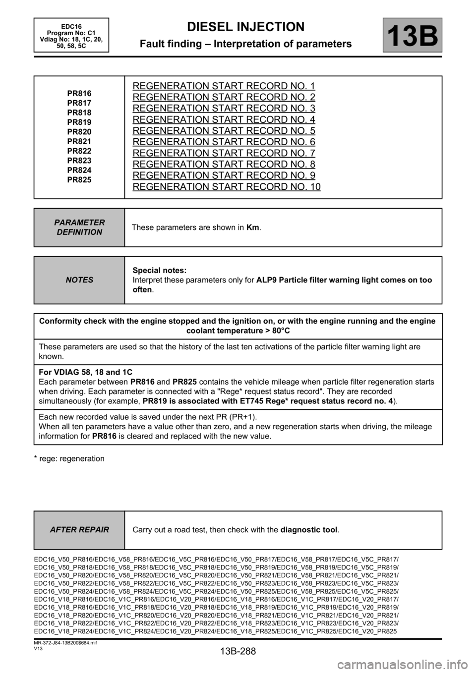
* rege: regenerationPR816
PR817
PR818
PR819
PR820
PR821
PR822
PR823
PR824
PR825
REGENERATION START RECORD NO. 1
REGENERATION START RECORD NO. 2
REGENERATION START RECORD NO. 3
REGENERATION START RECORD NO. 4
REGENERATION START RECORD NO. 5
REGENERATION START RECORD NO. 6
REGENERATION START RECORD NO. 7
REGENERATION START RECORD NO. 8
REGENERATION START RECORD NO. 9
REGENERATION START RECORD NO. 10
PARAMETER
DEFINITIONThese parameters are shown in Km.
NOTESSpecial notes:
Interpret these parameters only for ALP9 Particle filter warning light comes on too
often.
Conformity check with the engine stopped and the ignition on, or with the engine running and the engine
coolant temperature > 80°C
These parameters are used so that the history of the last ten activations of the particle filter warning light are
known.
For VDIAG 58, 18 and 1C
Each parameter between PR816 and PR825 contains the vehicle mileage when particle filter regeneration starts
when driving. Each parameter is connected with a "Rege* request status record". They are recorded
simultaneously (for example, PR819 is associated with ET745 Rege* request status record no. 4).
Each new recorded value is saved under the next PR (PR+1).
When all ten parameters have a value other than zero, and a new regeneration starts when driving, the mileage
information for PR816 is cleared and replaced with the new value.
AFTER REPAIRCarry out a road test, then check with the diagnostic tool.
EDC16_V50_PR816/EDC16_V58_PR816/EDC16_V5C_PR816/EDC16_V50_PR817/EDC16_V58_PR817/EDC16_V5C_PR817/
EDC16_V50_PR818/EDC16_V58_PR818/EDC16_V5C_PR818/EDC16_V50_PR819/EDC16_V58_PR819/EDC16_V5C_PR819/
EDC16_V50_PR820/EDC16_V58_PR820/EDC16_V5C_PR820/EDC16_V50_PR821/EDC16_V58_PR821/EDC16_V5C_PR821/
EDC16_V50_PR822/EDC16_V58_PR822/EDC16_V5C_PR822/EDC16_V50_PR823/EDC16_V58_PR823/EDC16_V5C_PR823/
EDC16_V50_PR824/EDC16_V58_PR824/EDC16_V5C_PR824/EDC16_V50_PR825/EDC16_V58_PR825/EDC16_V5C_PR825/
EDC16_V18_PR816/EDC16_V1C_PR816/EDC16_V20_PR816/EDC16_V18_PR816/EDC16_V1C_PR817/EDC16_V20_PR817/
EDC16_V18_PR816/EDC16_V1C_PR818/EDC16_V20_PR818/EDC16_V18_PR819/EDC16_V1C_PR819/EDC16_V20_PR819/
EDC16_V18_PR820/EDC16_V1C_PR820/EDC16_V20_PR820/EDC16_V18_PR821/EDC16_V1C_PR821/EDC16_V20_PR821/
EDC16_V18_PR822/EDC16_V1C_PR822/EDC16_V20_PR822/EDC16_V18_PR823/EDC16_V1C_PR823/EDC16_V20_PR823/
EDC16_V18_PR824/EDC16_V1C_PR824/EDC16_V20_PR824/EDC16_V18_PR825/EDC16_V1C_PR825/EDC16_V20_PR825
Page 293 of 365
13B-293
MR-372-J84-13B200$756.mif
V13
DIESEL INJECTION
Fault finding – Interpretation of commands
EDC16
Program No: C1
Vdiag No: 18, 1C, 20,
50, 58, 5C
13B
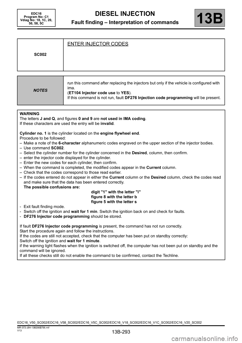
SC002
ENTER INJECTOR CODES
NOTESrun this command after replacing the injectors but only if the vehicle is configured with
ima.
(ET104 Injector code use to YES).
If this command is not run, fault DF276 Injection code programming will be present.
WARNING
The letters J and Q, and figures 0 and 9 are not used in IMA coding.
If these characters are used the entry will be invalid.
Cylinder no. 1 is the cylinder located on the engine flywheel end.
Procedure to be followed:
– Make a note of the 6-character alphanumeric codes engraved on the upper section of the injector bodies.
– Use command SC002.
– Select the cylinder number for the cylinder concerned in the Desired, column, then confirm.
– enter the injector code displayed for the cylinder.
– Enter the new codes for each cylinder, then confirm.
– When the command is completed, the modified codes appear in the Current column.
– Check that the codes correspond to those read earlier.
– If the codes entered do not appear in either the Current column or the Desired column, check the codes read
and make sure that the data has been entered correctly.
The possible confusions are:
digit "1" with the letter "i"
figure 8 with the letter b
figure 5 with the letter s
- Exit fault finding mode.
- Switch off the ignition and wait for 1 min. Switch the ignition back on and check for faults.
-DF276 Injector code programming should be stored.
If fault DF276 Injector code programming is present, the command has not run correctly.
Start the procedure again and follow the instructions.
If the codes are still not accepted, check that the computer has been put on standby correctly:
Switch off the ignition and wait for 1 minute.
if the warning light flashes when the ignition is switched off, the computer has not been put on standby and the
command will be ignored.
If all these checks still do not enable the command to be confirmed, contact the Techline.
EDC16_V50_SC002/EDC16_V58_SC002/EDC16_V5C_SC002/EDC16_V18_SC002/EDC16_V1C_SC002/EDC16_V20_SC002
Page 308 of 365
13B-308
MR-372-J84-13B200$756.mif
V13
DIESEL INJECTION
Fault finding – Interpretation of commands
EDC16
Program No: C1
Vdiag No: 18, 1C, 20,
50, 58, 5C
13B
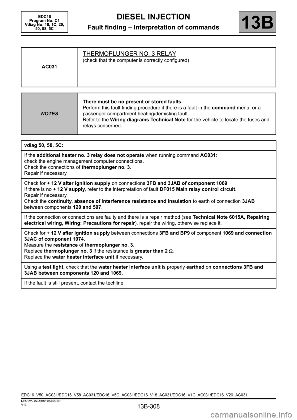
AC031
THERMOPLUNGER NO. 3 RELAY
(check that the computer is correctly configured)
NOTESThere must be no present or stored faults.
Perform this fault finding procedure if there is a fault in the command menu, or a
passenger compartment heating/demisting fault.
Refer to the Wiring diagrams Technical Note for the vehicle to locate the fuses and
relays concerned.
vdiag 50, 58, 5C:
If the additional heater no. 3 relay does not operate when running command AC031:
check the engine management computer connections.
Check the connections of thermoplunger no. 3.
Repair if necessary.
Check for + 12 V after ignition supply on connections 3FB and 3JAB of component 1069.
If there is no + 12 V supply, refer to the interpretation of fault DF015 Main relay control circuit.
Repair if necessary.
Check the continuity, absence of interference resistance and insulation to earth of connection 3JAB
between components 120 and 597.
If the connection or connections are faulty and there is a repair method (see Technical Note 6015A, Repairing
electrical wiring, Wiring: Precautions for repair), repair the wiring, otherwise replace it.
Check for + 12 V after ignition supply between connections 3FB and BP9 of component 1069 and connection
3JAC of component 1074.
Measure the resistance of thermoplunger no. 3.
Replace thermoplunger no. 3 if the resistance is greater than 2 Ω.
Replace the water heater interface unit if necessary.
Using a test light, check that the water heater interface unit is properly earthed on connections 3FB and
3JAB between components 120 and 1069.
If the fault is still present, contact the techline.
EDC16_V50_AC031/EDC16_V58_AC031/EDC16_V5C_AC031/EDC16_V18_AC031/EDC16_V1C_AC031/EDC16_V20_AC031
Page 312 of 365
13B-312
MR-372-J84-13B200$756.mif
V13
DIESEL INJECTION
Fault finding – Interpretation of commands
EDC16
Program No: C1
Vdiag No: 18, 1C, 20,
50, 58, 5C
13B
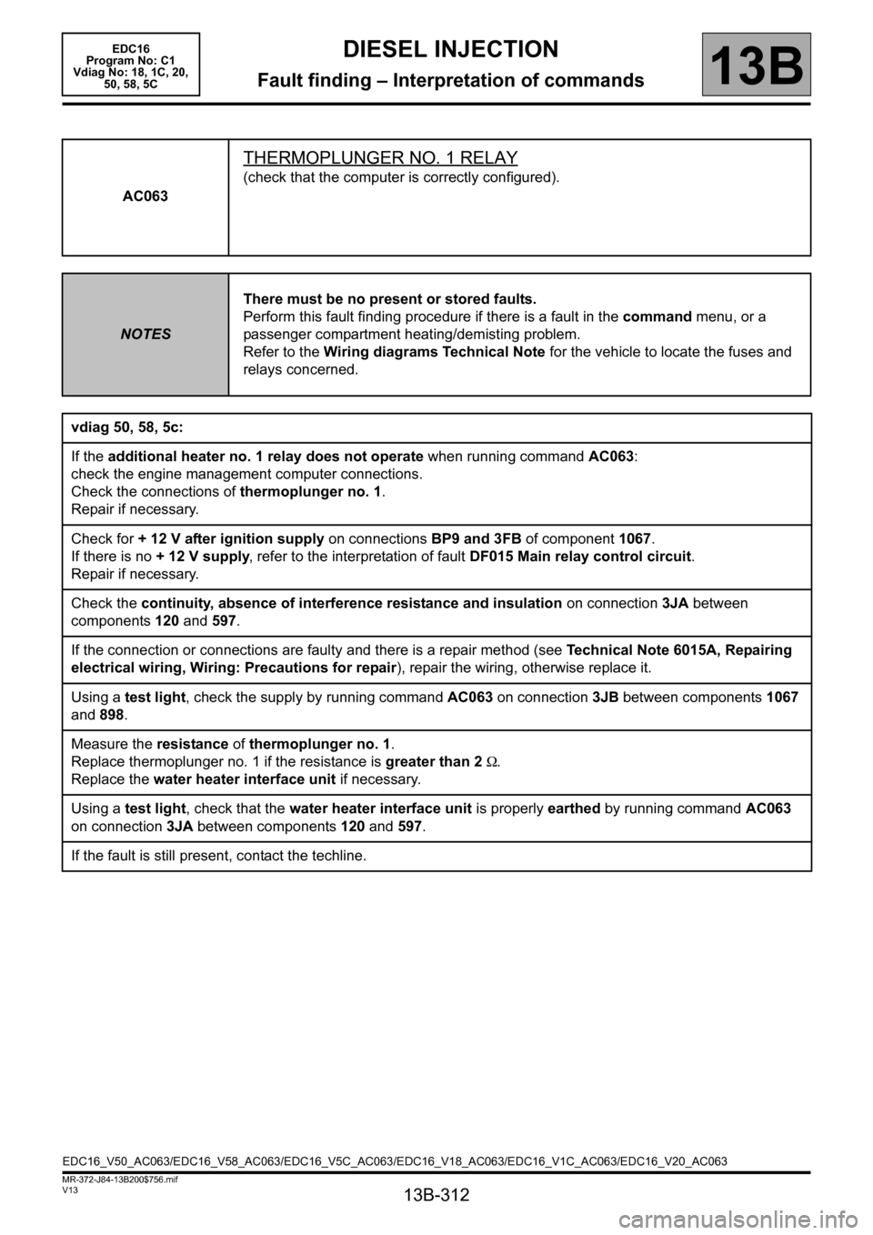
AC063
THERMOPLUNGER NO. 1 RELAY
(check that the computer is correctly configured).
NOTESThere must be no present or stored faults.
Perform this fault finding procedure if there is a fault in the command menu, or a
passenger compartment heating/demisting problem.
Refer to the Wiring diagrams Technical Note for the vehicle to locate the fuses and
relays concerned.
vdiag 50, 58, 5c:
If the additional heater no. 1 relay does not operate when running command AC063:
check the engine management computer connections.
Check the connections of thermoplunger no. 1.
Repair if necessary.
Check for + 12 V after ignition supply on connections BP9 and 3FB of component 1067.
If there is no + 12 V supply, refer to the interpretation of fault DF015 Main relay control circuit.
Repair if necessary.
Check the continuity, absence of interference resistance and insulation on connection 3JA between
components 120 and 597.
If the connection or connections are faulty and there is a repair method (see Technical Note 6015A, Repairing
electrical wiring, Wiring: Precautions for repair), repair the wiring, otherwise replace it.
Using a test light, check the supply by running command AC063 on connection 3JB between components 1067
and 898.
Measure the resistance of thermoplunger no. 1.
Replace thermoplunger no. 1 if the resistance is greater than 2 Ω.
Replace the water heater interface unit if necessary.
Using a test light, check that the water heater interface unit is properly earthed by running command AC063
on connection 3JA between components 120 and 597.
If the fault is still present, contact the techline.
EDC16_V50_AC063/EDC16_V58_AC063/EDC16_V5C_AC063/EDC16_V18_AC063/EDC16_V1C_AC063/EDC16_V20_AC063