check engine light RENAULT SCENIC 2011 J95 / 3.G Engine And Peripherals EDC16 Repair Manual
[x] Cancel search | Manufacturer: RENAULT, Model Year: 2011, Model line: SCENIC, Model: RENAULT SCENIC 2011 J95 / 3.GPages: 365, PDF Size: 2.11 MB
Page 314 of 365
13B-314
MR-372-J84-13B200$756.mif
V13
DIESEL INJECTION
Fault finding – Interpretation of commands
EDC16
Program No: C1
Vdiag No: 18, 1C, 20,
50, 58, 5C
13B
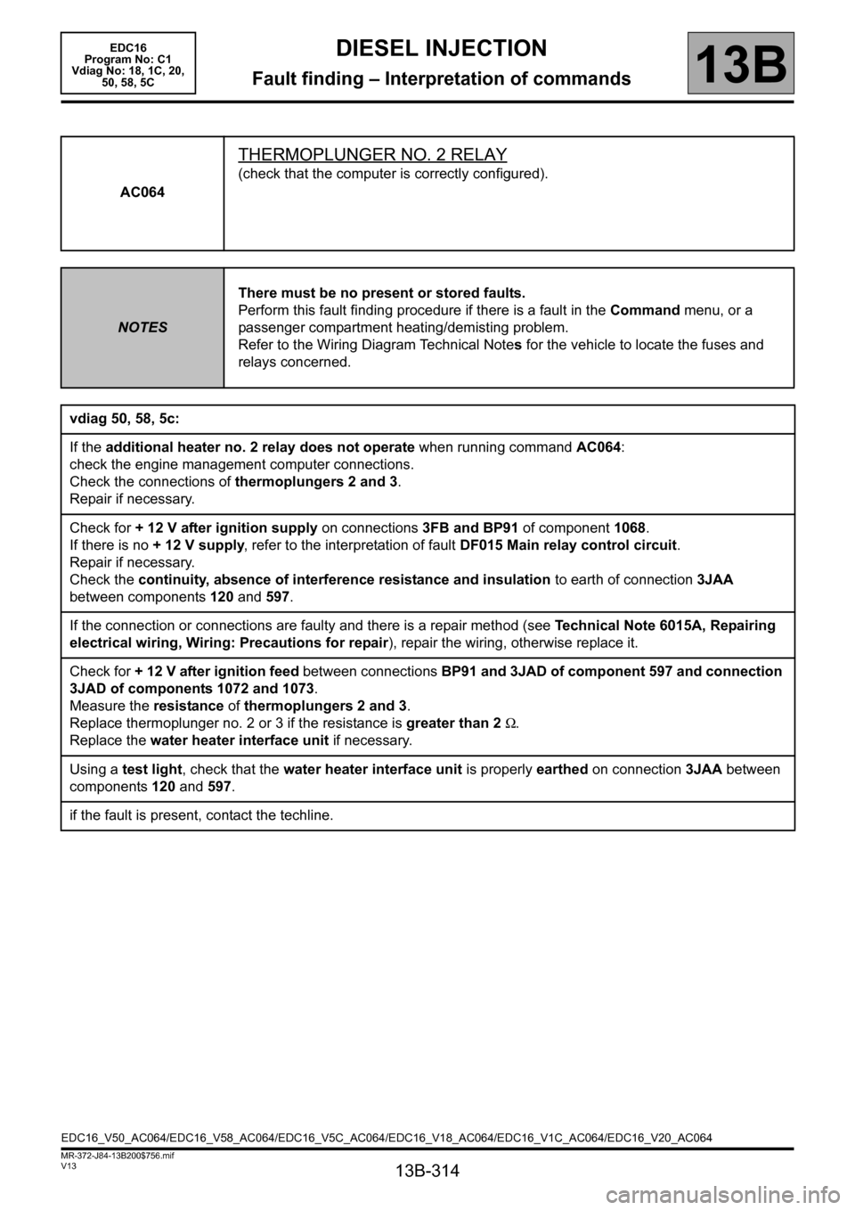
AC064
THERMOPLUNGER NO. 2 RELAY
(check that the computer is correctly configured).
NOTESThere must be no present or stored faults.
Perform this fault finding procedure if there is a fault in the Command menu, or a
passenger compartment heating/demisting problem.
Refer to the Wiring Diagram Technical Notes for the vehicle to locate the fuses and
relays concerned.
vdiag 50, 58, 5c:
If the additional heater no. 2 relay does not operate when running command AC064:
check the engine management computer connections.
Check the connections of thermoplungers 2 and 3.
Repair if necessary.
Check for + 12 V after ignition supply on connections 3FB and BP91 of component 1068.
If there is no + 12 V supply, refer to the interpretation of fault DF015 Main relay control circuit.
Repair if necessary.
Check the continuity, absence of interference resistance and insulation to earth of connection 3JAA
between components 120 and 597.
If the connection or connections are faulty and there is a repair method (see Technical Note 6015A, Repairing
electrical wiring, Wiring: Precautions for repair), repair the wiring, otherwise replace it.
Check for + 12 V after ignition feed between connections BP91 and 3JAD of component 597 and connection
3JAD of components 1072 and 1073.
Measure the resistance of thermoplungers 2 and 3.
Replace thermoplunger no. 2 or 3 if the resistance is greater than 2 Ω.
Replace the water heater interface unit if necessary.
Using a test light, check that the water heater interface unit is properly earthed on connection 3JAA between
components 120 and 597.
if the fault is present, contact the techline.
EDC16_V50_AC064/EDC16_V58_AC064/EDC16_V5C_AC064/EDC16_V18_AC064/EDC16_V1C_AC064/EDC16_V20_AC064
Page 317 of 365
13B-317
MR-372-J84-13B200$792.mif
V13
13B
DIESEL INJECTION
Fault finding – Customer complaints
NOTESbefore dealing with this customer complaint, check that there are no faults, and check
the conformity (or otherwise) of the parameters and statuses using the diagnostic
tool.
if the customer complaint is not eliminated, then proceed according to the
corresponding fault finding chart.
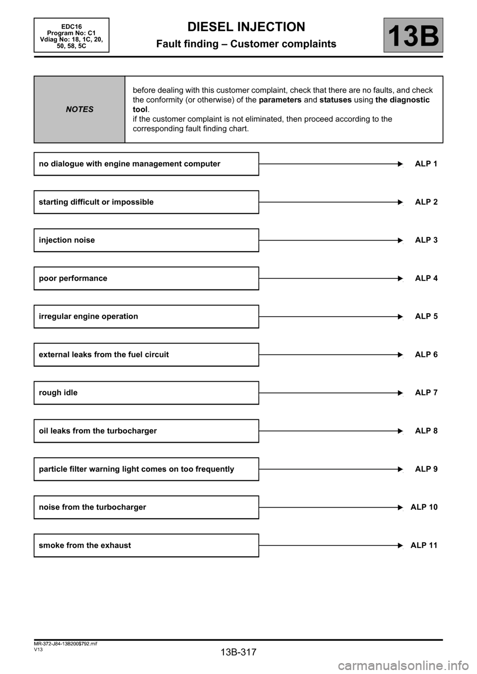
no dialogue with engine management computer ALP 1
starting difficult or impossibleALP 2
injection noiseALP 3
poor performanceALP 4
irregular engine operationALP 5
external leaks from the fuel circuit ALP 6
rough idleALP 7
oil leaks from the turbochargerALP 8
particle filter warning light comes on too frequently ALP 9
noise from the turbochargerALP 10
smoke from the exhaustALP 11
EDC16
Program No: C1
Vdiag No: 18, 1C, 20,
50, 58, 5C
MR-372-J84-13B200$792.mif
Page 320 of 365
13B-320
MR-372-J84-13B200$828.mif
V13
EDC16
Program No.: C1
Vdiag no.: 18, 1C, 20,
50, 58, 5CDIESEL INJECTION
Fault finding – Fault Finding Chart13B
ALP 2
CONTINUED 1
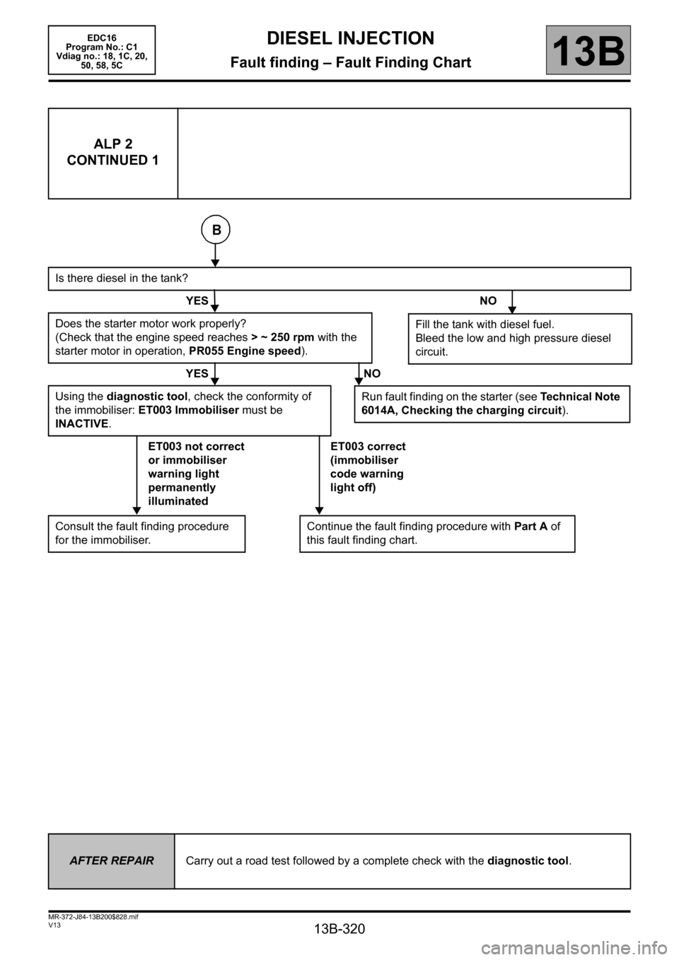
Is there diesel in the tank?
YES NO
Does the starter motor work properly?
(Check that the engine speed reaches >~250rpm with the
starter motor in operation, PR055 Engine speed).
YES NO
Using the diagnostic tool, check the conformity of
the immobiliser: ET003 Immobiliser must be
INACTIVE.
ET003 not correct
or immobiliser
warning light
permanently
illuminatedET003 correct
(immobiliser
code warning
light off)
Consult the fault finding procedure
for the immobiliser.Continue the fault finding procedure with Part A of
this fault finding chart.
Fill the tank with diesel fuel.
Bleed the low and high pressure diesel
circuit.
Run fault finding on the starter (see Technical Note
6014A, Checking the charging circuit).
AFTER REPAIRCarry out a road test followed by a complete check with the diagnostic tool.
Page 322 of 365
13B-322
MR-372-J84-13B200$828.mif
V13
EDC16
Program No.: C1
Vdiag no.: 18, 1C, 20,
50, 58, 5CDIESEL INJECTION
Fault finding – Fault Finding Chart13B
ALP 4 Poor performance
NOTESBefore dealing with this customer complaint, check that there are no faults, and
the conformity (or otherwise) of the parameters and statuses using the
diagnostic tool.
If the customer complaint is not eliminated, perform the following checks.
IMPORTANT
In the event of the engine overheating above 119°C, the computer deliberately limits the fuel flow (warning light is
illuminated when temperature exceeds 115 ° C).
Please observe the cleanliness guidelines and safety advice.
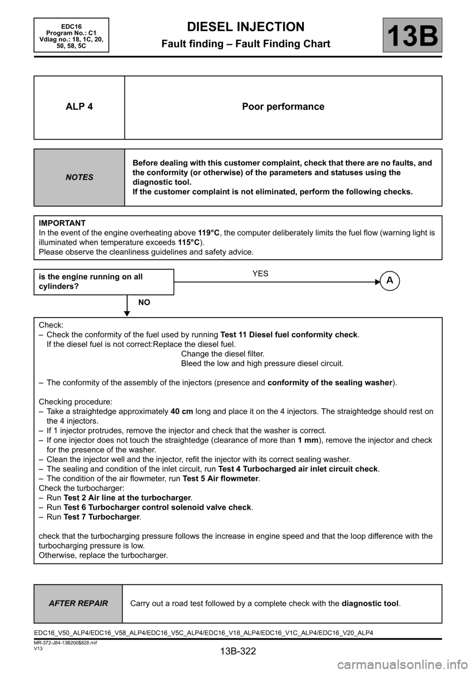
is the engine running on all
cylinders?
NO
Check:
– Check the conformity of the fuel used by running Test 11 Diesel fuel conformity check.
If the diesel fuel is not correct:Replace the diesel fuel.
Change the diesel filter.
Bleed the low and high pressure diesel circuit.
– The conformity of the assembly of the injectors (presence and conformity of the sealing washer).
Checking procedure:
– Take a straightedge approximately 40 cm long and place it on the 4 injectors. The straightedge should rest on
the 4 injectors.
– If 1 injector protrudes, remove the injector and check that the washer is correct.
– If one injector does not touch the straightedge (clearance of more than 1 mm), remove the injector and check
for the presence of the washer.
– Clean the injector well and the injector, refit the injector with its correct sealing washer.
– The sealing and condition of the inlet circuit, run Test 4 Turbocharged air inlet circuit check.
– The condition of the air flowmeter, run Test 5 Air flowmeter.
Check the turbocharger:
–Run Test 2 Air line at the turbocharger.
–Run Test 6 Turbocharger control solenoid valve check.
–Run Test 7 Turbocharger.
check that the turbocharging pressure follows the increase in engine speed and that the loop difference with the
turbocharging pressure is low.
Otherwise, replace the turbocharger.
YES
AFTER REPAIRCarry out a road test followed by a complete check with the diagnostic tool.
EDC16_V50_ALP4/EDC16_V58_ALP4/EDC16_V5C_ALP4/EDC16_V18_ALP4/EDC16_V1C_ALP4/EDC16_V20_ALP4
Page 331 of 365
13B-331
MR-372-J84-13B200$828.mif
V13
EDC16
Program No.: C1
Vdiag no.: 18, 1C, 20,
50, 58, 5CDIESEL INJECTION
Fault finding – Fault Finding Chart13B
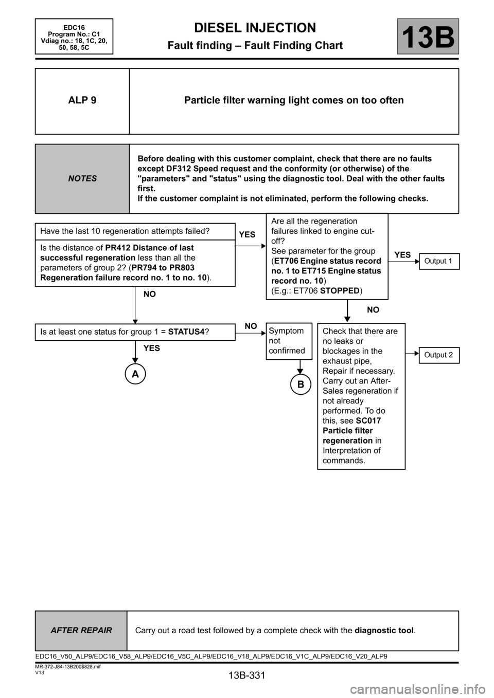
ALP 9 Particle filter warning light comes on too often
NOTESBefore dealing with this customer complaint, check that there are no faults
except DF312 Speed request and the conformity (or otherwise) of the
"parameters" and "status" using the diagnostic tool. Deal with the other faults
first.
If the customer complaint is not eliminated, perform the following checks.
Have the last 10 regeneration attempts failed?
Is the distance of PR412 Distance of last
successful regeneration less than all the
parameters of group 2? (PR794 to PR803
Regeneration failure record no. 1 to no. 10).
NO
Is at least one status for group 1 = STATUS4?
YES
YESAre all the regeneration
failures linked to engine cut-
off?
See parameter for the group
(ET706 Engine status record
no. 1 to ET715 Engine status
record no. 10)
(E.g.: ET706 STOPPED)
NO
Symptom
not
confirmed
YESOutput 1
NO
Check that there are
no leaks or
blockages in the
exhaust pipe,
Repair if necessary.
Carry out an After-
Sales regeneration if
not already
performed. To do
this, see SC017
Particle filter
regeneration in
Interpretation of
commands.
Output 2
AFTER REPAIRCarry out a road test followed by a complete check with the diagnostic tool.
EDC16_V50_ALP9/EDC16_V58_ALP9/EDC16_V5C_ALP9/EDC16_V18_ALP9/EDC16_V1C_ALP9/EDC16_V20_ALP9
A
B
Page 335 of 365
13B-335
MR-372-J84-13B200$828.mif
V13
DIESEL INJECTION
Fault finding – Fault Finding Chart
EDC16
Program No.: C1
Vdiag no.: 18, 1C, 20,
50, 58, 5C
13B
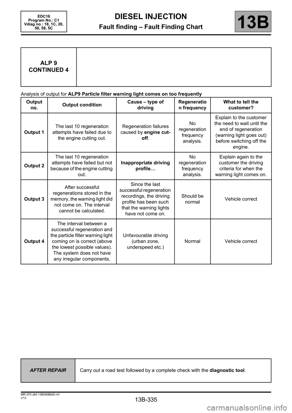
Analysis of output for ALP9 Particle filter warning light comes on too frequently
ALP 9
CONTINUED 4
Output
no. Output conditionCause – type of
drivingRegeneratio
n frequencyWhat to tell the
customer?
Output 1The last 10 regeneration
attempts have failed due to
the engine cutting out.Regeneration failures
caused by engine cut-
off.No
regeneration
frequency
analysis.Explain to the customer
the need to wait until the
end of regeneration
(warning light goes out)
before switching off the
engine.
Output 2The last 10 regeneration
attempts have failed but not
because of the engine cutting
out.Inappropriate driving
profile…No
regeneration
frequency
analysis.Explain again to the
customer the driving
criteria for when the
warning light comes on.
Output 3After successful
regenerations stored in the
memory, the warning light did
not come on. The interval
cannot be calculated.Since the last
successful regeneration
recordings, the driving
profile has been such
that the warning lights
have not come on.Should be
normalVehicle correct
Output 4The interval between a
successful regeneration and
the particle filter warning light
coming on is correct (above
the lowest possible values).
The system does not have
any irregular components.Unfavourable driving
(urban zone,
underspeed etc.)Normal Vehicle correct
AFTER REPAIRCarry out a road test followed by a complete check with the diagnostic tool.