Diagram RENAULT SCENIC 2011 J95 / 3.G Engine And Peripherals EDC16C36 Workshop Manual
[x] Cancel search | Manufacturer: RENAULT, Model Year: 2011, Model line: SCENIC, Model: RENAULT SCENIC 2011 J95 / 3.GPages: 431, PDF Size: 2.03 MB
Page 199 of 431

13B-199
AFTER REPAIRDeal with any other faults. Clear the fault memory.
Switch off the ignition until the end of the power-latch phase, and carry out a road test
followed by a check using the diagnostic tool.
V9 MR-372-J84-13B450$104.mif
DIESEL INJECTION
Fault finding – Interpretation of faults13B
DF970
CONTINUED
Check the condition of the connector of the richness ratio sensor (see Wiring Diagram Technical Note, Mégane
II ph2, Scénic II ph2, Component code 1587).
Check the condition of the connector of the engine management computer (see Wiring Diagram Technical Note,
Mégane II ph2, Scénic II ph2, Component code 120).
If the connector or connectors are faulty and if there is a repair procedure (see Technical Note 6015A, Repairing
electrical wiring, Wiring: Precautions for repair), repair the connector, otherwise replace the wiring.
Check the continuity, insulation and absence of interference resistance on the following connections:
– Connection code 3AAS between components 1587 and 120.
– Connection code 3AAT between components 1587 and 120.
– Connection code 3AAU between components 1587 and 120.
– Connection code 3AAV between components 1587 and 120.
– Connection code 3AAW between components 1587 and 120.
Check for + 12 V on the connector of the richness ratio sensor.
– Connection code 3FB of component 1587.
If there is a repair method (see Technical Note 6015A, Repairing electrical wiring, Wiring: Precautions for
repair), repair the wiring, otherwise replace it.
If the fault is still present, contact the Techline.
EDC16 C36
Program No.: 91
Vdiag No.: 44, 4C, 48
Page 200 of 431

13B-200
AFTER REPAIRDeal with any other faults. Clear the fault memory.
Switch off the ignition until the end of the power-latch phase, and carry out a road test
followed by a check using the diagnostic tool.
V9 MR-372-J84-13B450$104.mif
DIESEL INJECTION
Fault finding – Interpretation of faults13B
DF980
PRESENT
OR
STOREDRICHNESS RATIO SENSOR FUNCTION
1.DEF: Above max threshold
2.DEF: Below minimum threshold
3.DEF: Signal incoherence
NOTESConditions for applying the fault finding procedure to a stored fault:
The fault is declared present after the ignition has been switched on.
Special notes:
Use the bornier Elé. 1681 for all operations on the connectors of the injection
computer.
The richness ratio sensor is only present on certain F9Q818 engines. Check that the
vehicle is correctly equipped with this sensor.
Use Wiring Diagram Technical Note, Mégane II ph2, Scénic II ph2.
Check the condition of the connector of the richness ratio sensor (see Wiring Diagram Technical Note, Mégane
II ph2, Scénic II ph2, Component code 1587).
Check the condition of the connector of the engine management computer (see Wiring Diagram Technical Note,
Mégane II ph2, Scénic II ph2, Component code 120).
If the connector or connectors are faulty and if there is a repair procedure (see Technical Note 6015A, Repairing
electrical wiring, Wiring: Precautions for repair), repair the connector, otherwise replace the wiring.
Check the continuity, insulation and absence of interference resistance on the following connections:
– Connection code 3AAS between components 1587 and 120.
– Connection code 3AAT between components 1587 and 120.
– Connection code 3AAU between components 1587 and 120.
– Connection code 3AAV between components 1587 and 120.
– Connection code 3AAW between components 1587 and 120.
Check for + 12 V on the connector of the richness ratio sensor.
– Connection code 3FB of component 1587.
If there is a repair method (see Technical Note 6015A, Repairing electrical wiring, Wiring: Precautions for
repair), repair the wiring, otherwise replace it.
If the fault is still present, contact the Techline.
EDC16C36_V44_DF980/EDC16C36_V4C_DF980/EDC16C36_V48_DF980EDC16 C36
Program No.: 91
Vdiag No.: 44, 4C, 48
Page 201 of 431
13B-201
AFTER REPAIRDeal with any other faults. Clear the fault memory.
Switch off the ignition until the end of the power-latch phase, and carry out a road test
followed by a check using the diagnostic tool.
V9 MR-372-J84-13B450$104.mif
DIESEL INJECTION
Fault finding – Interpretation of faults13B
*ADAC: Trip Computer
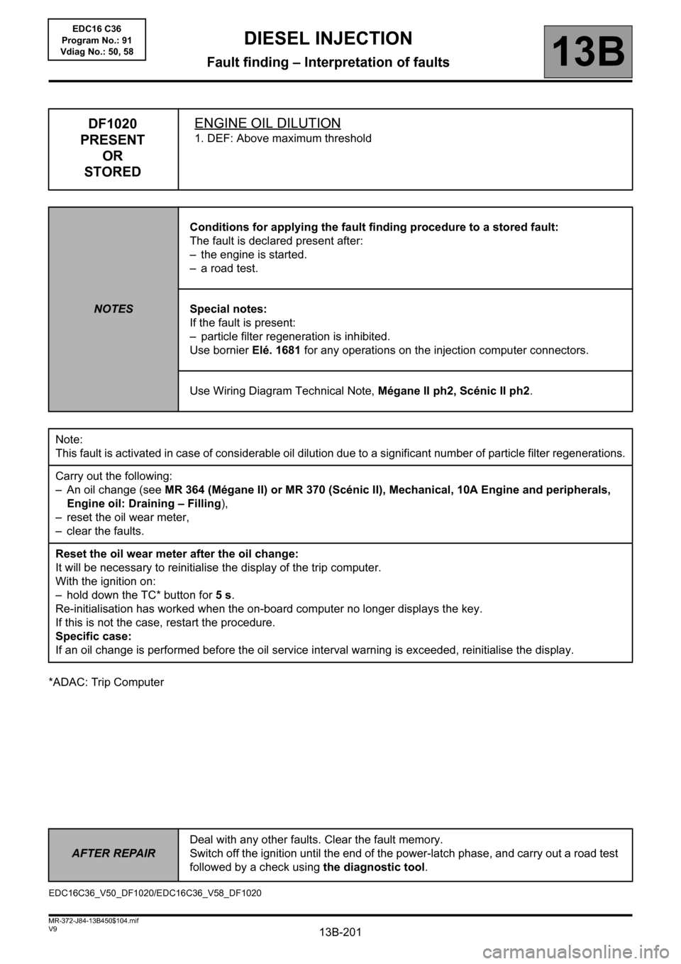
DF1020
PRESENT
OR
STOREDENGINE OIL DILUTION
1. DEF: Above maximum threshold
NOTESConditions for applying the fault finding procedure to a stored fault:
The fault is declared present after:
– the engine is started.
– a road test.
Special notes:
If the fault is present:
– particle filter regeneration is inhibited.
Use bornier Elé. 1681 for any operations on the injection computer connectors.
Use Wiring Diagram Technical Note, Mégane II ph2, Scénic II ph2.
Note:
This fault is activated in case of considerable oil dilution due to a significant number of particle filter regenerations.
Carry out the following:
– An oil change (see MR 364 (Mégane II) or MR 370 (Scénic II), Mechanical, 10A Engine and peripherals,
Engine oil: Draining – Filling),
– reset the oil wear meter,
– clear the faults.
Reset the oil wear meter after the oil change:
It will be necessary to reinitialise the display of the trip computer.
With the ignition on:
– hold down the TC* button for 5 s.
Re-initialisation has worked when the on-board computer no longer displays the key.
If this is not the case, restart the procedure.
Specific case:
If an oil change is performed before the oil service interval warning is exceeded, reinitialise the display.
EDC16C36_V50_DF1020/EDC16C36_V58_DF1020EDC16 C36
Program No.: 91
Vdiag No.: 50, 58
Page 205 of 431
13B-205V9 MR-372-J84-13B450$131.mif
13B
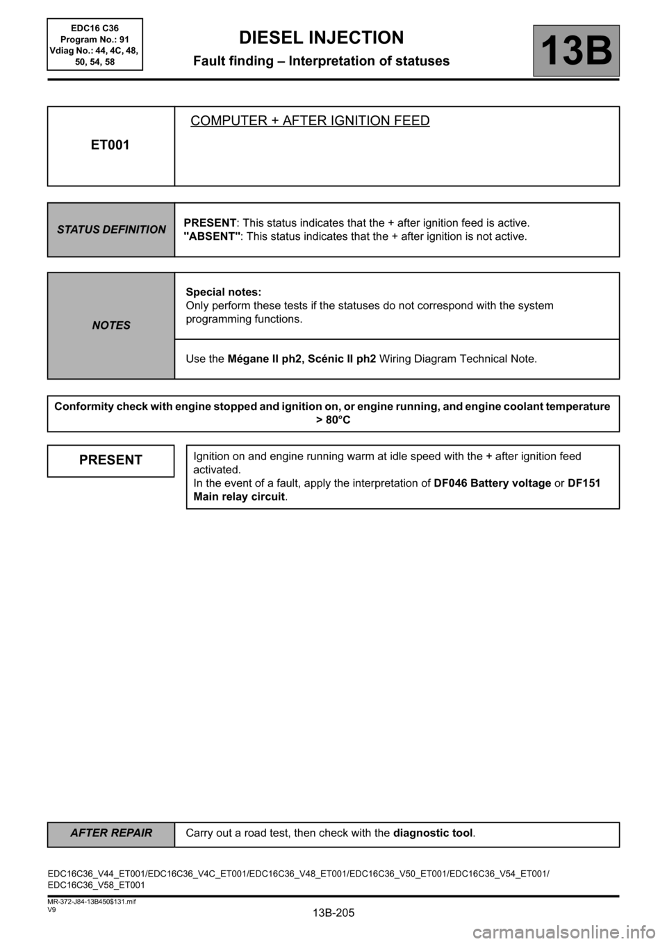
ET001COMPUTER + AFTER IGNITION FEED
STATUS DEFINITIONPRESENT: This status indicates that the + after ignition feed is active.
"ABSENT": This status indicates that the + after ignition is not active.
NOTESSpecial notes:
Only perform these tests if the statuses do not correspond with the system
programming functions.
Use the Mégane II ph2, Scénic II ph2 Wiring Diagram Technical Note.
Conformity check with engine stopped and ignition on, or engine running, and engine coolant temperature
> 80°C
PRESENTIgnition on and engine running warm at idle speed with the + after ignition feed
activated.
In the event of a fault, apply the interpretation of DF046 Battery voltage or DF151
Main relay circuit.
EDC16C36_V44_ET001/EDC16C36_V4C_ET001/EDC16C36_V48_ET001/EDC16C36_V50_ET001/EDC16C36_V54_ET001/
EDC16C36_V58_ET001
DIESEL INJECTION
Fault finding – Interpretation of statuses
AFTER REPAIRCarry out a road test, then check with the diagnostic tool.
EDC16 C36
Program No.: 91
Vdiag No.: 44, 4C, 48,
50, 54, 58
Page 206 of 431
13B-206V9 MR-372-J84-13B450$131.mif
DIESEL INJECTION
Fault finding – Interpretation of statuses13B
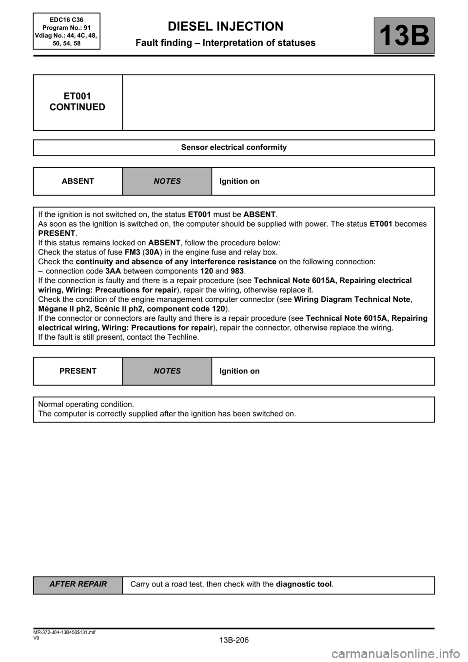
ET001
CONTINUED
Sensor electrical conformity
ABSENT
NOTESIgnition on
If the ignition is not switched on, the status ET001 must be ABSENT.
As soon as the ignition is switched on, the computer should be supplied with power. The status ET001 becomes
PRESENT.
If this status remains locked on ABSENT, follow the procedure below:
Check the status of fuse FM3 (30A) in the engine fuse and relay box.
Check the continuity and absence of any interference resistance on the following connection:
– connection code 3AA between components 120 and 983.
If the connection is faulty and there is a repair procedure (see Technical Note 6015A, Repairing electrical
wiring, Wiring: Precautions for repair), repair the wiring, otherwise replace it.
Check the condition of the engine management computer connector (see Wiring Diagram Technical Note,
Mégane II ph2, Scénic II ph2, component code 120).
If the connector or connectors are faulty and there is a repair procedure (see Technical Note 6015A, Repairing
electrical wiring, Wiring: Precautions for repair), repair the connector, otherwise replace the wiring.
If the fault is still present, contact the Techline.
PRESENT
NOTESIgnition on
Normal operating condition.
The computer is correctly supplied after the ignition has been switched on.
AFTER REPAIRCarry out a road test, then check with the diagnostic tool.
EDC16 C36
Program No.: 91
Vdiag No.: 44, 4C, 48,
50, 54, 58
Page 210 of 431
13B-210V9 MR-372-J84-13B450$131.mif
DIESEL INJECTION
Fault finding – Interpretation of statuses13B
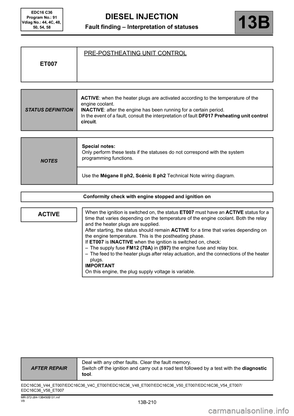
ET007PRE-POSTHEATING UNIT CONTROL
STATUS DEFINITIONACTIVE: when the heater plugs are activated according to the temperature of the
engine coolant.
INACTIVE: after the engine has been running for a certain period.
In the event of a fault, consult the interpretation of fault DF017 Preheating unit control
circuit.
NOTESSpecial notes:
Only perform these tests if the statuses do not correspond with the system
programming functions.
Use the Mégane II ph2, Scénic II ph2 Technical Note wiring diagram.
Conformity check with engine stopped and ignition on
ACTIVEWhen the ignition is switched on, the status ET007 must have an ACTIVE status for a
time that varies depending on the temperature of the engine coolant. Both the relay
and the heater plugs are supplied.
After starting, the status should remain ACTIVE for a time that varies depending on
the engine temperature. This is the postheating phase.
If ET007 is INACTIVE when the ignition is switched on, check:
– The supply fuse FM12 (70A) in (597) the engine fuse and relay box.
– The feed to the heater plugs after relay actuation, and the connections of the heater
plugs.
IMPORTANT
On this engine, the plug supply voltage is variable.
EDC16C36_V44_ET007/EDC16C36_V4C_ET007/EDC16C36_V48_ET007/EDC16C36_V50_ET007/EDC16C36_V54_ET007/
EDC16C36_V58_ET007
AFTER REPAIRDeal with any other faults. Clear the fault memory.
Switch off the ignition and carry out a road test followed by a test with the diagnostic
tool.
EDC16 C36
Program No.: 91
Vdiag No.: 44, 4C, 48,
50, 54, 58
Page 211 of 431

13B-211V9 MR-372-J84-13B450$131.mif
DIESEL INJECTION
Fault finding – Interpretation of statuses13B
ET007
CONTINUED
ACTIVE
The continuity and absence of interference resistance on the following
connections:
– Connection code 37AB between components 257 and 683,
– Connection code 37AA between components 257 and 680,
– Connection code 37Z between components 257 and 681,
– Connection code 37AC between components 257 and 682.
If the connection or connections are faulty and there is a repair procedure (see
Technical Note 6015A, Electrical wiring repair, Wiring: Precautions for repair),
repair the wiring. Otherwise replace the wiring.
Check the status of the preheating unit and that they are connected correctly (see
Wiring Diagram Technical Note, Mégane II ph2, Scénic II ph2, Component code
257).
If the connector or connectors are faulty and if there is a repair procedure (see
Technical Note 6015A, Repairing electrical wiring, Wiring: Precautions for
repair), repair the connector. Otherwise replace the wiring.
If the vehicle starts, postheating has ended and status ET007 remains ACTIVE during
the engine operating phase, consult the interpretation of faults DF017 'Preheating
unit control circuit'' and DF025 Preheating unit diagnostic line (see
Interpretation of faults).
INACTIVEIf the vehicle does not start, the status remains INACTIVE and preheating was not
executed when the ignition was switched on or during the starting phase.
Check the continuity and absence of interference resistance on the following
connections:
– Connection code 3FY, between components 120 and 257.
– Connection code 3FF between components 120 and 257.
Check the + 12 V battery supply to the pre-postheating unit.
– Connection code BP35 of component 257.
If the connection or connections are faulty and there is a repair procedure (see
Technical Note 6015A, Electrical wiring repair, Wiring: Precautions for repair),
repair the wiring. Otherwise replace the wiring.
Conformity check with engine running, engine coolant temperature > 80°C
ACTIVE
then
INACTIVEAfter the engine has been running for a certain period, the status changes from
ACTIVE to INACTIVE.
In the event of a fault, consult the interpretation of fault DF017 Preheating unit
control circuit.
AFTER REPAIRDeal with any other faults. Clear the fault memory.
Switch off the ignition and carry out a road test followed by a test with the diagnostic
tool.
EDC16 C36
Program No.: 91
Vdiag No.: 44, 4C, 48,
50, 54, 58
Page 217 of 431
13B-217V9 MR-372-J84-13B450$131.mif
DIESEL INJECTION
Fault finding – Interpretation of statuses13B
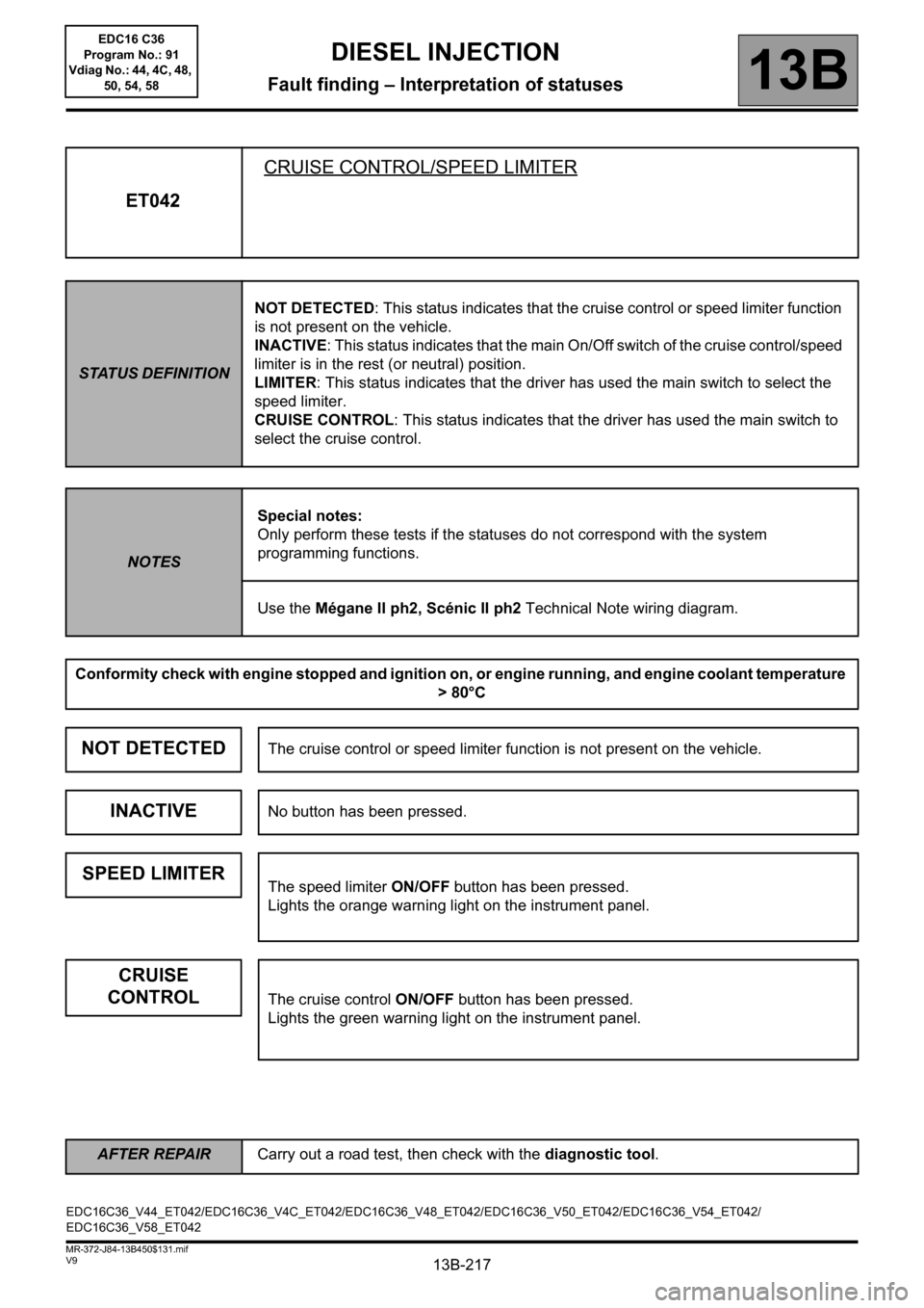
ET042CRUISE CONTROL/SPEED LIMITER
STATUS DEFINITIONNOT DETECTED: This status indicates that the cruise control or speed limiter function
is not present on the vehicle.
INACTIVE: This status indicates that the main On/Off switch of the cruise control/speed
limiter is in the rest (or neutral) position.
LIMITER: This status indicates that the driver has used the main switch to select the
speed limiter.
CRUISE CONTROL: This status indicates that the driver has used the main switch to
select the cruise control.
NOTESSpecial notes:
Only perform these tests if the statuses do not correspond with the system
programming functions.
Use the Mégane II ph2, Scénic II ph2 Technical Note wiring diagram.
Conformity check with engine stopped and ignition on, or engine running, and engine coolant temperature
> 80°C
NOT DETECTEDThe cruise control or speed limiter function is not present on the vehicle.
INACTIVENo button has been pressed.
SPEED LIMITERThe speed limiter ON/OFF button has been pressed.
Lights the orange warning light on the instrument panel.
CRUISE
CONTROL
The cruise control ON/OFF button has been pressed.
Lights the green warning light on the instrument panel.
EDC16C36_V44_ET042/EDC16C36_V4C_ET042/EDC16C36_V48_ET042/EDC16C36_V50_ET042/EDC16C36_V54_ET042/
EDC16C36_V58_ET042
AFTER REPAIRCarry out a road test, then check with the diagnostic tool.
EDC16 C36
Program No.: 91
Vdiag No.: 44, 4C, 48,
50, 54, 58
Page 230 of 431
13B-230V9 MR-372-J84-13B450$131.mif
DIESEL INJECTION
Fault finding – Interpretation of statuses13B
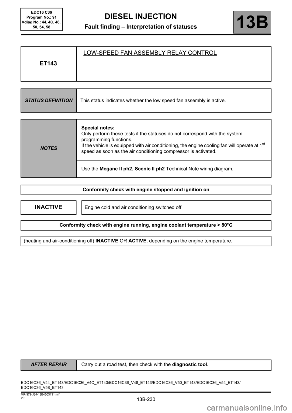
ET143LOW-SPEED FAN ASSEMBLY RELAY CONTROL
STATUS DEFINITIONThis status indicates whether the low speed fan assembly is active.
NOTESSpecial notes:
Only perform these tests if the statuses do not correspond with the system
programming functions.
If the vehicle is equipped with air conditioning, the engine cooling fan will operate at 1st
speed as soon as the air conditioning compressor is activated.
Use the Mégane II ph2, Scénic II ph2 Technical Note wiring diagram.
Conformity check with engine stopped and ignition on
INACTIVEEngine cold and air conditioning switched off
Conformity check with engine running, engine coolant temperature > 80°C
(heating and air-conditioning off) INACTIVE OR ACTIVE, depending on the engine temperature.
EDC16C36_V44_ET143/EDC16C36_V4C_ET143/EDC16C36_V48_ET143/EDC16C36_V50_ET143/EDC16C36_V54_ET143/
EDC16C36_V58_ET143
AFTER REPAIRCarry out a road test, then check with the diagnostic tool.
EDC16 C36
Program No.: 91
Vdiag No.: 44, 4C, 48,
50, 54, 58
Page 231 of 431

13B-231V9 MR-372-J84-13B450$131.mif
DIESEL INJECTION
Fault finding – Interpretation of statuses13B
ET143
CONTINUED
Sensor electrical conformity
ACTIVEWhen the coolant reaches 99°C, the injection computer commands the low-speed
relay of the fan assembly, and status ET143 becomes ACTIVE. The relay then
supplies the fan assembly and the cooling fan begins to turn.
If status ET143 is ACTIVE, but the cooling fan is not running, perform the following
operations:
– Check the condition of fuse FM15 (60 A) in the engine fuse and relay box.
Disconnect the low speed and high speed relays, check their operation and the status
of the connectors of the relay mounting (see Wiring Diagram Technical Note,
Mégane II ph2, Scénic II ph2, Component code 597).
If the connector or connectors are faulty and if there is a repair procedure (see
Technical Note 6015A, Repairing electrical wiring, Wiring: Precautions for
repair), repair the connector. Otherwise replace the wiring.
Check for the supply of + 12 V after the relay to the low-speed relay of the fan
assembly:
– Connection 3FB of component 700.
Check the continuity and the absence of interference resistance on the following
connection:
– Connection code 49L between components 700 and 321.
Check the continuity and the absence of interference resistance on the following
connection:
– Connection code 49B between components 262 and 321.
Check the continuity and the absence of interference resistance on the following
connection:
– Connection code 3JN between components 700 and 120.
Check that the earth is in order on the MAS connection of component 262.
If the connection or connections are faulty and there is a repair procedure (see
Technical Note 6015A, Electrical wiring repair, Wiring: Precautions for repair),
repair the wiring. Otherwise replace the wiring.
INACTIVEIf the engine temperature is lower than 99°C, the engine cooling fan cannot switch on
and the low speed fan relay of the cannot be run.
Status ET143 must therefore be INACTIVE when the control relay and the engine
cooling fan are not supplied.
AFTER REPAIRCarry out a road test, then check with the diagnostic tool.
EDC16 C36
Program No.: 91
Vdiag No.: 44, 4C, 48,
50, 54, 58