sensor RENAULT SCENIC 2011 J95 / 3.G Engine And Peripherals EDC16C36 Workshop Manual
[x] Cancel search | Manufacturer: RENAULT, Model Year: 2011, Model line: SCENIC, Model: RENAULT SCENIC 2011 J95 / 3.GPages: 431, PDF Size: 2.03 MB
Page 239 of 431

13B-239V9 MR-372-J84-13B450$131.mif
DIESEL INJECTION
Fault finding – Interpretation of statuses13B
ET405
CONTINUED
Sensor electrical conformity
INACTIVECheck the condition and fitting of the clutch pedal switch.
Remove the clutch pedal switch, check the insulation between connections M and
86D of component 675, with the switch in the rest position.
– Repeat this operation with the switch engaged, and check the continuity between
the two connections.
If these 2 checks are faulty, replace the switch.
Then check the continuity and absence of interference resistance of the following
connection:
– connection code 86D between components 120 and 675.
Make sure that the earth is compliant on connection M of component 675.
If the connection or connections are faulty and there is a repair procedure (see
Technical Note 6015A, Electrical wiring repair, Wiring: Precautions for repair),
repair the wiring. Otherwise replace the wiring.
ACTIVECheck the condition and fitting of the clutch pedal switch.
Remove the clutch pedal switch, check the insulation between connections M and
86D of component 675, with the switch in the rest position.
– Repeat this operation with the switch pressed, and check the continuity between the
two connections.
If these 2 checks are faulty, replace the switch.
AFTER REPAIRCarry out a road test, then check with the diagnostic tool.
EDC16 C36
Program No.: 91
Vdiag No.: 44, 4C, 48,
50, 54, 58
Page 241 of 431

13B-241V9 MR-372-J84-13B450$131.mif
DIESEL INJECTION
Fault finding – Interpretation of statuses13B
ET415
CONTINUED 1
STATUS 7
Inconsistency between the request and the vehicle speed.
STATUS 8Automatic transmission in defect mode.
STATUS 9Vehicle speed monitoring.
STATUS 10Monitoring by the injection computer.
Sensor electrical conformity
Note:
Cruise control can be activated when the vehicle speed exceeds 18 mph (30 km/h).
Status ET415 displays the various reasons for deactivation of the cruise control/speed limiter function, due to a
driver request or the external environment (e.g. STATUS 1).
IMPORTANT
Clear the fault memory by running command RZ001 Fault memory to reset this status to NONE.
WITHOUT
This status is present on the diagnostic tool if:
the computer has been reinitialised,
the computer has been reprogrammed.
AFTER REPAIRCarry out a road test, then check with the diagnostic tool.
EDC16 C36
Program No.: 91
Vdiag No.: 44, 4C, 48,
50, 54, 58
Page 250 of 431

13B-250V9 MR-372-J84-13B450$132.mif
DIESEL INJECTION
Fault finding – Interpretation of statuses13B
ET703
CONTINUED 1
DECREASE
Decrease button pressed.
In the event of a fault, consult the interpretation of status ET703.
INCREASEIncrease button pressed.
In the event of a fault, consult the interpretation of status ET703.
Sensor electrical conformity
INACTIVEStatus ET703 becomes INACTIVE when none of the cruise control/speed limiter
buttons are pressed. These buttons are located on the steering wheel.
To carry out these checks and measurements in complete safety, observe the
recommendations for removing the driver's frontal airbag (see MR 364 Mégane,
MR370 Scénic, Mechanical, 88C, Airbag and pretensioners, Driver's front
airbag, Removal - Refitting).
If status ET703 does not display INACTIVE,
– check the status of the cruise control/speed limiter +/- button and the condition of its
connector.
– check the status of the cruise control/speed limiter R/0 button and the condition of
its connector.
Repair if necessary.
INCREASEStatus ET703 becomes INCREASE when the + button of the cruise control/speed
limiter is pressed. This button is on the steering wheel, on the left-hand side.
To carry out these checks and measurements in complete safety, observe the
recommendations for removing the driver's frontal airbag (see MR 364 Mégane,
MR370 Scénic, Mechanical, 88C, Airbag and pretensioners, Driver's front
airbag, Removal - Refitting)
If status ET703 does not display INCREASE, check the status of the +/- button of the
cruise control/speed limiter and the status of its connector. Repair if necessary.
Measure the resistance on the following connections while pressing the +
button (on the button tracks):
– Connection code 86G of component 331.
– Connection code 86M of component 331.
If the resistance is not approximately 300 Ω, check the continuity of the connection
when the button is not pressed.
If there is continuity, replace the +/- control button.
AFTER REPAIRCarry out a road test, then check with the diagnostic tool.
EDC16 C36
Program No.: 91
Vdiag No.: 44, 4C, 48,
50, 54, 58
Page 254 of 431

13B-254V9 MR-372-J84-13B450$132.mif
DIESEL INJECTION
Fault finding – Interpretation of statuses13B
ET704
ET705
CONTINUED
Sensor electrical conformity
ACTIVE
or
INACTIVEIf the brake lights are working:
check the continuity and the absence of interference resistance on the following
connection:
– Connection code 5A between components 160 and 120/645/119.
If there is a repair procedure (see Technical Note 6015A, Repairing electrical
wiring, Wiring: Precautions for repair) repair the wiring, otherwise replace it.
If the brake lights are not operational, check:
– the condition and fitting of the brake switch,
– the status and conformity of the fuse for the brake lights.
– the conformity of the values in the following table:
Disconnect the switch and carry out the following checks:
for MEGANE II and SCENIC II with ESP
Continuity between
connectionsInsulation between
connections
Switch engaged
(Brake pedal released)5A and BPT 65G and SP17
Switch released
(Brake pedal
depressed)65G and SP17 5A and BPT
Replace the switch if the values obtained are not correct.
For MEGANE II and SCENIC II without ESP
Continuity between
connectionsInsulation between
connections
Switch engaged
(Brake pedal released)5A and BPT 65A and SP17
Switch released
(Brake pedal
depressed)65A and SP17 5A and BPT
Replace the switch if the values obtained are not correct.
AFTER REPAIRCarry out a road test, then check with the diagnostic tool.
EDC16 C36
Program No.: 91
Vdiag No.: 44, 4C, 48,
50, 54, 58
Page 260 of 431

13B-260V9 MR-372-J84-13B450$140.mif
DIESEL INJECTION
Fault finding – Parameter summary table13B
EDC16 C36
Program No.: 91
Vdiag No.: 44, 4C, 48,
50, 54, 58
Tool parameter Diagnostic tool title
PR076Refrigerant sensor voltage
PR077EGR valve position sensor voltage
PR079Atmospheric pressure sensor voltage
PR080Rail pressure sensor voltage
PR082Fuel temperature sensor voltage
PR083Air temperature sensor voltage
PR084Coolant temperature sensor voltage.
PR086Pedal potentiometer voltage gang 1
PR088Pedal potentiometer gang 2 voltage
PR089Vehicle speed
PR128First EGR valve offset
PR129Last EGR valve offset
PR130Cruise control setpoint
PR131EGR air flow difference
PR132Air flow
PR146Inlet air flow
PR157Fuel flow setpoint
PR171Air flow setpoint for EGR
PR190Engine idle speed setpoint.
PR209Turbocharging pressure loop difference
PR213Rail pressure loop difference
PR224Turbocharging pressure sensor voltage
PR358Sensor reference voltage
PR364Cylinder no. 1 fuel flow correction
PR365Cylinder no. 4 fuel flow correction
PR381Particle filter downstream temperature
PR382Particle filter upstream temperature
PR383Weight of soot in the particle filter
Page 261 of 431

13B-261V9 MR-372-J84-13B450$140.mif
DIESEL INJECTION
Fault finding – Parameter summary table13B
EDC16 C36
Program No.: 91
Vdiag No.: 44, 4C, 48,
50, 54, 58
* diff: differential
* temp: temperatureTool parameter Diagnostic tool title
PR385Exhaust pipe flow
PR391Mileage since particle filter replacement
PR405Cylinder no. 2 fuel flow correction
PR406Cylinder no. 3 fuel flow correction
PR412Mileage at last successful regeneration
PR414Particle filter pressure diff.*
PR415Time since last regeneration
PR420Damper valve error counter
PR667Turbine upstream temperature
PR668Turbine upstream temperature sensor voltage
PR672Damper valve position setpoint
PR747Damper valve position
PR777Richness ratio sensor voltage
PR778Richness ratio sensor temp.*
PR779Richness ratio
PR784DF312 recording No. 1
PR785DF312 recording No. 2
PR786DF312 recording No. 3
PR787DF312 recording No. 4
PR788DF312 recording No. 5
PR789DF312 recording No. 6
PR790DF312 recording No. 7
PR791DF312 recording No. 8
PR792DF312 recording No. 9
PR793DF312 recording No. 10
PR794Stored regeneration failure no. 1
PR795Stored regeneration failure no. 2
PR796Stored regeneration failure no. 3
Page 271 of 431

13B-271
AFTER REPAIRCarry out a road test, then check with the diagnostic tool.
V9 MR-372-J84-13B450$151.mif
DIESEL INJECTION
Fault finding – Interpretation of parameters13B
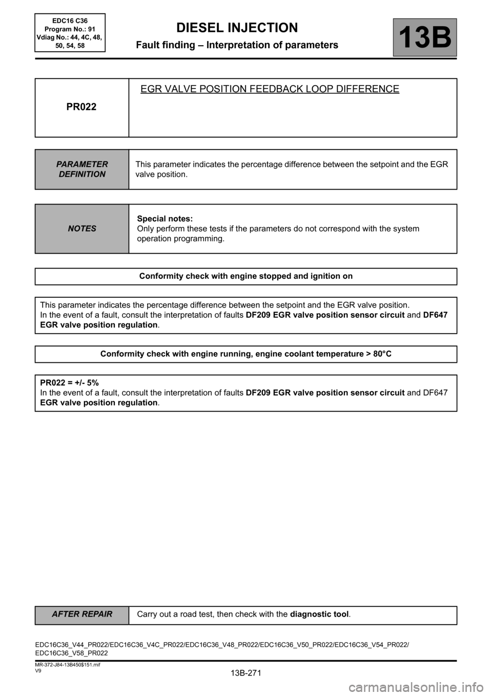
PR022EGR VALVE POSITION FEEDBACK LOOP DIFFERENCE
PARAMETER
DEFINITIONThis parameter indicates the percentage difference between the setpoint and the EGR
valve position.
NOTESSpecial notes:
Only perform these tests if the parameters do not correspond with the system
operation programming.
Conformity check with engine stopped and ignition on
This parameter indicates the percentage difference between the setpoint and the EGR valve position.
In the event of a fault, consult the interpretation of faults DF209 EGR valve position sensor circuit and DF647
EGR valve position regulation.
Conformity check with engine running, engine coolant temperature > 80°C
PR022 = +/- 5%
In the event of a fault, consult the interpretation of faults DF209 EGR valve position sensor circuit and DF647
EGR valve position regulation.
EDC16C36_V44_PR022/EDC16C36_V4C_PR022/EDC16C36_V48_PR022/EDC16C36_V50_PR022/EDC16C36_V54_PR022/
EDC16C36_V58_PR022EDC16 C36
Program No.: 91
Vdiag No.: 44, 4C, 48,
50, 54, 58
Page 272 of 431

13B-272
AFTER REPAIRCarry out a road test, then check with the diagnostic tool.
V9 MR-372-J84-13B450$151.mif
DIESEL INJECTION
Fault finding – Interpretation of parameters13B
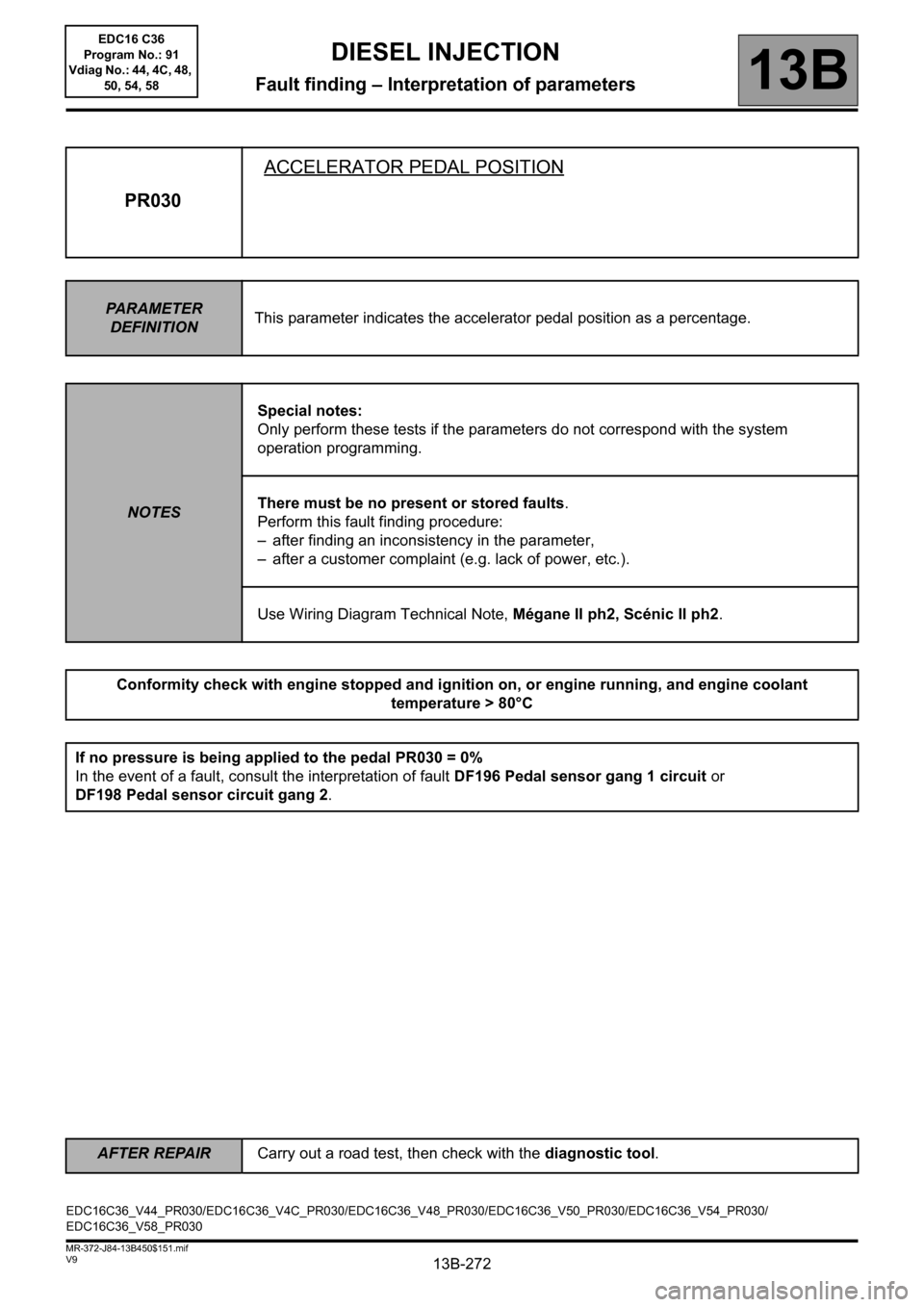
PR030ACCELERATOR PEDAL POSITION
PARAMETER
DEFINITIONThis parameter indicates the accelerator pedal position as a percentage.
NOTESSpecial notes:
Only perform these tests if the parameters do not correspond with the system
operation programming.
There must be no present or stored faults.
Perform this fault finding procedure:
– after finding an inconsistency in the parameter,
– after a customer complaint (e.g. lack of power, etc.).
Use Wiring Diagram Technical Note, Mégane II ph2, Scénic II ph2.
Conformity check with engine stopped and ignition on, or engine running, and engine coolant
temperature > 80°C
If no pressure is being applied to the pedal PR030 = 0%
In the event of a fault, consult the interpretation of fault DF196 Pedal sensor gang 1 circuit or
DF198 Pedal sensor circuit gang 2.
EDC16C36_V44_PR030/EDC16C36_V4C_PR030/EDC16C36_V48_PR030/EDC16C36_V50_PR030/EDC16C36_V54_PR030/
EDC16C36_V58_PR030EDC16 C36
Program No.: 91
Vdiag No.: 44, 4C, 48,
50, 54, 58
Page 273 of 431

13B-273
AFTER REPAIRCarry out a road test, then check with the diagnostic tool.
V9 MR-372-J84-13B450$151.mif
DIESEL INJECTION
Fault finding – Interpretation of parameters13B
PR030
CONTINUED
Sensor electrical conformity
Check the continuity and the absence of interference resistance of the following connections:
– Connection code 3LR,
– Connection code 3LS,
– Connection code 3LT,
– Connection code 3LU,
– Connection code 3LW,
– Connection code 3LV,
between components 120 and 921.
If any of the connections are faulty and there is a repair method (see Technical Note 6015A, Electrical wiring
repair, Wiring: precautions for repairs), repair the wiring; otherwise replace the wiring.
Pedal sensor connected, vehicle with the ignition on and the engine stopped:
– check that the value of PR030 Accelerator pedal position:
0% no load,
100% full load,
138% full load after kickdown point on pedal.
– if the value is not correct, replace the pedal sensor.
EDC16 C36
Program No.: 91
Vdiag No.: 44, 4C, 48,
50, 54, 58
Page 274 of 431

13B-274
AFTER REPAIRCarry out a road test, then check with the diagnostic tool.
V9 MR-372-J84-13B450$151.mif
DIESEL INJECTION
Fault finding – Interpretation of parameters13B
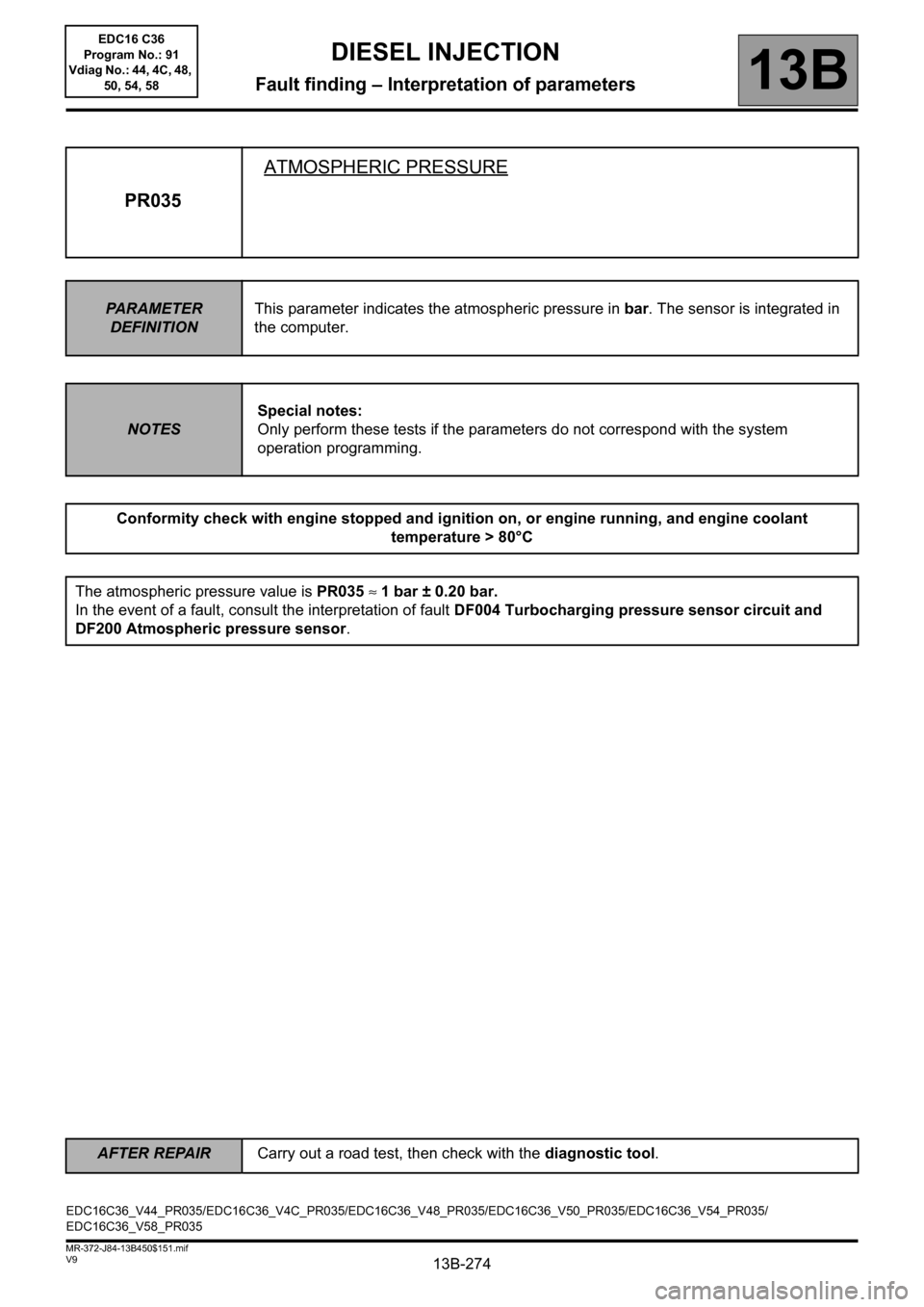
PR035ATMOSPHERIC PRESSURE
PARAMETER
DEFINITIONThis parameter indicates the atmospheric pressure in bar. The sensor is integrated in
the computer.
NOTESSpecial notes:
Only perform these tests if the parameters do not correspond with the system
operation programming.
Conformity check with engine stopped and ignition on, or engine running, and engine coolant
temperature > 80°C
The atmospheric pressure value is PR035 ≈ 1 bar ± 0.20 bar.
In the event of a fault, consult the interpretation of fault DF004 Turbocharging pressure sensor circuit and
DF200 Atmospheric pressure sensor.
EDC16C36_V44_PR035/EDC16C36_V4C_PR035/EDC16C36_V48_PR035/EDC16C36_V50_PR035/EDC16C36_V54_PR035/
EDC16C36_V58_PR035EDC16 C36
Program No.: 91
Vdiag No.: 44, 4C, 48,
50, 54, 58