wiring RENAULT SCENIC 2011 J95 / 3.G Engine And Peripherals EDC16C36 Workshop Manual
[x] Cancel search | Manufacturer: RENAULT, Model Year: 2011, Model line: SCENIC, Model: RENAULT SCENIC 2011 J95 / 3.GPages: 431, PDF Size: 2.03 MB
Page 2 of 431

13B-2V9 MR-372-J84-13B450$010.mif
13B
EDC16 C36
Program No.: 91
Vdiag No.: 44, 4C, 48,
50, 54, 58
1. SCOPE OF THIS DOCUMENT
This document presents the fault finding procedure applicable to all computers with the following specifications:
2. PREREQUISITES FOR FAULT FINDING
Documentation type
Fault finding procedures (this document):
– Assisted fault finding (integrated into the diagnostic tool), Dialogys.
Wiring Diagrams:
– Visu-Schéma (CD-ROM), paper.
Type of diagnostic tools
–CLIP
Special tooling required
3. REMINDERS
Procedure
To save energy, the vehicle's UCH interrupts the + after ignition feed after 3 minutes.
To run fault finding on a computer, it is possible to force the + after ignition feed for 1 hour by applying the following
procedure:
– press the unlocking button on the card,
– insert the card in the reader,
– press the start button (interrupting the timed + after ignition feed mode),
– press the start button for more than 5 seconds, without conditions for starting being met, until the immobiliser
warning light flashes rapidly (4 Hz).
This forced + after ignition feed mode is active for 1 hour.
Pressing the start button or removing the card from the card reader interrupts the forced + after ignition feed, but
does not interrupt the time period for the forced + after ignition feed. Until one hour has elapsed, activating the +
after ignition feed will restart forced + after ignition feed for the remaining time. Vehicle(s): MEGANE II phase 2, SCENIC II
phase 2Name of computer: BOSCH EDC16 C36
Engine: F9Q 816, 818Program No.: 91
Function concerned: DIESEL INJECTIONVdiag No.: 44, 4C, 48, 50, 54, 58
Special tooling required
Multimeter
Elé. 1681 Universal bornier
EDC16C36_V44_PRELI/EDC16C36_V4C_PRELI/EDC16C36_V48_PRELI/EDC16C36_V50_PRELI/EDC16C36_V54_PRELI/
EDC16C36_V58_PRELI
DIESEL INJECTION
Fault finding – Introduction
Page 5 of 431

13B-5V9 MR-372-J84-13B450$010.mif
DIESEL INJECTION
Fault finding – Introduction13B
EDC16 C36
Program No.: 91
Vdiag No.: 44, 4C, 48,
50, 54, 58
4. FAULT FINDING PROCEDURE (continued)
Wiring check
Fault finding problems
Disconnecting the connectors and/or manipulating the wiring may temporarily clear the cause of a fault.
Visual inspection
Look for damage under the bonnet and in the passenger compartment.
Carefully check the protectors, insulation, and routing of the wiring, as well as the mountings.
Physical inspection
When working on wiring, use the diagnostic tool to highlight a change in the status of the faults, from a "stored"
fault to a "present" fault, or use the multimeter to view the status changes.
Make sure that the connectors are firmly secured.
Apply light pressure to the connectors.
Twist the wiring harness.
Checking insulation to earth
This check is carried out by measuring the voltage (multimeter in voltmeter mode) between the suspect connection
and the 12 V or 5V. The correct measured value is 0V.
Checking insulation in relation to + 12 V or + 5 V
This check is carried out by measuring the voltage (multimeter in voltmeter mode) between the suspect connection
and the earth. In the first instance, the earth may be taken on the chassis. The correct measured value is 0V.
Continuity check
A continuity check is carried out by measuring the resistance (multimeter in ohmmeter mode), with the connectors
disconnected at both ends. The expected result is: 1 Ω ± 1 Ω for each connection. The line must be fully checked,
and the intermediate connections are only included in the method if this saves time during the fault finding
procedure. The continuity check on the multiplex lines must be carried out on both wires. The measured value
should be 1 Ω ± 1 Ω.
Power supply check
This check can be carried out using a test light (21 W or 5 W depending on the maximum permissible load).
Page 6 of 431

13B-6V9 MR-372-J84-13B450$010.mif
DIESEL INJECTION
Fault finding – Introduction13B
EDC16 C36
Program No.: 91
Vdiag No.: 44, 4C, 48,
50, 54, 58
4.1 Connector check
1. Visual inspection of the connection:
– Check that the connector is connected correctly and that the male and female parts of the connection are correctly
coupled.
2. Visual inspection of the area around the connection:
– Check the condition of the mounting (pin, strap, adhesive tape, etc.) if the connectors are attached to the vehicle.
– Check that there is no damage to the wiring trim (sheath, foam, adhesive tape, etc.) near the wiring.
– Check that there is no damage to the electrical wires at the connector outputs, in particular on the insulating material
(wear, cuts, burns, etc.).
Disconnect the connector to continue the checks.
3. Visual inspection of the plastic casing:
– Check that there is no mechanical damage (casing crushed, cracked, broken, etc.), in particular to the fragile
components (lever, lock, terminal locations, etc.).
– Check that there is no heat damage (casing melted, blackened, deformed, etc.).
– Check that there are is no dirt (grease, mud, liquid, etc.).
4. Visual inspection of the metal contacts:
(The female contact is called CLIP. The male contact is called a TAB).
– Check that there are no bent contacts (the contact is not inserted correctly and can come out of the back of the
connector). The spring contact of the connector when the wire is pulled slightly.
– Check that there is no damage (tabs bent, clips open too wide, blackened or melted, etc.).
– Check that there is no oxidation on the metal contacts. Note:
Carry out each requested check visually. Do not remove a connector if it is not required.
Note:
Repeated connections and disconnections alter the functionality of the connectors and increase the risk of a poor
electrical contact. Restrict the number of connections/disconnections as far as possible.
Note:
The check is carried out on the 2 parts of the connection. There may be 2 types of connections:
– Connector/Connector.
– Connector/Device.
Page 7 of 431
13B-7V9 MR-372-J84-13B450$010.mif
DIESEL INJECTION
Fault finding – Introduction13B
EDC16 C36
Program No.: 91
Vdiag No.: 44, 4C, 48,
50, 54, 58
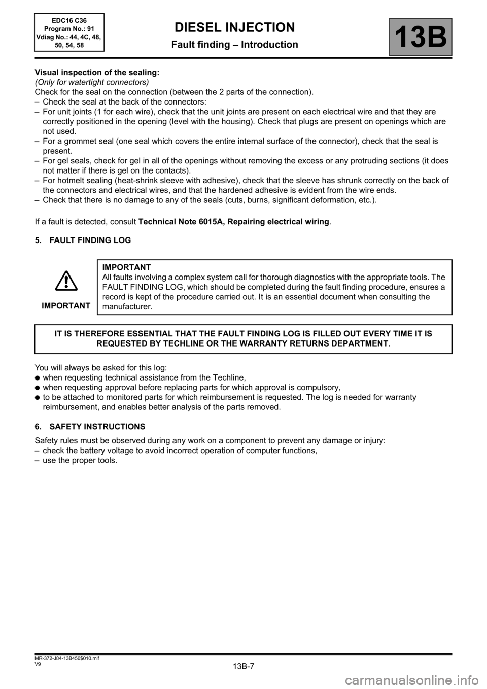
Visual inspection of the sealing:
(Only for watertight connectors)
Check for the seal on the connection (between the 2 parts of the connection).
– Check the seal at the back of the connectors:
– For unit joints (1 for each wire), check that the unit joints are present on each electrical wire and that they are
correctly positioned in the opening (level with the housing). Check that plugs are present on openings which are
not used.
– For a grommet seal (one seal which covers the entire internal surface of the connector), check that the seal is
present.
– For gel seals, check for gel in all of the openings without removing the excess or any protruding sections (it does
not matter if there is gel on the contacts).
– For hotmelt sealing (heat-shrink sleeve with adhesive), check that the sleeve has shrunk correctly on the back of
the connectors and electrical wires, and that the hardened adhesive is evident from the wire ends.
– Check that there is no damage to any of the seals (cuts, burns, significant deformation, etc.).
If a fault is detected, consult Technical Note 6015A, Repairing electrical wiring.
5. FAULT FINDING LOG
You will always be asked for this log:
●when requesting technical assistance from the Techline,
●when requesting approval before replacing parts for which approval is compulsory,
●to be attached to monitored parts for which reimbursement is requested. The log is needed for warranty
reimbursement, and enables better analysis of the parts removed.
6. SAFETY INSTRUCTIONS
Safety rules must be observed during any work on a component to prevent any damage or injury:
– check the battery voltage to avoid incorrect operation of computer functions,
– use the proper tools.IMPORTANTIMPORTANT
All faults involving a complex system call for thorough diagnostics with the appropriate tools. The
FAULT FINDING LOG, which should be completed during the fault finding procedure, ensures a
record is kept of the procedure carried out. It is an essential document when consulting the
manufacturer.
IT IS THEREFORE ESSENTIAL THAT THE FAULT FINDING LOG IS FILLED OUT EVERY TIME IT IS
REQUESTED BY TECHLINE OR THE WARRANTY RETURNS DEPARTMENT.
Page 27 of 431

13B-27V9 MR-372-J84-13B450$060.mif
DIESEL INJECTION
Fault finding – Defect modes13B
EDC16 C36
Program No.: 91
Vdiag No.: 44, 4C, 48,
50, 54, 58
* normally aspirated: naturally aspiratedDefect
modesCause of fault Customer perception
Turbocharger
cut-off– Turbocharging pressure loop difference (vanes jammed,
compressor/turbine fault, turbocharging pressure sensor fault,
sensor connection fault, functional solenoid valve fault
(disconnected, hose kinked, solenoid valve mechanism jammed),
high pressure circuit leak (high pressure hose, major distributor
leak).
– Flowmeter failure (plausibility of the reading):
– significant line resistance on earth sensor,
– significant line resistance on sensor feed, significant line resistance
on sensor signal,
– flowmeter sensing element damaged,
– wiring/connection fault,
– flowmeter voltage or 5 V reference voltage deviation.
– Flowmeter failure (plausibility of sensitivity variation):
– flowmeter clogged/flow underestimated,
– flow overestimated,
– air circuit leak between flowmeter and compressor,
– air circuit leak after compressor.
– Electrical faults:
– signal short circuit to + 12 V,
– signal short circuit to earth,
– signal open circuit,
– sensor feed open circuit,
– open circuit, short circuit to earth and turbocharger solenoid valve
short circuit to + 12 V.
– Turbocharger pressure sensor fault (sensor signal short circuit with
sensor feed, sensor signal short circuit to + 12 V, sensor open
circuit to earth, sensor signal short circuit to earth, sensor feed open
circuit, sensor signal open circuit, significant line resistance on
sensor feed, significant line resistance on sensor signal, significant
line resistance on sensor earth, significant pressure difference
measured between the atmospheric pressure sensor and the
turbocharger pressure sensor at idle speed).
– EGR valve fault (valve clogged, valve jammed open).
– Camshaft sensor fault.
– Engine speed sensor fault.
– Sensor feed No. 1 fault.25-50% loss of engine
performance (normally
aspirated engine)
Rail pressure
limited– Rail pressure sensor fault.
– Sensor feed No. 3 fault.Poor performance
Rail pressure
reduction
– Positive rail pressure loop difference (measurement < setpoint).
Poor performance
Page 40 of 431
13B-40V9 MR-372-J84-13B450$101.mif
13B
DF001
PRESENT
OR
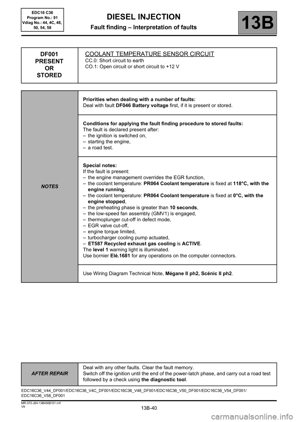
STOREDCOOLANT TEMPERATURE SENSOR CIRCUIT
CC.0: Short circuit to earth
CO.1: Open circuit or short circuit to +12 V
NOTESPriorities when dealing with a number of faults:
Deal with fault DF046 Battery voltage first, if it is present or stored.
Conditions for applying the fault finding procedure to stored faults:
The fault is declared present after:
– the ignition is switched on,
– starting the engine,
– a road test.
Special notes:
If the fault is present:
– the engine management overrides the EGR function,
– the coolant temperature: PR064 Coolant temperature is fixed at 118°C, with the
engine running,
– the coolant temperature: PR064 Coolant temperature is fixed at 0°C, with the
engine stopped,
– the preheating phase is greater than 10 seconds,
– the low-speed fan assembly (GMV1) is engaged,
– thermoplunger cut-off in defect mode,
– EGR valve cut-off,
– engine torque limited,
– turbocharger cooling pump actuated,
–ET587 Recycled exhaust gas cooling is ACTIVE.
The level 1 warning light is illuminated.
Use bornier Elé.1681 for any operations on the computer connectors.
Use Wiring Diagram Technical Note, Mégane II ph2, Scénic II ph2.
EDC16C36_V44_DF001/EDC16C36_V4C_DF001/EDC16C36_V48_DF001/EDC16C36_V50_DF001/EDC16C36_V54_DF001/
EDC16C36_V58_DF001
DIESEL INJECTION
Fault finding – Interpretation of faults
AFTER REPAIRDeal with any other faults. Clear the fault memory.
Switch off the ignition until the end of the power-latch phase, and carry out a road test
followed by a check using the diagnostic tool.
EDC16 C36
Program No.: 91
Vdiag No.: 44, 4C, 48,
50, 54, 58
Page 41 of 431
13B-41V9 MR-372-J84-13B450$101.mif
DIESEL INJECTION
Fault finding – Interpretation of faults13B
DF001
CONTINUED 1
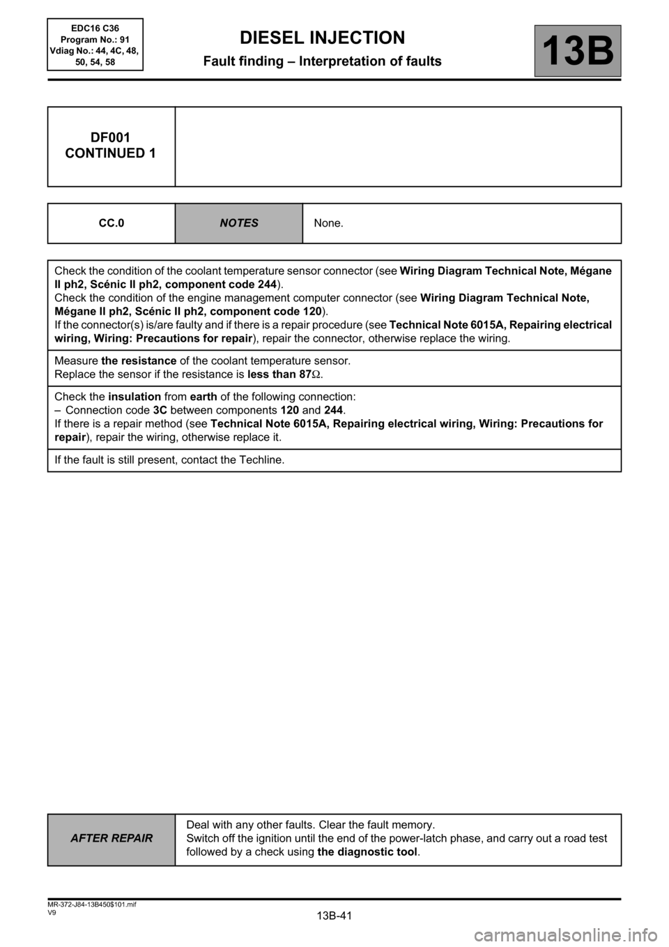
CC.0NOTESNone.
Check the condition of the coolant temperature sensor connector (see Wiring Diagram Technical Note, Mégane
II ph2, Scénic II ph2, component code 244).
Check the condition of the engine management computer connector (see Wiring Diagram Technical Note,
Mégane II ph2, Scénic II ph2, component code 120).
If the connector(s) is/are faulty and if there is a repair procedure (see Technical Note 6015A, Repairing electrical
wiring, Wiring: Precautions for repair), repair the connector, otherwise replace the wiring.
Measure the resistance of the coolant temperature sensor.
Replace the sensor if the resistance is less than 87Ω.
Check the insulation from earth of the following connection:
– Connection code 3C between components 120 and 244.
If there is a repair method (see Technical Note 6015A, Repairing electrical wiring, Wiring: Precautions for
repair), repair the wiring, otherwise replace it.
If the fault is still present, contact the Techline.
AFTER REPAIRDeal with any other faults. Clear the fault memory.
Switch off the ignition until the end of the power-latch phase, and carry out a road test
followed by a check using the diagnostic tool.
EDC16 C36
Program No.: 91
Vdiag No.: 44, 4C, 48,
50, 54, 58
Page 42 of 431
13B-42V9 MR-372-J84-13B450$101.mif
DIESEL INJECTION
Fault finding – Interpretation of faults13B
DF001
CONTINUED 2
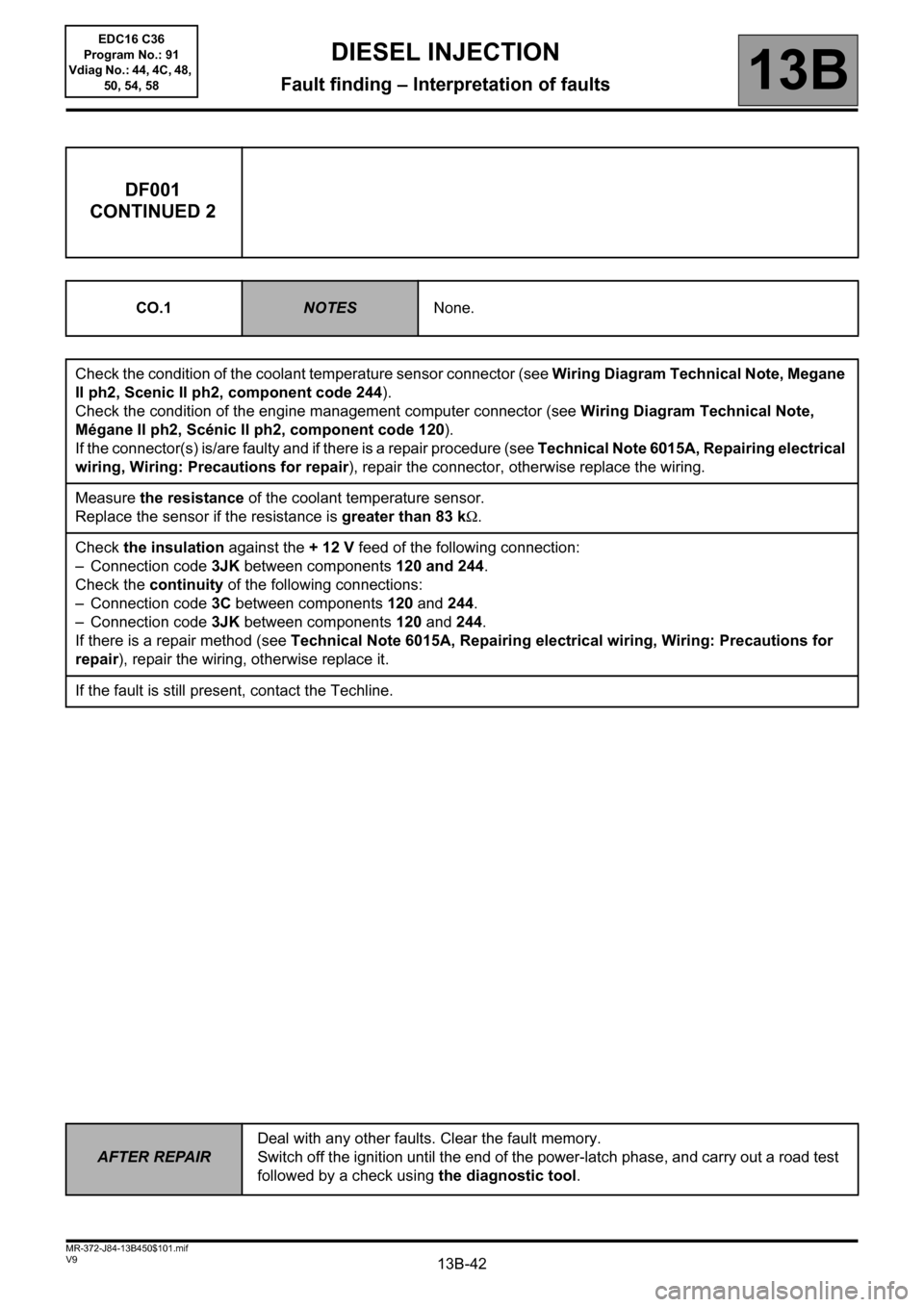
CO.1NOTESNone.
Check the condition of the coolant temperature sensor connector (see Wiring Diagram Technical Note, Megane
II ph2, Scenic II ph2, component code 244).
Check the condition of the engine management computer connector (see Wiring Diagram Technical Note,
Mégane II ph2, Scénic II ph2, component code 120).
If the connector(s) is/are faulty and if there is a repair procedure (see Technical Note 6015A, Repairing electrical
wiring, Wiring: Precautions for repair), repair the connector, otherwise replace the wiring.
Measure the resistance of the coolant temperature sensor.
Replace the sensor if the resistance is greater than 83 kΩ.
Check the insulation against the + 12 V feed of the following connection:
– Connection code 3JK between components 120 and 244.
Check the continuity of the following connections:
– Connection code 3C between components 120 and 244.
– Connection code 3JK between components 120 and 244.
If there is a repair method (see Technical Note 6015A, Repairing electrical wiring, Wiring: Precautions for
repair), repair the wiring, otherwise replace it.
If the fault is still present, contact the Techline.
AFTER REPAIRDeal with any other faults. Clear the fault memory.
Switch off the ignition until the end of the power-latch phase, and carry out a road test
followed by a check using the diagnostic tool.
EDC16 C36
Program No.: 91
Vdiag No.: 44, 4C, 48,
50, 54, 58
Page 43 of 431
13B-43V9 MR-372-J84-13B450$101.mif
DIESEL INJECTION
Fault finding – Interpretation of faults13B
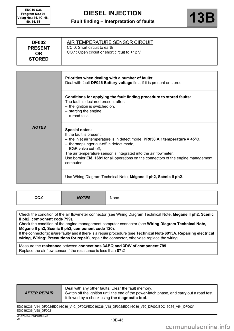
DF002
PRESENT
OR
STOREDAIR TEMPERATURE SENSOR CIRCUIT
CC.0: Short circuit to earth
CO.1: Open circuit or short circuit to +12 V
NOTESPriorities when dealing with a number of faults:
Deal with fault DF046 Battery voltage first, if it is present or stored.
Conditions for applying the fault finding procedure to stored faults:
The fault is declared present after:
– the ignition is switched on,
– starting the engine,
– a road test.
Special notes:
If the fault is present:
– the inlet air temperature is in defect mode, PR058 Air temperature =45°C.
– thermoplunger cut-off in defect mode,
– EGR valve cut-off,
The air temperature sensor is integrated into the air flowmeter.
Use bornier Elé. 1681 for all operations on the connectors of the engine management
computer.
Use Wiring Diagram Technical Note, Mégane II ph2, Scénic II ph2.
CC.0
NOTESNone.
Check the condition of the air flowmeter connector (see Wiring Diagram Technical Note, Mégane II ph2, Scenic
II ph2, component code 799).
Check the condition of the engine management computer connector (see Wiring Diagram Technical Note,
Mégane II ph2, Scénic II ph2, component code 120).
If the connector(s) is/are faulty and if there is a repair procedure (see Technical Note 6015A, Repairing electrical
wiring, Wiring: Precautions for repair), repair the connector, otherwise replace the wiring.
Measure the resistance between connections 3ABQ and 3DW of component 799.
Replace the air flow sensor if the resistance is less than 87Ω.
EDC16C36_V44_DF002/EDC16C36_V4C_DF002/EDC16C36_V48_DF002/EDC16C36_V50_DF002/EDC16C36_V54_DF002/
EDC16C36_V58_DF002
AFTER REPAIRDeal with any other faults. Clear the fault memory.
Switch off the ignition until the end of the power-latch phase, and carry out a road test
followed by a check using the diagnostic tool.
EDC16 C36
Program No.: 91
Vdiag No.: 44, 4C, 48,
50, 54, 58
Page 44 of 431
13B-44V9 MR-372-J84-13B450$101.mif
DIESEL INJECTION
Fault finding – Interpretation of faults13B
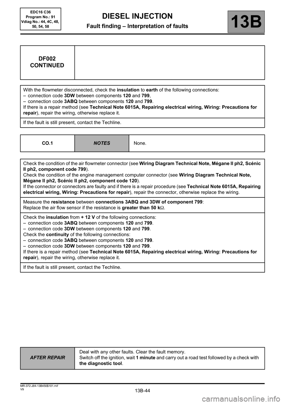
DF002
CONTINUED
With the flowmeter disconnected, check the insulation to earth of the following connections:
– connection code 3DW between components 120 and 799,
– connection code 3ABQ between components 120 and 799.
If there is a repair method (see Technical Note 6015A, Repairing electrical wiring, Wiring: Precautions for
repair), repair the wiring, otherwise replace it.
If the fault is still present, contact the Techline.
CO.1
NOTESNone.
Check the condition of the air flowmeter connector (see Wiring Diagram Technical Note, Mégane II ph2, Scénic
II ph2, component code 799).
Check the condition of the engine management computer connector (see Wiring Diagram Technical Note,
Mégane II ph2, Scénic II ph2, component code 120).
If the connector or connectors are faulty and if there is a repair procedure (see Technical Note 6015A, Repairing
electrical wiring, Wiring: Precautions for repair), repair the connector, otherwise replace the wiring.
Measure the resistance between connections 3ABQ and 3DW of component 799:
Replace the air flow sensor if the resistance is greater than 50 kΩ.
Check the insulation from + 12 V of the following connections:
– connection code 3ABQ between components 120 and 799.
– connection code 3DW between components 120 and 799.
Check the continuity of the following connections:
– connection code 3ABQ between components 120 and 799.
– connection code 3DW between components 120 and 799.
If there is a repair method (see Technical Note 6015A, Repairing electrical wiring, Wiring: Precautions for
repair), repair the wiring, otherwise replace it.
If the fault is still present, contact the Techline.
AFTER REPAIRDeal with any other faults. Clear the fault memory.
Switch off the ignition, wait 1 minute and carry out a road test followed by a check with
the diagnostic tool.
EDC16 C36
Program No.: 91
Vdiag No.: 44, 4C, 48,
50, 54, 58