engine oil RENAULT SCENIC 2011 J95 / 3.G Engine And Peripherals EDC16C36 Owner's Manual
[x] Cancel search | Manufacturer: RENAULT, Model Year: 2011, Model line: SCENIC, Model: RENAULT SCENIC 2011 J95 / 3.GPages: 431, PDF Size: 2.03 MB
Page 387 of 431
13B-387
AFTER REPAIRCarry out a road test followed by a complete check with the diagnostic tool.
V9 MR-372-J84-13B450$190.mif
DIESEL INJECTION
Fault finding – Fault Finding Chart13B
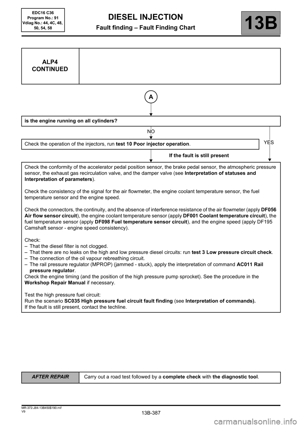
ALP4
CONTINUED
is the engine running on all cylinders?
Check the operation of the injectors, run test 10 Poor injector operation.
If the fault is still present
Check the conformity of the accelerator pedal position sensor, the brake pedal sensor, the atmospheric pressure
sensor, the exhaust gas recirculation valve, and the damper valve (see Interpretation of statuses and
Interpretation of parameters).
Check the consistency of the signal for the air flowmeter, the engine coolant temperature sensor, the fuel
temperature sensor and the engine speed.
Check the connectors, the continuity, and the absence of interference resistance of the air flowmeter (apply DF056
Air flow sensor circuit), the engine coolant temperature sensor (apply DF001 Coolant temperature circuit), the
fuel temperature sensor (apply DF098 Fuel temperature sensor circuit), and the engine speed (apply DF195
Camshaft sensor - engine speed consistency).
Check:
– That the diesel filter is not clogged.
– That there are no leaks on the high and low pressure diesel circuits: run test 3 Low pressure circuit check.
– The connection of the oil vapour rebreathing circuit.
– The rail pressure regulator (MPROP) (jammed - stuck), apply the interpretation of command AC011 Rail
pressure regulator.
Check the engine timing (and the position of the high pressure pump sprocket). See the procedure in the
Workshop Repair Manual if necessary.
Test the high pressure fuel circuit:
Run the scenario SC035 High pressure fuel circuit fault finding (see Interpretation of commands).
If the fault is still present, contact the techline.
A
NO
YES
EDC16 C36
Program No.: 91
Vdiag No.: 44, 4C, 48,
50, 54, 58
Page 393 of 431
13B-393
AFTER REPAIRCarry out a road test followed by a complete check with the diagnostic tool.
V9 MR-372-J84-13B450$190.mif
DIESEL INJECTION
Fault finding – Fault Finding Chart13B
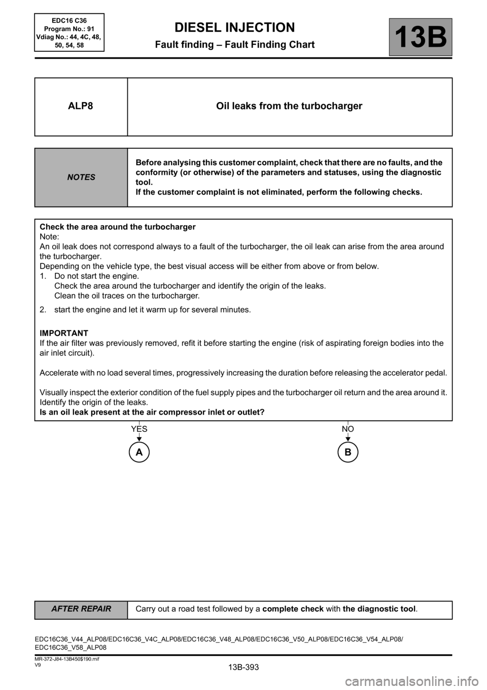
ALP8 Oil leaks from the turbocharger
NOTESBefore analysing this customer complaint, check that there are no faults, and the
conformity (or otherwise) of the parameters and statuses, using the diagnostic
tool.
If the customer complaint is not eliminated, perform the following checks.
Check the area around the turbocharger
Note:
An oil leak does not correspond always to a fault of the turbocharger, the oil leak can arise from the area around
the turbocharger.
Depending on the vehicle type, the best visual access will be either from above or from below.
1. Do not start the engine.
Check the area around the turbocharger and identify the origin of the leaks.
Clean the oil traces on the turbocharger.
2. start the engine and let it warm up for several minutes.
IMPORTANT
If the air filter was previously removed, refit it before starting the engine (risk of aspirating foreign bodies into the
air inlet circuit).
Accelerate with no load several times, progressively increasing the duration before releasing the accelerator pedal.
Visually inspect the exterior condition of the fuel supply pipes and the turbocharger oil return and the area around it.
Identify the origin of the leaks.
Is an oil leak present at the air compressor inlet or outlet?
YESNO
AB
EDC16C36_V44_ALP08/EDC16C36_V4C_ALP08/EDC16C36_V48_ALP08/EDC16C36_V50_ALP08/EDC16C36_V54_ALP08/
EDC16C36_V58_ALP08EDC16 C36
Program No.: 91
Vdiag No.: 44, 4C, 48,
50, 54, 58
Page 394 of 431
13B-394
AFTER REPAIRCarry out a road test followed by a complete check with the diagnostic tool.
V9 MR-372-J84-13B450$190.mif
DIESEL INJECTION
Fault finding – Fault Finding Chart13B
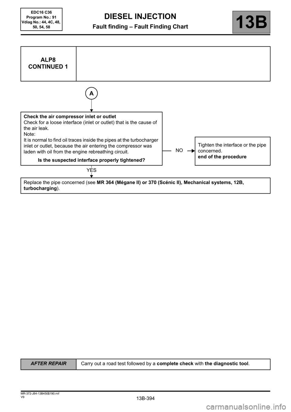
ALP8
CONTINUED 1
Check the air compressor inlet or outlet
Check for a loose interface (inlet or outlet) that is the cause of
the air leak.
Note:
It is normal to find oil traces inside the pipes at the turbocharger
inlet or outlet, because the air entering the compressor was
laden with oil from the engine rebreathing circuit.
Is the suspected interface properly tightened?Tighten the interface or the pipe
concerned.
end of the procedure
Replace the pipe concerned (see MR 364 (Mégane II) or 370 (Scénic II), Mechanical systems, 12B,
turbocharging).
A
NO
YES
EDC16 C36
Program No.: 91
Vdiag No.: 44, 4C, 48,
50, 54, 58
Page 395 of 431
13B-395
AFTER REPAIRCarry out a road test followed by a complete check with the diagnostic tool.
V9 MR-372-J84-13B450$190.mif
DIESEL INJECTION
Fault finding – Fault Finding Chart13B
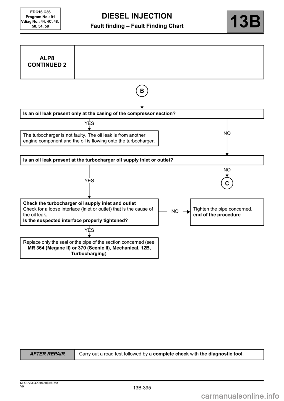
ALP8
CONTINUED 2
Is an oil leak present only at the casing of the compressor section?
The turbocharger is not faulty. The oil leak is from another
engine component and the oil is flowing onto the turbocharger.
Is an oil leak present at the turbocharger oil supply inlet or outlet?
Check the turbocharger oil supply inlet and outlet
Check for a loose interface (inlet or outlet) that is the cause of
the oil leak.
Is the suspected interface properly tightened?Tighten the pipe concerned.
end of the procedure
Replace only the seal or the pipe of the section concerned (see
MR 364 (Megane II) or 370 (Scenic II), Mechanical, 12B,
Turbocharging).
B
YES
NO
YES
NO
C
NO
YES
EDC16 C36
Program No.: 91
Vdiag No.: 44, 4C, 48,
50, 54, 58
Page 396 of 431
13B-396
AFTER REPAIRCarry out a road test followed by a complete check with the diagnostic tool.
V9 MR-372-J84-13B450$190.mif
DIESEL INJECTION
Fault finding – Fault Finding Chart13B
ALP8
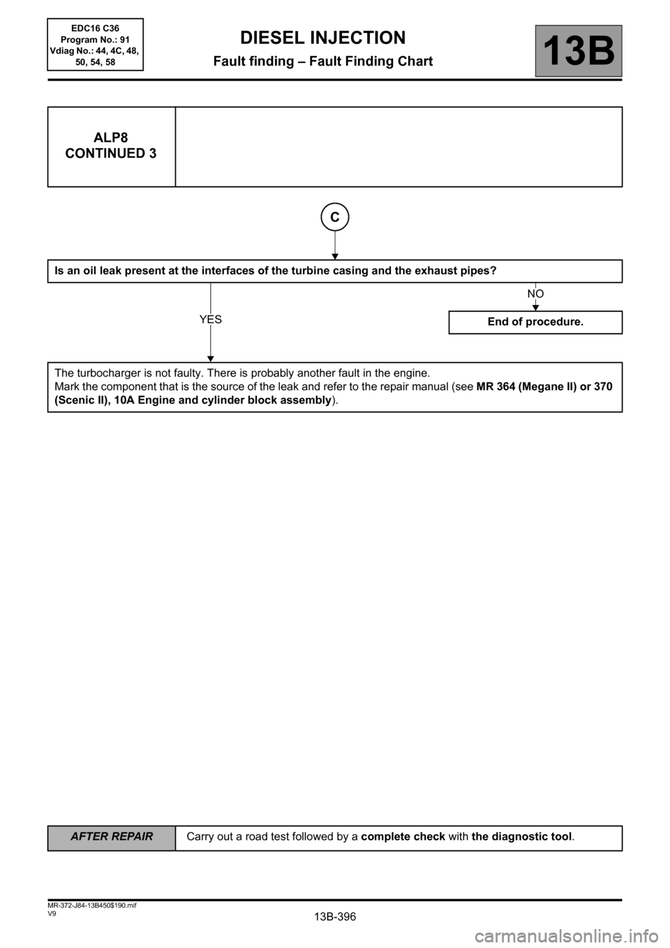
CONTINUED 3
Is an oil leak present at the interfaces of the turbine casing and the exhaust pipes?
End of procedure.
The turbocharger is not faulty. There is probably another fault in the engine.
Mark the component that is the source of the leak and refer to the repair manual (see MR 364 (Megane II) or 370
(Scenic II), 10A Engine and cylinder block assembly).
C
YES
NO
EDC16 C36
Program No.: 91
Vdiag No.: 44, 4C, 48,
50, 54, 58
Page 414 of 431
13B-414V9 MR-372-J84-13B450$200.mif
DIESEL INJECTION
Fault finding – Tests13B
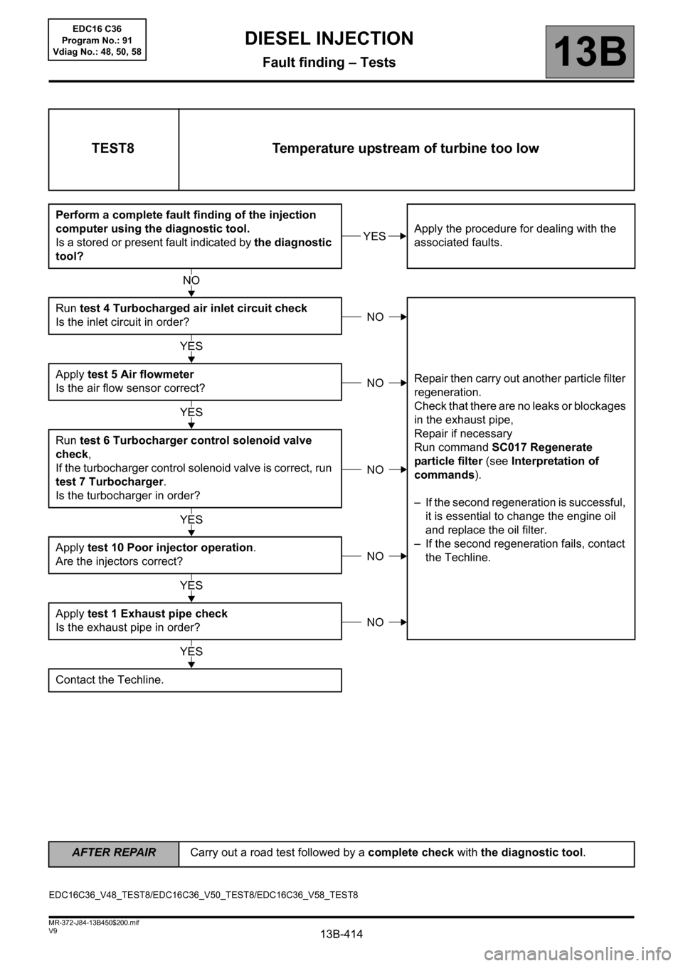
TEST8 Temperature upstream of turbine too low
Perform a complete fault finding of the injection
computer using the diagnostic tool.
Is a stored or present fault indicated by the diagnostic
tool?Apply the procedure for dealing with the
associated faults.
Run test 4 Turbocharged air inlet circuit check
Is the inlet circuit in order?
Repair then carry out another particle filter
regeneration.
Check that there are no leaks or blockages
in the exhaust pipe,
Repair if necessary
Run command SC017 Regenerate
particle filter (see Interpretation of
commands).
– If the second regeneration is successful,
it is essential to change the engine oil
and replace the oil filter.
– If the second regeneration fails, contact
the Techline. Apply test 5 Air flowmeter
Is the air flow sensor correct?
Run test 6 Turbocharger control solenoid valve
check,
If the turbocharger control solenoid valve is correct, run
test 7 Turbocharger.
Is the turbocharger in order?
Apply test 10 Poor injector operation.
Are the injectors correct?
Apply test 1 Exhaust pipe check
Is the exhaust pipe in order?
Contact the Techline.
YES
NO
NO
YES
NO
YES
NO
YES
NO
YES
NO
YES
EDC16C36_V48_TEST8/EDC16C36_V50_TEST8/EDC16C36_V58_TEST8
AFTER REPAIRCarry out a road test followed by a complete check with the diagnostic tool.
EDC16 C36
Program No.: 91
Vdiag No.: 48, 50, 58
Page 417 of 431
13B-417V9 MR-372-J84-13B450$200.mif
DIESEL INJECTION
Fault finding – Tests13B
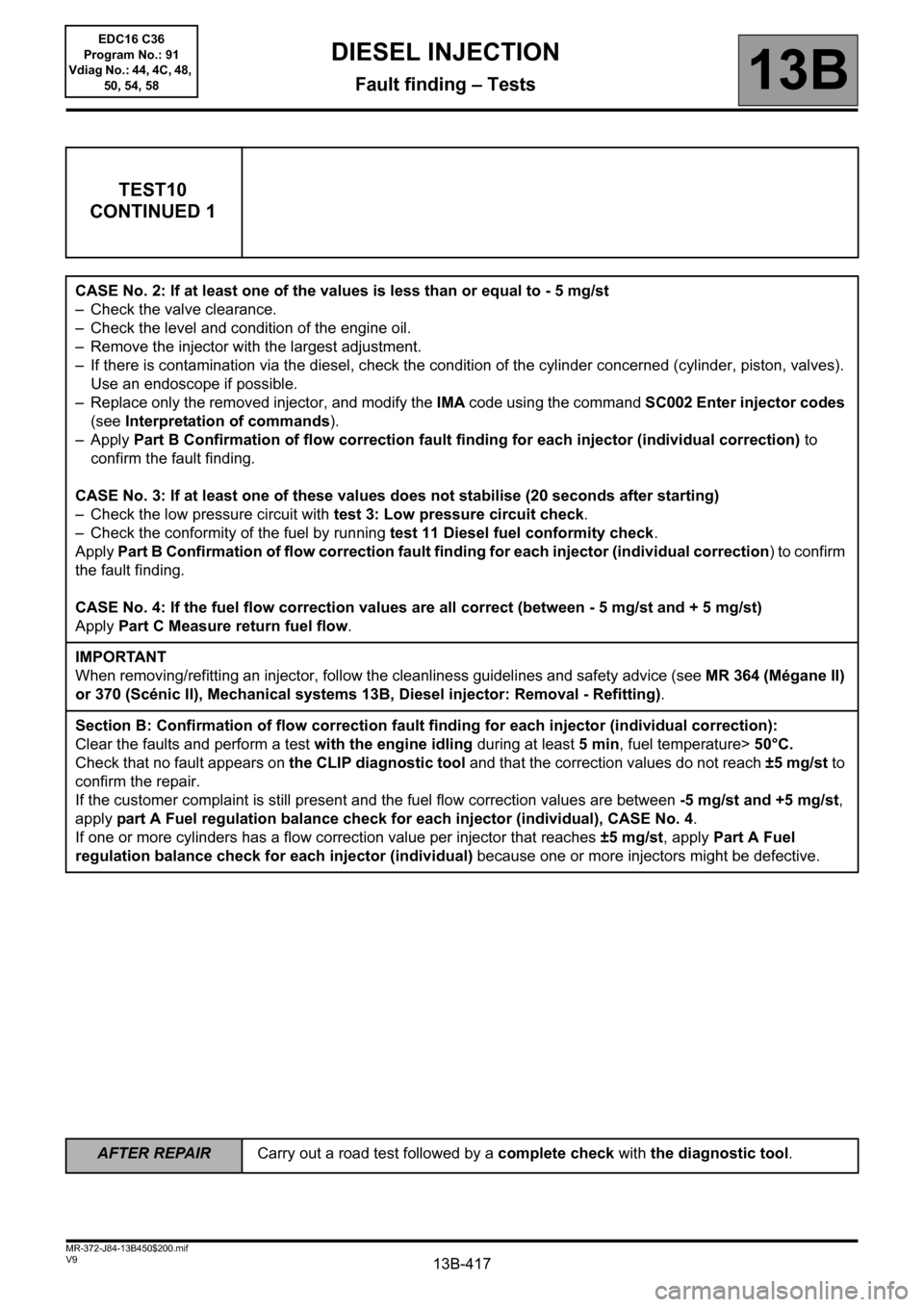
TEST10
CONTINUED 1
CASE No. 2: If at least one of the values is less than or equal to - 5 mg/st
– Check the valve clearance.
– Check the level and condition of the engine oil.
– Remove the injector with the largest adjustment.
– If there is contamination via the diesel, check the condition of the cylinder concerned (cylinder, piston, valves).
Use an endoscope if possible.
– Replace only the removed injector, and modify the IMA code using the command SC002 Enter injector codes
(see Interpretation of commands).
–Apply Part B Confirmation of flow correction fault finding for each injector (individual correction) to
confirm the fault finding.
CASE No. 3: If at least one of these values does not stabilise (20 seconds after starting)
– Check the low pressure circuit with test 3: Low pressure circuit check.
– Check the conformity of the fuel by running test 11 Diesel fuel conformity check.
Apply Part B Confirmation of flow correction fault finding for each injector (individual correction) to confirm
the fault finding.
CASE No. 4: If the fuel flow correction values are all correct (between - 5 mg/st and + 5 mg/st)
Apply Part C Measure return fuel flow.
IMPORTANT
When removing/refitting an injector, follow the cleanliness guidelines and safety advice (see MR 364 (Mégane II)
or 370 (Scénic II), Mechanical systems 13B, Diesel injector: Removal - Refitting).
Section B: Confirmation of flow correction fault finding for each injector (individual correction):
Clear the faults and perform a test with the engine idling during at least 5 min, fuel temperature> 50°C.
Check that no fault appears on the CLIP diagnostic tool and that the correction values do not reach ±5 mg/st to
confirm the repair.
If the customer complaint is still present and the fuel flow correction values are between -5 mg/st and +5 mg/st,
apply part A Fuel regulation balance check for each injector (individual), CASE No. 4.
If one or more cylinders has a flow correction value per injector that reaches ±5 mg/st, apply Part A Fuel
regulation balance check for each injector (individual) because one or more injectors might be defective.
AFTER REPAIRCarry out a road test followed by a complete check with the diagnostic tool.
EDC16 C36
Program No.: 91
Vdiag No.: 44, 4C, 48,
50, 54, 58