check engine RENAULT SCENIC 2011 J95 / 3.G Engine And Peripherals EDC16C36 Workshop Manual
[x] Cancel search | Manufacturer: RENAULT, Model Year: 2011, Model line: SCENIC, Model: RENAULT SCENIC 2011 J95 / 3.GPages: 431, PDF Size: 2.03 MB
Page 361 of 431
13B-361
AFTER REPAIRRepeat the conformity check in the interpretation of statuses and parameters
V9 MR-372-J84-13B450$170.mif
DIESEL INJECTION
Fault finding – Interpretation of commands13B
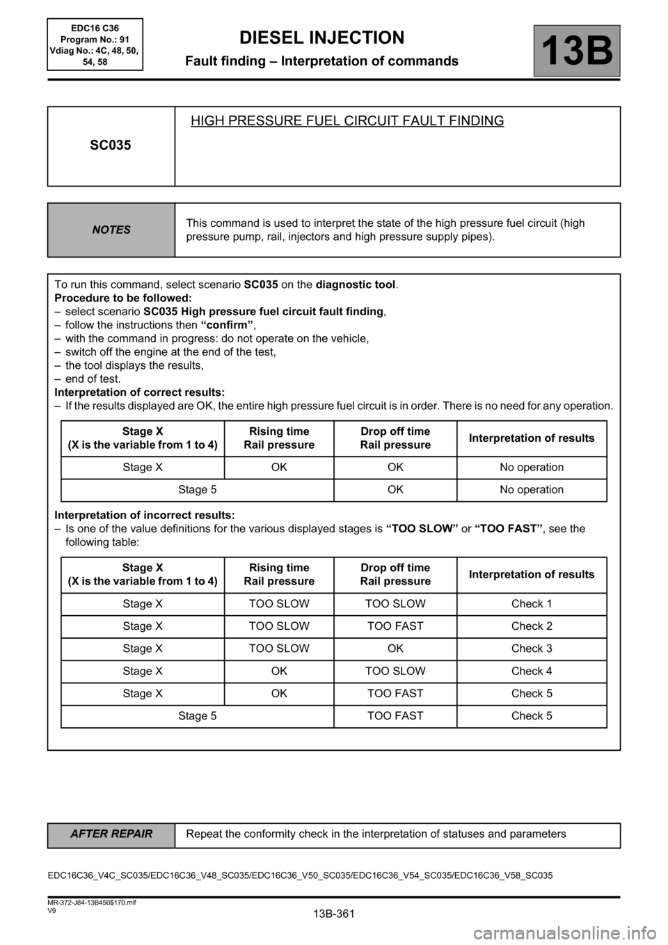
SC035HIGH PRESSURE FUEL CIRCUIT FAULT FINDING
NOTESThis command is used to interpret the state of the high pressure fuel circuit (high
pressure pump, rail, injectors and high pressure supply pipes).
To run this command, select scenario SC035 on the diagnostic tool.
Procedure to be followed:
– select scenario SC035 High pressure fuel circuit fault finding,
– follow the instructions then “confirm”,
– with the command in progress: do not operate on the vehicle,
– switch off the engine at the end of the test,
– the tool displays the results,
– end of test.
Interpretation of correct results:
– If the results displayed are OK, the entire high pressure fuel circuit is in order. There is no need for any operation.
Stage X
(X is the variable from 1 to 4)Rising time
Rail pressureDrop off time
Rail pressureInterpretation of results
Stage X OK OK No operation
Stage 5 OK No operation
Interpretation of incorrect results:
– Is one of the value definitions for the various displayed stages is “TOO SLOW” or “TOO FAST”, see the
following table:
Stage X
(X is the variable from 1 to 4)Rising time
Rail pressureDrop off time
Rail pressureInterpretation of results
Stage X TOO SLOW TOO SLOW Check 1
Stage X TOO SLOW TOO FAST Check 2
Stage X TOO SLOW OK Check 3
Stage X OK TOO SLOW Check 4
Stage X OK TOO FAST Check 5
Stage 5 TOO FAST Check 5
EDC16C36_V4C_SC035/EDC16C36_V48_SC035/EDC16C36_V50_SC035/EDC16C36_V54_SC035/EDC16C36_V58_SC035 EDC16 C36
Program No.: 91
Vdiag No.: 4C, 48, 50,
54, 58
Page 363 of 431
13B-363
AFTER REPAIRRepeat the conformity check in the interpretation of statuses and parameters
V9 MR-372-J84-13B450$170.mif
DIESEL INJECTION
Fault finding – Interpretation of commands13B
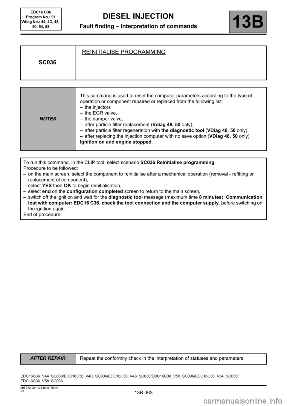
SC036REINITIALISE PROGRAMMING
NOTESThis command is used to reset the computer parameters according to the type of
operation or component repaired or replaced from the following list:
– the injectors
– the EGR valve,
– the damper valve,
– after particle filter replacement (Vdiag 48, 50 only),
– after particle filter regeneration with the diagnostic tool (VDiag 48, 50 only),
– after replacing the injection computer with no save option (VDiag 48, 50 only).
Ignition on and engine stopped.
To run this command, in the CLIP tool, select scenario SC036 Reinitialise programming.
Procedure to be followed:
– on the main screen, select the component to reinitialise after a mechanical operation (removal - refitting or
replacement of component),
–select YES then OK to begin reinitialisation,
–select end on the configuration completed screen to return to the main screen,
– switch off the ignition and wait for the diagnostic tool message (maximum time 8 minutes): Communication
lost with computer: EDC16 C36, check the tool connection and the computer supply. before switching on
the ignition again.
End of procedure.
EDC16C36_V44_SC036/EDC16C36_V4C_SC036/EDC16C36_V48_SC036/EDC16C36_V50_SC036/EDC16C36_V54_SC036/
EDC16C36_V58_SC036EDC16 C36
Program No.: 91
Vdiag No.: 44, 4C, 48,
50, 54, 58
Page 365 of 431
13B-365
AFTER REPAIRRepeat the conformity check in the interpretation of statuses and parameters
V9 MR-372-J84-13B450$170.mif
DIESEL INJECTION
Fault finding – Interpretation of commands13B
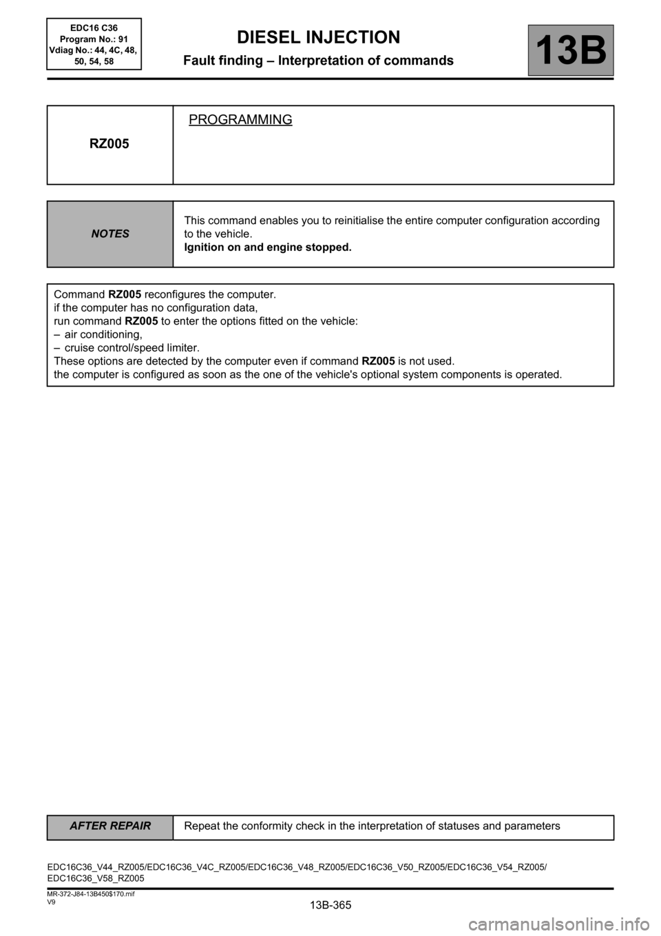
RZ005PROGRAMMING
NOTESThis command enables you to reinitialise the entire computer configuration according
to the vehicle.
Ignition on and engine stopped.
Command RZ005 reconfigures the computer.
if the computer has no configuration data,
run command RZ005 to enter the options fitted on the vehicle:
– air conditioning,
– cruise control/speed limiter.
These options are detected by the computer even if command RZ005 is not used.
the computer is configured as soon as the one of the vehicle's optional system components is operated.
EDC16C36_V44_RZ005/EDC16C36_V4C_RZ005/EDC16C36_V48_RZ005/EDC16C36_V50_RZ005/EDC16C36_V54_RZ005/
EDC16C36_V58_RZ005EDC16 C36
Program No.: 91
Vdiag No.: 44, 4C, 48,
50, 54, 58
Page 366 of 431
13B-366
AFTER REPAIRRepeat the conformity check in the interpretation of statuses and parameters
V9 MR-372-J84-13B450$170.mif
DIESEL INJECTION
Fault finding – Interpretation of commands13B
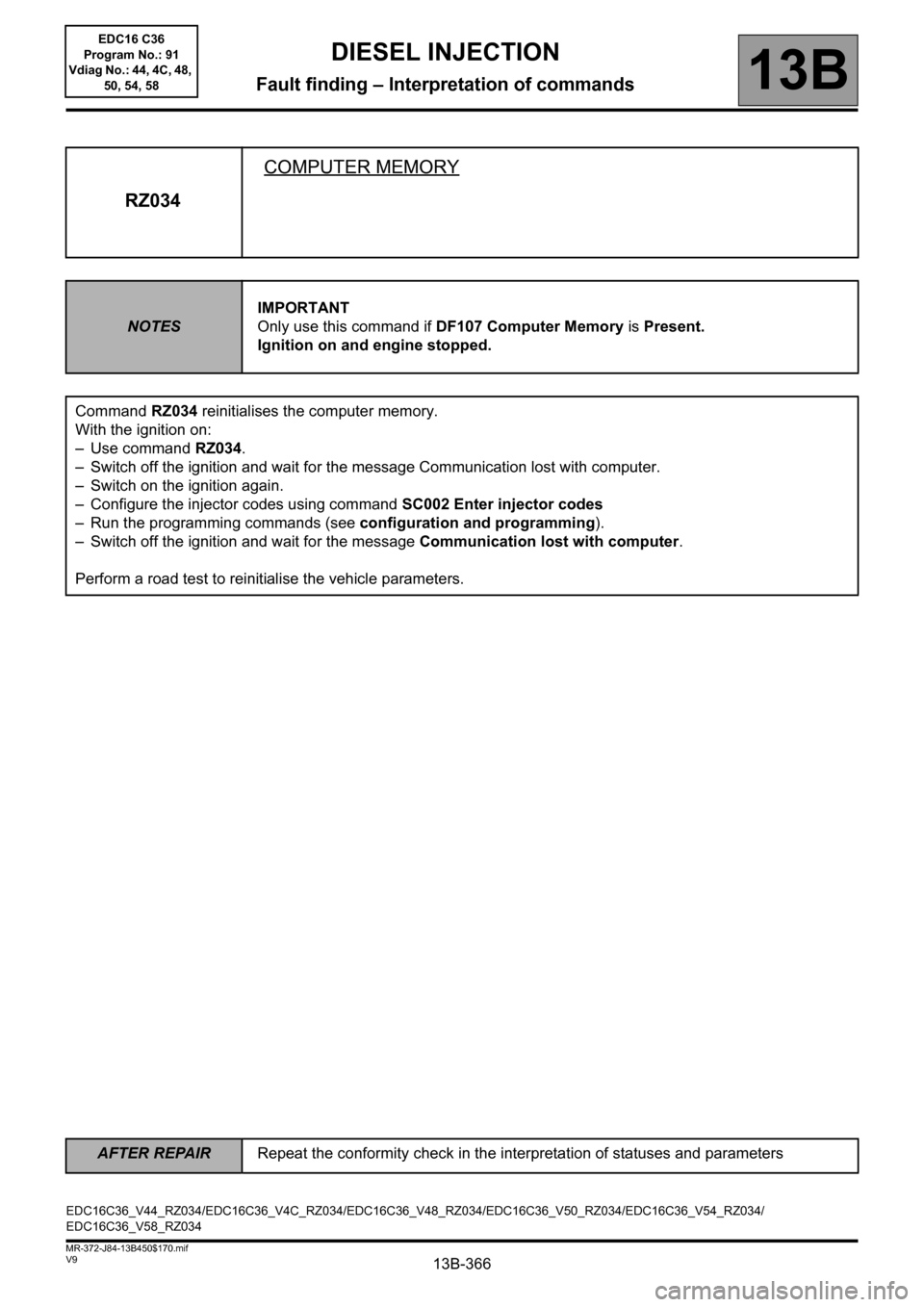
RZ034COMPUTER MEMORY
NOTESIMPORTANT
Only use this command if DF107 Computer Memory is Present.
Ignition on and engine stopped.
Command RZ034 reinitialises the computer memory.
With the ignition on:
– Use command RZ034.
– Switch off the ignition and wait for the message Communication lost with computer.
– Switch on the ignition again.
– Configure the injector codes using command SC002 Enter injector codes
– Run the programming commands (see configuration and programming).
– Switch off the ignition and wait for the message Communication lost with computer.
Perform a road test to reinitialise the vehicle parameters.
EDC16C36_V44_RZ034/EDC16C36_V4C_RZ034/EDC16C36_V48_RZ034/EDC16C36_V50_RZ034/EDC16C36_V54_RZ034/
EDC16C36_V58_RZ034EDC16 C36
Program No.: 91
Vdiag No.: 44, 4C, 48,
50, 54, 58
Page 367 of 431
13B-367
AFTER REPAIRRepeat the conformity check in the interpretation of statuses and parameters
V9 MR-372-J84-13B450$170.mif
DIESEL INJECTION
Fault finding – Interpretation of commands13B
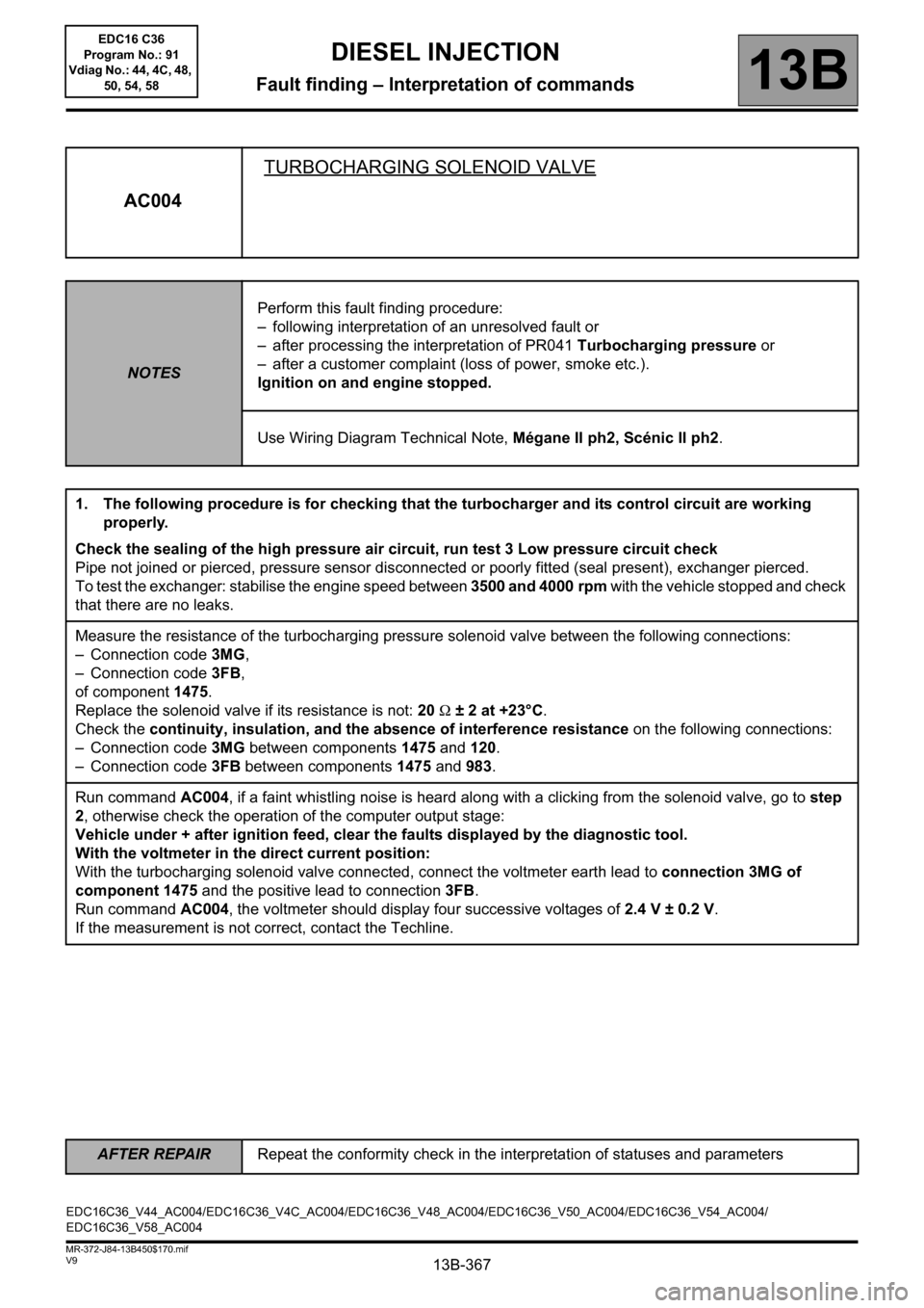
AC004TURBOCHARGING SOLENOID VALVE
NOTESPerform this fault finding procedure:
– following interpretation of an unresolved fault or
– after processing the interpretation of PR041 Turbocharging pressure or
– after a customer complaint (loss of power, smoke etc.).
Ignition on and engine stopped.
Use Wiring Diagram Technical Note, Mégane II ph2, Scénic II ph2.
1. The following procedure is for checking that the turbocharger and its control circuit are working
properly.
Check the sealing of the high pressure air circuit, run test 3 Low pressure circuit check
Pipe not joined or pierced, pressure sensor disconnected or poorly fitted (seal present), exchanger pierced.
To test the exchanger: stabilise the engine speed between 3500 and 4000 rpm with the vehicle stopped and check
that there are no leaks.
Measure the resistance of the turbocharging pressure solenoid valve between the following connections:
– Connection code 3MG,
– Connection code 3FB,
of component 1475.
Replace the solenoid valve if its resistance is not: 20 Ω ± 2 at +23°C.
Check the continuity, insulation, and the absence of interference resistance on the following connections:
– Connection code 3MG between components 1475 and 120.
– Connection code 3FB between components 1475 and 983.
Run command AC004, if a faint whistling noise is heard along with a clicking from the solenoid valve, go to step
2, otherwise check the operation of the computer output stage:
Vehicle under + after ignition feed, clear the faults displayed by the diagnostic tool.
With the voltmeter in the direct current position:
With the turbocharging solenoid valve connected, connect the voltmeter earth lead to connection 3MG of
component 1475 and the positive lead to connection3FB.
Run command AC004, the voltmeter should display four successive voltages of 2.4 V ± 0.2 V.
If the measurement is not correct, contact the Techline.
EDC16C36_V44_AC004/EDC16C36_V4C_AC004/EDC16C36_V48_AC004/EDC16C36_V50_AC004/EDC16C36_V54_AC004/
EDC16C36_V58_AC004EDC16 C36
Program No.: 91
Vdiag No.: 44, 4C, 48,
50, 54, 58
Page 368 of 431

13B-368
AFTER REPAIRRepeat the conformity check in the interpretation of statuses and parameters
V9 MR-372-J84-13B450$170.mif
DIESEL INJECTION
Fault finding – Interpretation of commands13B
AC004
CONTINUED
2. Turbocharger control circuit check:
– With the engine stopped, make sure that the control rod is in the resting position.
– Start the engine and make sure that the control rod actuates to the upper stop.
(when the engine is switched off, the control rod should return to the rest position)
If the control rod does not move correctly, carry out the following checks:
1) Control vacuum check:
– Disconnect the solenoid valve inlet hose and connect it to a pressure gauge.
– Start the engine and run it at a stable idle speed.
– If the vacuum does not reach 400 mbar ± 150: check the vacuum pressure circuit from the vacuum pump.
– Stop the engine, reconnect the intake hose and go to step no. 2.
2) Solenoid valve control check:
– Disconnect the solenoid valve outlet hose.
– Start the engine and run it at a stable idle speed.
– Place your hand on the solenoid valve and block the outlet union with your thumb.
– If there is no perceptible vibration of the solenoid valve, contact the Techline.
3) Solenoid valve operation check:
– Connect the pressure gauge to the solenoid valve outlet union.
– Start the engine and run it at a stable idle speed.
If the vacuum does not reach 400 mbar ± 150, replace the solenoid valve.
EDC16 C36
Program No.: 91
Vdiag No.: 44, 4C, 48,
50, 54, 58
Page 369 of 431
13B-369
AFTER REPAIRRepeat the conformity check in the interpretation of statuses and parameters
V9 MR-372-J84-13B450$170.mif
DIESEL INJECTION
Fault finding – Interpretation of commands13B
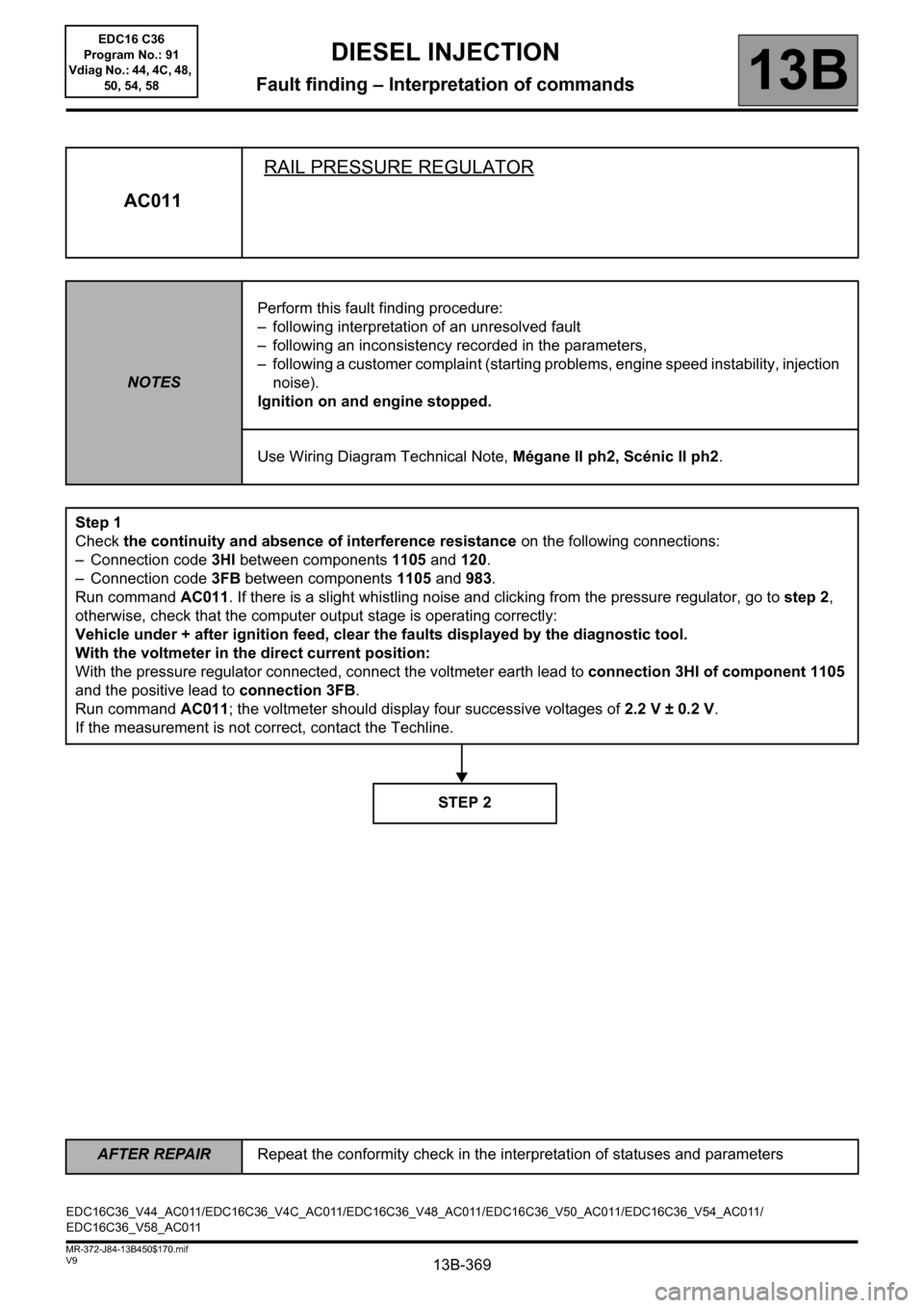
AC011RAIL PRESSURE REGULATOR
NOTESPerform this fault finding procedure:
– following interpretation of an unresolved fault
– following an inconsistency recorded in the parameters,
– following a customer complaint (starting problems, engine speed instability, injection
noise).
Ignition on and engine stopped.
Use Wiring Diagram Technical Note, Mégane II ph2, Scénic II ph2.
Step 1
Check the continuity and absence of interference resistance on the following connections:
– Connection code 3HI between components 1105 and 120.
– Connection code 3FB between components 1105 and 983.
Run command AC011. If there is a slight whistling noise and clicking from the pressure regulator, go to step 2,
otherwise, check that the computer output stage is operating correctly:
Vehicle under + after ignition feed, clear the faults displayed by the diagnostic tool.
With the voltmeter in the direct current position:
With the pressure regulator connected, connect the voltmeter earth lead to connection 3HI of component 1105
and the positive lead to connection 3FB.
Run command AC011; the voltmeter should display four successive voltages of 2.2 V ± 0.2 V.
If the measurement is not correct, contact the Techline.
STEP 2
EDC16C36_V44_AC011/EDC16C36_V4C_AC011/EDC16C36_V48_AC011/EDC16C36_V50_AC011/EDC16C36_V54_AC011/
EDC16C36_V58_AC011EDC16 C36
Program No.: 91
Vdiag No.: 44, 4C, 48,
50, 54, 58
Page 370 of 431

13B-370
AFTER REPAIRRepeat the conformity check in the interpretation of statuses and parameters
V9 MR-372-J84-13B450$170.mif
DIESEL INJECTION
Fault finding – Interpretation of commands13B
AC011
CONTINUED
Step 2
In the event of rail overpressure:
Check that there are no air bubbles in the diesel fuel low pressure circuit.
Check that the rail pressure sensor is operating correctly.
Consult the interpretation of parameter PR038 Rail pressure.
If these checks reveal no irregularities, replace the regulator.
in the event of rail underpressure:
Check that the rail pressure sensor is operating correctly.
Consult the interpretation of parameter PR038 Rail pressure.
Check the low pressure diesel circuit priming.
Check the conformity of the diesel filter connections.
Check the condition of the filter (clogging and water saturation).
Check that there are no air bubbles between the filter and the high pressure pump.
Check the sealing of the low and high pressure diesel fuel systems: use ALP6 Fuel circuit leaks (visual
inspections, touch tests, odours, etc.) on:
pump body, pressure release valve, pipes, rail and injectors unions, injector wells, etc.
Check the conformity of the seal fitting on the pressure regulator.
Check the operation of the injectors, run Test 10 Poor injector operation.
Carry out the necessary repairs.
If the engine starts:
Clear any faults.
Check the pressure regulator by applying (see ALP7 Rough idle).
With the engine warm, leave it to idle for a few minutes (3 to 5 minutes):
– If it stalls and the fault reappears, replace the regulator.
– If it does not stall, stabilise the engine speed at 2000 rpm(1 minute) then accelerate at full load until it cuts out.
If the engine stalls, contact the Techline
If the engine does not startor there is no timing:
first, replace the regulator and if the fault is still present, contact the Techline.
EDC16 C36
Program No.: 91
Vdiag No.: 44, 4C, 48,
50, 54, 58
Page 371 of 431

13B-371
AFTER REPAIRRepeat the conformity check in the interpretation of statuses and parameters
V9 MR-372-J84-13B450$170.mif
DIESEL INJECTION
Fault finding – Interpretation of commands13B
AC012DAMPER VALVE
NOTESCarry out this interpretation:
– after DF226 Damper valve
– or after a customer complaint (starting faults, poor performance).
Ignition on and engine stopped.
Use Wiring Diagram Technical Note, Mégane II ph2, Scénic II ph2.
Check the continuity, insulation and absence of interference resistance on the following connections:
– Connection code 3VN,
– Connection code 3VM,
between components 1461 and 120.
Check for +12 V on connection 3FB of component 1461.
Check for earth on connectionNT of component1461.
If there is a repair method (see Technical Note 6015A, Repairing electrical wiring, Wiring: Precautions for
repair), repair the wiring, otherwise replace it.
With the vehicle ignition on, and the engine stopped:
Check that the damper valve is open.
If not, clean or replace the damper valve.
Actuate the valve using command AC012 and check the damper valve travel and the rest position of the valve.
Check the operation of the computer output stage with a voltmeter:
Actuate the valve with command AC012.
Positive lead to connection3FB and negative lead to connection3VN of component1461.
The voltmeter should display three cycles of ON-OFF (12.5 V then return to 0V).
If the measurement is correct, replace the damper valve.
If the measurement does not show any operation, contact the Techline.
EDC16C36_V44_AC012/EDC16C36_V4C_AC012/EDC16C36_V48_AC012/EDC16C36_V50_AC012/EDC16C36_V54_AC012/
EDC16C36_V58_AC012EDC16 C36
Program No.: 91
Vdiag No.: 44, 4C, 48,
50, 54, 58
Page 372 of 431

13B-372
AFTER REPAIRRepeat the conformity check in the interpretation of statuses and parameters
V9 MR-372-J84-13B450$170.mif
DIESEL INJECTION
Fault finding – Interpretation of commands13B
AC037PREHEATING RELAY
NOTESThis command is only run if fault DF025 Preheating unit diagnostic connection or
DF017 Preheating unit control circuit is present or stored and if no other fault is
present.
Ignition on and engine stopped.
Use Wiring Diagram Technical Note, Mégane II ph2, Scénic II ph2.
Before applying the following fault finding procedure, check that the battery voltage is not below 12 V.
Otherwise, recharge the battery.
Check the connections on the preheating unit, heater plugs and injection computer.
If there is a repair method (see Technical Note 6015A, Repairing electrical wiring, Wiring: Precautions for
repair), repair the wiring, otherwise replace it.
Measure the resistance of the heater plugs. If this resistance is > 2 Ω, replace the defective plug(s).
Check the continuity and the absence of interference resistance on the following connections:
– Connection code 37AA between components257 and 681.
– Connection code 37AB between components 257 and 682.
– Connection code 37AC between components 257 and 683.
– Connection code 37AZ between components 257 and 680.
Check the condition of fuse FM12 (70 A) of the preheating unit supply. Replace it if necessary.
Then check for +12 V on connection BP35 of component 257.
Check the continuity, insulation, and the absence of interference resistance of the following connections:
– Connection code 3FF,
– Connection code 3FY,
Between components 257 and 120.
If the fault is still present, replace the pre-postheating unit.
EDC16C36_V44_AC037/EDC16C36_V4C_AC037/EDC16C36_V48_AC037/EDC16C36_V50_AC037/EDC16C36_V54_AC037/
EDC16C36_V58_AC037EDC16 C36
Program No.: 91
Vdiag No.: 44, 4C, 48,
50, 54, 58