check engine RENAULT SCENIC 2011 J95 / 3.G Engine And Peripherals EDC16C36 Workshop Manual
[x] Cancel search | Manufacturer: RENAULT, Model Year: 2011, Model line: SCENIC, Model: RENAULT SCENIC 2011 J95 / 3.GPages: 431, PDF Size: 2.03 MB
Page 398 of 431
13B-398
AFTER REPAIRCarry out a road test followed by a complete check with the diagnostic tool.
V9 MR-372-J84-13B450$190.mif
DIESEL INJECTION
Fault finding – Fault Finding Chart13B
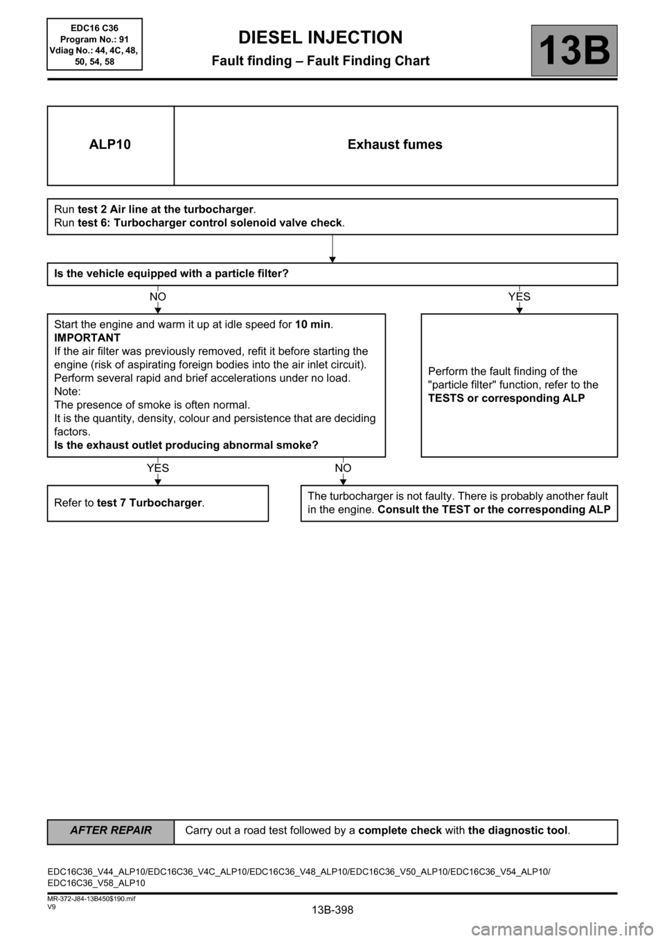
ALP10 Exhaust fumes
Run test 2 Air line at the turbocharger.
Run test 6: Turbocharger control solenoid valve check.
Is the vehicle equipped with a particle filter?
Start the engine and warm it up at idle speed for 10 min.
IMPORTANT
If the air filter was previously removed, refit it before starting the
engine (risk of aspirating foreign bodies into the air inlet circuit).
Perform several rapid and brief accelerations under no load.
Note:
The presence of smoke is often normal.
It is the quantity, density, colour and persistence that are deciding
factors.
Is the exhaust outlet producing abnormal smoke?Perform the fault finding of the
"particle filter" function, refer to the
TESTS or corresponding ALP
Refer to test 7 Turbocharger.The turbocharger is not faulty. There is probably another fault
in the engine. Consult the TEST or the corresponding ALP
NOYES
YESNO
EDC16C36_V44_ALP10/EDC16C36_V4C_ALP10/EDC16C36_V48_ALP10/EDC16C36_V50_ALP10/EDC16C36_V54_ALP10/
EDC16C36_V58_ALP10EDC16 C36
Program No.: 91
Vdiag No.: 44, 4C, 48,
50, 54, 58
Page 399 of 431
13B-399
AFTER REPAIRCarry out a road test followed by a complete check with the diagnostic tool.
V9 MR-372-J84-13B450$190.mif
DIESEL INJECTION
Fault finding – Fault Finding Chart13B
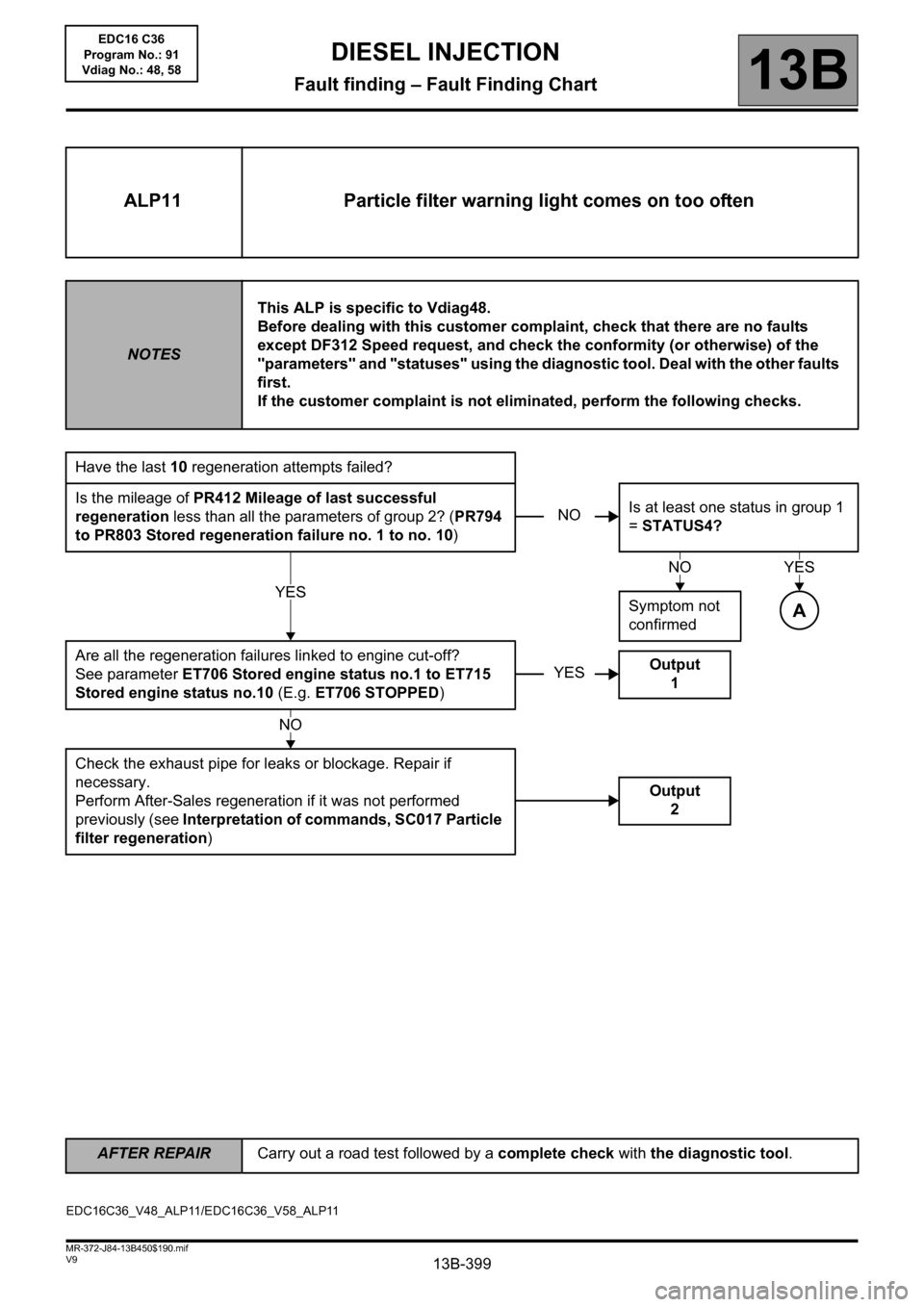
ALP11 Particle filter warning light comes on too often
NOTESThis ALP is specific to Vdiag48.
Before dealing with this customer complaint, check that there are no faults
except DF312 Speed request, and check the conformity (or otherwise) of the
"parameters" and "statuses" using the diagnostic tool. Deal with the other faults
first.
If the customer complaint is not eliminated, perform the following checks.
Have the last 10 regeneration attempts failed?
Is the mileage of PR412 Mileage of last successful
regeneration less than all the parameters of group 2? (PR794
to PR803 Stored regeneration failure no. 1 to no. 10)Is at least one status in group 1
= STATUS4?
Symptom not
confirmed
Are all the regeneration failures linked to engine cut-off?
See parameter ET706 Stored engine status no.1 to ET715
Stored engine status no.10 (E.g. ET706 STOPPED)
Check the exhaust pipe for leaks or blockage. Repair if
necessary.
Perform After-Sales regeneration if it was not performed
previously (see Interpretation of commands, SC017 Particle
filter regeneration)
NO
YES
NOYES
A
YESOutput
1
NO
Output
2
EDC16C36_V48_ALP11/EDC16C36_V58_ALP11EDC16 C36
Program No.: 91
Vdiag No.: 48, 58
Page 403 of 431
13B-403
AFTER REPAIRCarry out a road test followed by a complete check with the diagnostic tool.
V9 MR-372-J84-13B450$190.mif
DIESEL INJECTION
Fault finding – Fault Finding Chart13B
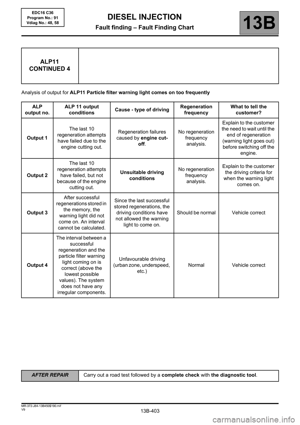
Analysis of output for ALP11 Particle filter warning light comes on too frequently
ALP11
CONTINUED 4
ALP
output no.ALP 11 output
conditionsCause - type of drivingRegeneration
frequencyWhat to tell the
customer?
Output 1The last 10
regeneration attempts
have failed due to the
engine cutting out.Regeneration failures
caused by engine cut-
off.No regeneration
frequency
analysis.Explain to the customer
the need to wait until the
end of regeneration
(warning light goes out)
before switching off the
engine.
Output 2The last 10
regeneration attempts
have failed, but not
because of the engine
cutting out.Unsuitable driving
conditionsNo regeneration
frequency
analysis.Explain to the customer
the driving criteria for
when the warning light
comes on.
Output 3After successful
regenerations stored in
the memory, the
warning light did not
come on. An interval
cannot be calculated.Since the last successful
stored regenerations, the
driving conditions have
not allowed the warning
light to come on.Should be normal Vehicle correct
Output 4The interval between a
successful
regeneration and the
particle filter warning
light coming on is
correct (above the
lowest possible
values). The system
does not have any
irregular components.Unfavourable driving
(urban zone, underspeed,
etc.)Normal Vehicle correct
EDC16 C36
Program No.: 91
Vdiag No.: 48, 58
Page 404 of 431
13B-404V9 MR-372-J84-13B450$200.mif
13B
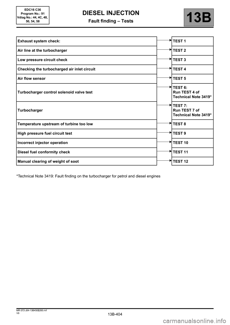
*Technical Note 3419: Fault finding on the turbocharger for petrol and diesel enginesExhaust system check: TEST 1
Air line at the turbocharger TEST 2
Low pressure circuit check TEST 3
Checking the turbocharged air inlet circuit TEST 4
Air flow sensorTEST 5
Turbocharger control solenoid valve testTEST 6:
Run TEST 4 of
Technical Note 3419*
TurbochargerTEST 7:
Run TEST 7 of
Technical Note 3419*
Temperature upstream of turbine too low TEST 8
High pressure fuel circuit test TEST 9
Incorrect injector operation TEST 10
Diesel fuel conformity check TEST 11
Manual clearing of weight of soot TEST 12
DIESEL INJECTION
Fault finding – Tests
EDC16 C36
Program No.: 91
Vdiag No.: 44, 4C, 48,
50, 54, 58
Page 405 of 431
13B-405V9 MR-372-J84-13B450$200.mif
DIESEL INJECTION
Fault finding – Tests13B
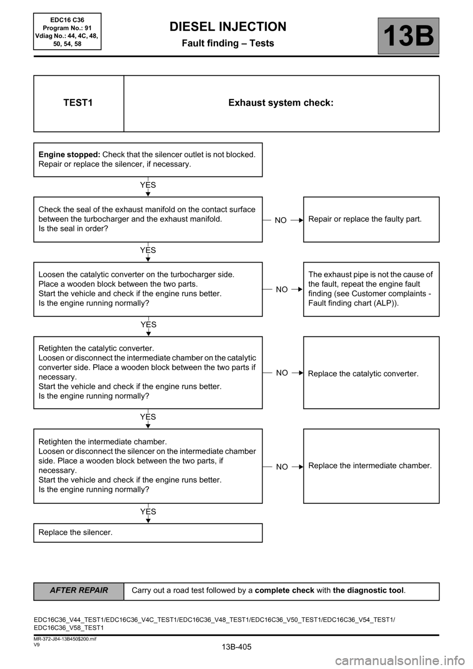
TEST1 Exhaust system check:
Engine stopped: Check that the silencer outlet is not blocked.
Repair or replace the silencer, if necessary.
Check the seal of the exhaust manifold on the contact surface
between the turbocharger and the exhaust manifold.
Is the seal in order?Repair or replace the faulty part.
Loosen the catalytic converter on the turbocharger side.
Place a wooden block between the two parts.
Start the vehicle and check if the engine runs better.
Is the engine running normally?The exhaust pipe is not the cause of
the fault, repeat the engine fault
finding (see Customer complaints -
Fault finding chart (ALP)).
Retighten the catalytic converter.
Loosen or disconnect the intermediate chamber on the catalytic
converter side. Place a wooden block between the two parts if
necessary.
Start the vehicle and check if the engine runs better.
Is the engine running normally?Replace the catalytic converter.
Retighten the intermediate chamber.
Loosen or disconnect the silencer on the intermediate chamber
side. Place a wooden block between the two parts, if
necessary.
Start the vehicle and check if the engine runs better.
Is the engine running normally?Replace the intermediate chamber.
Replace the silencer.
YES
NO
YES
NO
YES
NO
YES
NO
YES
EDC16C36_V44_TEST1/EDC16C36_V4C_TEST1/EDC16C36_V48_TEST1/EDC16C36_V50_TEST1/EDC16C36_V54_TEST1/
EDC16C36_V58_TEST1
AFTER REPAIRCarry out a road test followed by a complete check with the diagnostic tool.
EDC16 C36
Program No.: 91
Vdiag No.: 44, 4C, 48,
50, 54, 58
Page 407 of 431
13B-407V9 MR-372-J84-13B450$200.mif
DIESEL INJECTION
Fault finding – Tests13B
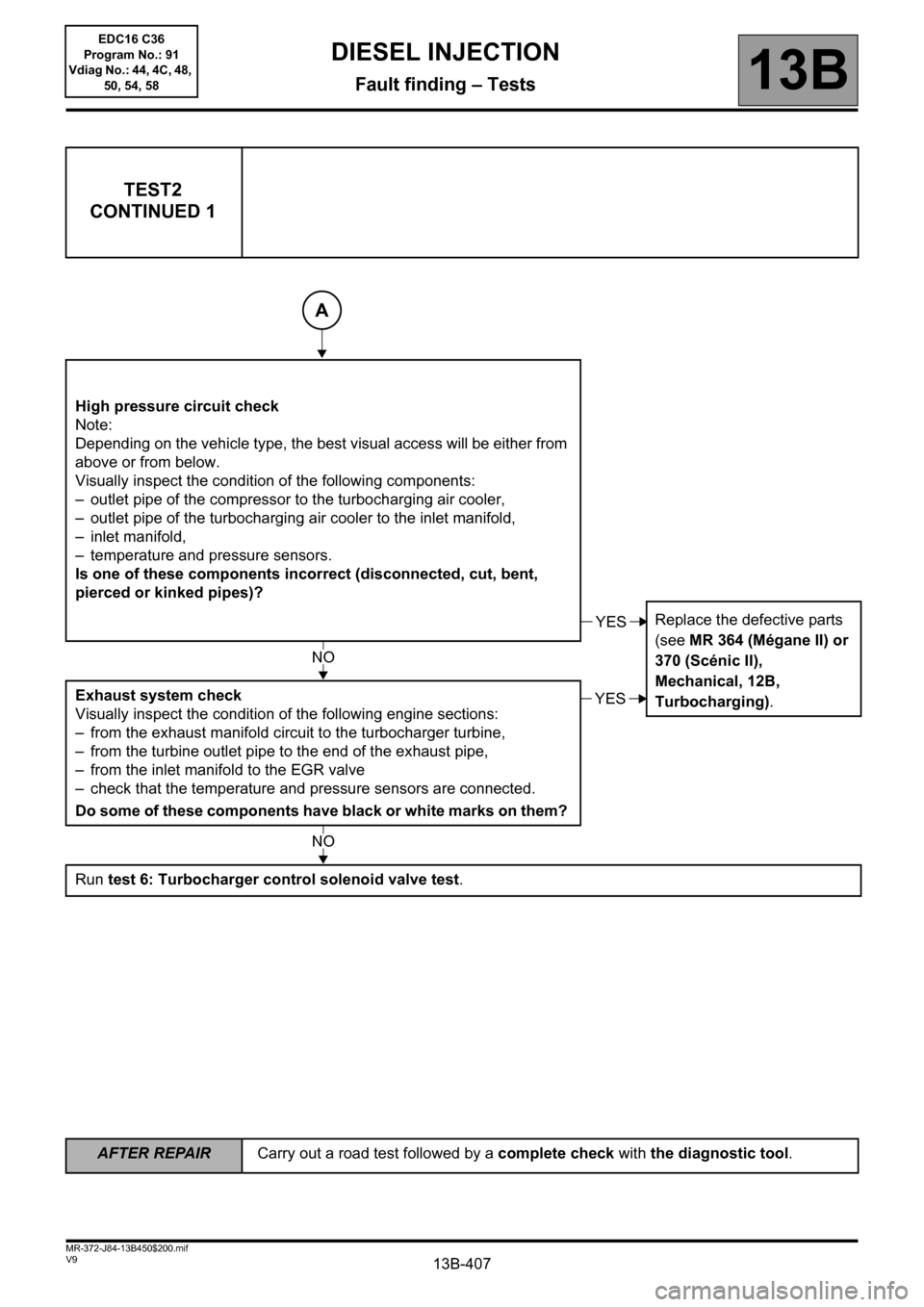
TEST2
CONTINUED 1
High pressure circuit check
Note:
Depending on the vehicle type, the best visual access will be either from
above or from below.
Visually inspect the condition of the following components:
– outlet pipe of the compressor to the turbocharging air cooler,
– outlet pipe of the turbocharging air cooler to the inlet manifold,
– inlet manifold,
– temperature and pressure sensors.
Is one of these components incorrect (disconnected, cut, bent,
pierced or kinked pipes)?
Replace the defective parts
(see MR 364 (Mégane II) or
370 (Scénic II),
Mechanical, 12B,
Turbocharging). Exhaust system check
Visually inspect the condition of the following engine sections:
– from the exhaust manifold circuit to the turbocharger turbine,
– from the turbine outlet pipe to the end of the exhaust pipe,
– from the inlet manifold to the EGR valve
– check that the temperature and pressure sensors are connected.
Do some of these components have black or white marks on them?
Run test 6: Turbocharger control solenoid valve test.
A
YES
NO
YES
NO
AFTER REPAIRCarry out a road test followed by a complete check with the diagnostic tool.
EDC16 C36
Program No.: 91
Vdiag No.: 44, 4C, 48,
50, 54, 58
Page 408 of 431
13B-408V9 MR-372-J84-13B450$200.mif
DIESEL INJECTION
Fault finding – Tests13B
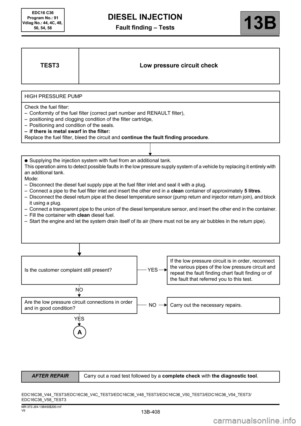
TEST3 Low pressure circuit check
HIGH PRESSURE PUMP
Check the fuel filter:
– Conformity of the fuel filter (correct part number and RENAULT filter),
– positioning and clogging condition of the filter cartridge,
– Positioning and condition of the seals.
– if there is metal swarf in the filter:
Replace the fuel filter, bleed the circuit and continue the fault finding procedure.
●Supplying the injection system with fuel from an additional tank.
This operation aims to detect possible faults in the low pressure supply system of a vehicle by replacing it entirely with
an additional tank.
Mode:
– Disconnect the diesel fuel supply pipe at the fuel filter inlet and seal it with a plug.
– Connect a pipe to the fuel filter inlet and insert the other end in a clean container of approximately 5litres.
– Disconnect the diesel return pipe at the diesel temperature sensor (pump return and injector return join), and block
it using a plug.
– Connect a transparent pipe to the union of the diesel temperature sensor, and insert the other end in the container.
– Fill the container with clean diesel fuel.
– Start the engine and let the system drain itself of its air (there must not be any air bubbles in the return pipe).
Is the customer complaint still present?If the low pressure circuit is in order, reconnect
the various pipes of the low pressure circuit and
repeat the fault finding chart fault finding or of
the fault that referred you to this test.
Are the low pressure circuit connections in order
and in good condition?Carry out the necessary repairs.
YES
NO
NO
YES
A
EDC16C36_V44_TEST3/EDC16C36_V4C_TEST3/EDC16C36_V48_TEST3/EDC16C36_V50_TEST3/EDC16C36_V54_TEST3/
EDC16C36_V58_TEST3
AFTER REPAIRCarry out a road test followed by a complete check with the diagnostic tool.
EDC16 C36
Program No.: 91
Vdiag No.: 44, 4C, 48,
50, 54, 58
Page 410 of 431
13B-410V9 MR-372-J84-13B450$200.mif
DIESEL INJECTION
Fault finding – Tests13B
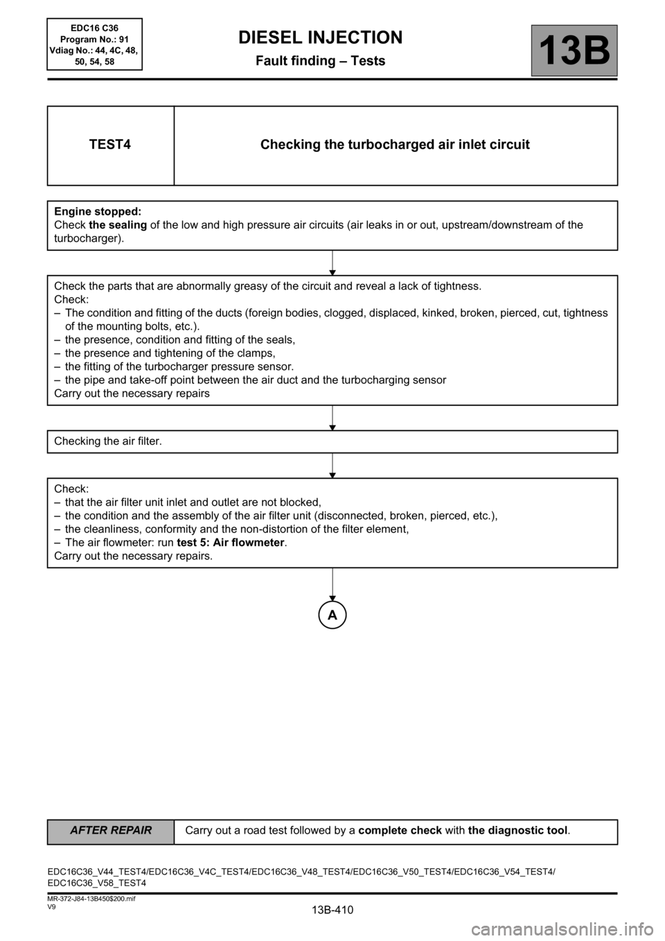
TEST4 Checking the turbocharged air inlet circuit
Engine stopped:
Check the sealing of the low and high pressure air circuits (air leaks in or out, upstream/downstream of the
turbocharger).
Check the parts that are abnormally greasy of the circuit and reveal a lack of tightness.
Check:
– The condition and fitting of the ducts (foreign bodies, clogged, displaced, kinked, broken, pierced, cut, tightness
of the mounting bolts, etc.).
– the presence, condition and fitting of the seals,
– the presence and tightening of the clamps,
– the fitting of the turbocharger pressure sensor.
– the pipe and take-off point between the air duct and the turbocharging sensor
Carry out the necessary repairs
Checking the air filter.
Check:
– that the air filter unit inlet and outlet are not blocked,
– the condition and the assembly of the air filter unit (disconnected, broken, pierced, etc.),
– the cleanliness, conformity and the non-distortion of the filter element,
– The air flowmeter: run test 5: Air flowmeter.
Carry out the necessary repairs.
A
EDC16C36_V44_TEST4/EDC16C36_V4C_TEST4/EDC16C36_V48_TEST4/EDC16C36_V50_TEST4/EDC16C36_V54_TEST4/
EDC16C36_V58_TEST4
AFTER REPAIRCarry out a road test followed by a complete check with the diagnostic tool.
EDC16 C36
Program No.: 91
Vdiag No.: 44, 4C, 48,
50, 54, 58
Page 411 of 431
13B-411V9 MR-372-J84-13B450$200.mif
DIESEL INJECTION
Fault finding – Tests13B
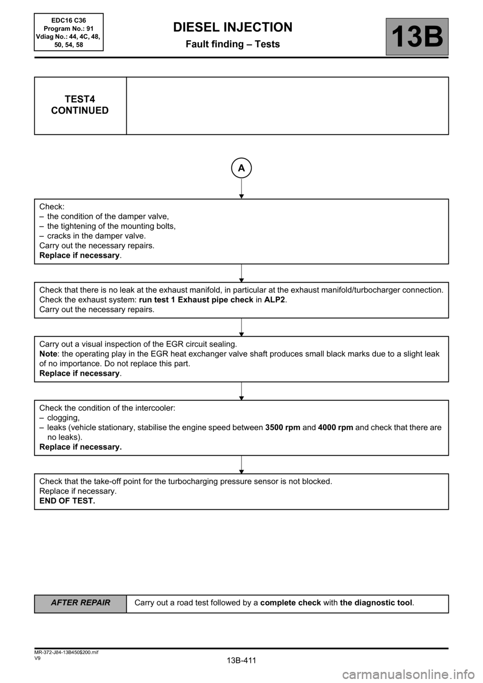
TEST4
CONTINUED
Check:
– the condition of the damper valve,
– the tightening of the mounting bolts,
– cracks in the damper valve.
Carry out the necessary repairs.
Replace if necessary.
Check that there is no leak at the exhaust manifold, in particular at the exhaust manifold/turbocharger connection.
Check the exhaust system: run test 1 Exhaust pipe check in ALP2.
Carry out the necessary repairs.
Carry out a visual inspection of the EGR circuit sealing.
Note: the operating play in the EGR heat exchanger valve shaft produces small black marks due to a slight leak
of no importance. Do not replace this part.
Replace if necessary.
Check the condition of the intercooler:
– clogging,
– leaks (vehicle stationary, stabilise the engine speed between 3500 rpm and 4000 rpm and check that there are
no leaks).
Replace if necessary.
Check that the take-off point for the turbocharging pressure sensor is not blocked.
Replace if necessary.
END OF TEST.
A
AFTER REPAIRCarry out a road test followed by a complete check with the diagnostic tool.
EDC16 C36
Program No.: 91
Vdiag No.: 44, 4C, 48,
50, 54, 58
Page 412 of 431
13B-412V9 MR-372-J84-13B450$200.mif
DIESEL INJECTION
Fault finding – Tests13B
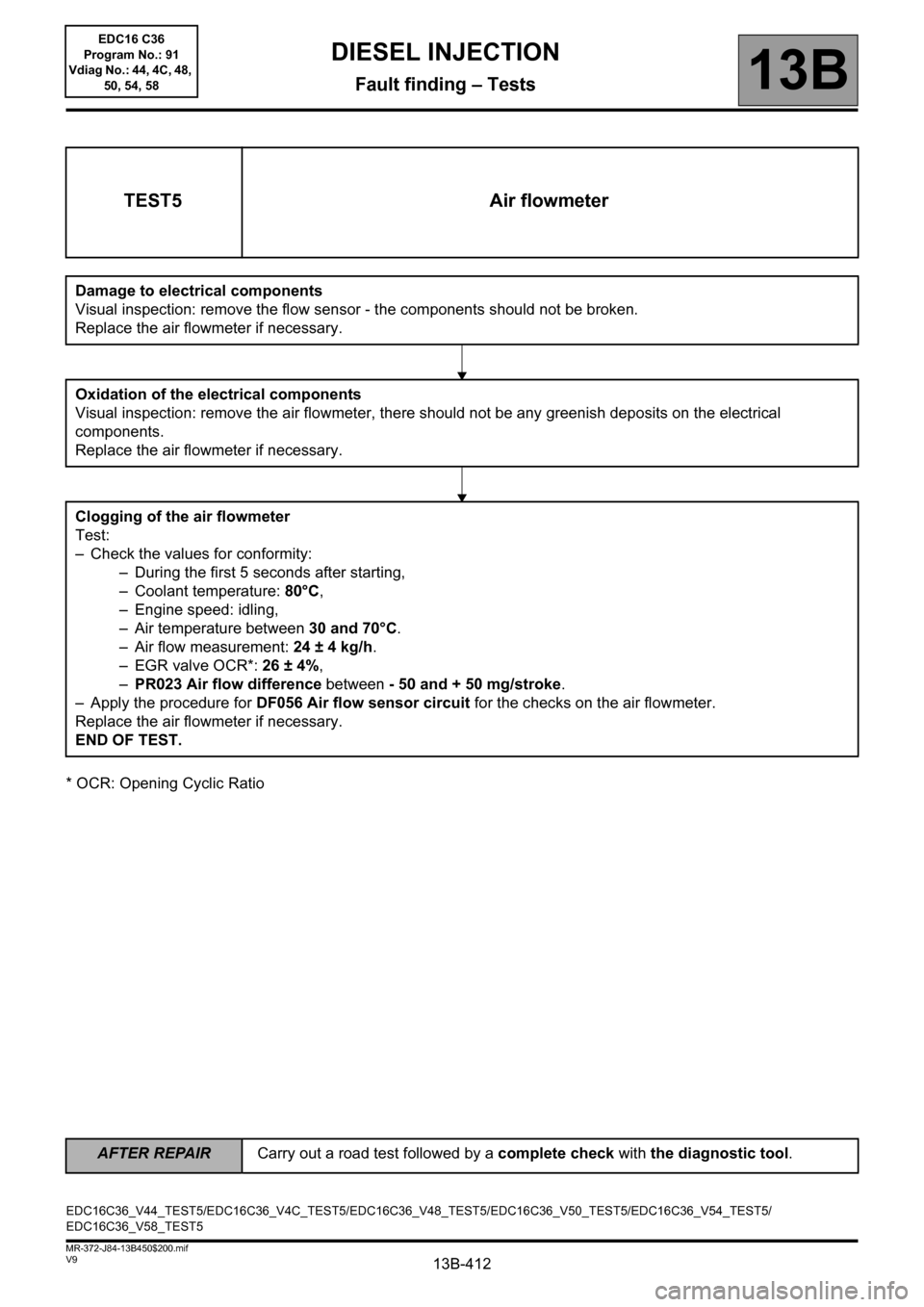
* OCR: Opening Cyclic Ratio
TEST5 Air flowmeter
Damage to electrical components
Visual inspection: remove the flow sensor - the components should not be broken.
Replace the air flowmeter if necessary.
Oxidation of the electrical components
Visual inspection: remove the air flowmeter, there should not be any greenish deposits on the electrical
components.
Replace the air flowmeter if necessary.
Clogging of the air flowmeter
Test:
– Check the values for conformity:
– During the first 5 seconds after starting,
– Coolant temperature: 80°C,
– Engine speed: idling,
– Air temperature between 30 and 70°C.
– Air flow measurement: 24 ± 4 kg/h.
– EGR valve OCR*: 26 ± 4%,
–PR023 Air flow difference between - 50 and + 50 mg/stroke.
– Apply the procedure for DF056 Air flow sensor circuit for the checks on the air flowmeter.
Replace the air flowmeter if necessary.
END OF TEST.
EDC16C36_V44_TEST5/EDC16C36_V4C_TEST5/EDC16C36_V48_TEST5/EDC16C36_V50_TEST5/EDC16C36_V54_TEST5/
EDC16C36_V58_TEST5
AFTER REPAIRCarry out a road test followed by a complete check with the diagnostic tool.
EDC16 C36
Program No.: 91
Vdiag No.: 44, 4C, 48,
50, 54, 58