ESP RENAULT SCENIC 2011 J95 / 3.G Engine And Peripherals EDC16C36 Workshop Manual
[x] Cancel search | Manufacturer: RENAULT, Model Year: 2011, Model line: SCENIC, Model: RENAULT SCENIC 2011 J95 / 3.GPages: 431, PDF Size: 2.03 MB
Page 3 of 431

13B-3V9 MR-372-J84-13B450$010.mif
DIESEL INJECTION
Fault finding – Introduction13B
EDC16 C36
Program No.: 91
Vdiag No.: 44, 4C, 48,
50, 54, 58
Faults
Faults are declared present or stored (depending on whether they appeared in a certain context and have
disappeared since, or whether they remain present but are not diagnosed within the current context).
The present or stored fault status must be considered, when the diagnostic tool is used after switching on the +
after ignition feed (without operating the system components).
For a present fault, apply the procedure described in the Interpretation of faults section.
For a stored fault, note the faults displayed and apply the Notes section.
If the fault is confirmed when the instructions are applied, the fault is present. Deal with the fault.
If the fault is not confirmed, check:
– the electrical lines which correspond to the fault,
– the connectors for this connection,
– the resistance of the faulty component,
– the condition of the wires.
Conformity check
The purpose of the conformity check is to check data that does not produce a fault on the diagnostic tool if the data
is inconsistent. Therefore, this stage is used to:
– carry out fault finding on faults that do not have a fault display, and which may correspond to a customer complaint.
– check that the system is operating correctly and that there is no risk of a fault recurring after repair.
The conformity check is a fault finding procedure carried out using the interpretation of statuses and parameters.
If a status does not function normally or a parameter is outside the permitted tolerance values, consult the
corresponding fault finding page (see interpretation of statuses and parameters).
Customer complaints - Fault finding chart
If the test with the diagnostic tool is OK but the customer complaint is still present, the fault should be dealt with by
customer complaints
A synopsis of the general procedure to follow is provided on the following page in the form of a flow chart.
Page 16 of 431

13B-16V9 MR-372-J84-13B450$050.mif
DIESEL INJECTION
Fault finding – Features13B
EDC16 C36
Program No.: 91
Vdiag No.: 44, 4C, 48,
50, 54, 58
The high pressure pump is supplied at low pressure by an integrated low pressure pump (transfer pump).
It supplies the rail, the pressure of which is controlled by the fuel flow actuator (MPROP) for charging, and for
discharging by the injector valves. This compensates for pressure drops. The flow actuator allows the high pressure
pump to supply the exact quantity of diesel fuel required to maintain the pressure in the rail. This component
minimises the heat generated and improves engine output. In order to discharge the rail using the injector valves,
the valves are controlled by brief electrical pulses which are:
– short enough not to open the injector (passing through the feedback circuit from the injectors),
– long enough to open the valves and discharge the rail.
Some vehicles have a presence sensor mounted in the filter for detecting water in the diesel. If there is water in the
diesel fuel, the orange “Injection and pre-post heating” warning light will come on.
The system can inject diesel fuel into the engine at a pressure of up to 1600 bar. Before each operation, check that
the injector rail is depressurised and that the fuel temperature is not too high.
You must respect the cleanliness guidelines and safety advice specified in this document for any work on the high
pressure injection system.
Removal of the internal parts of the pump and injectors is prohibited. Only the fuel flow regulator/actuator, diesel fuel
temperature sensor and the venturi can be replaced.
For safety reasons, it is strictly prohibited to undo a high pressure pipe union when the engine is running.
It is not possible to remove the pressure sensor from the fuel rail because this may cause circuit contamination
faults. If the pressure sensor is defective, replace the pressure sensor, rail and high pressure pipes associated with
the rail.
Supplying + 12 V directly to any component in the system is prohibited.
Ultrasonic decoking and cleaning are prohibited.
Never start the engine unless the battery is connected correctly.
Disconnect the injection computer when carrying out any welding work on the vehicle. WARNING
The engine must not operate with:
– Diesel fuel containing more than 10% diester,
– petrol, even in tiny quantities.
Page 30 of 431

13B-30V9 MR-372-J84-13B450$080.mif
DIESEL INJECTION
Fault finding – Replacement of components13B
EDC16 C36
Program No.: 91
Vdiag No.: 44, 4C, 48,
50, 54, 58
PROCEDURE:
Before replacing or reprogramming the computer:
–Select SC003 Save computer data,
– if the following message appears: a saved file exists; do you want to overwrite this data?: (this file corresponds
to the last save carried out on the tool)
–select "YES".
When the save has been performed, replace the computer or carry out the programming then proceed to the next
step.
After replacing or reprogramming the computer:
–Select SC001 Enter saved data, then follow the instructions given by the diagnostic tool,
– if the VIN is not entered (see Computer identification on the main screen),
–select VP010 Enter VIN,
When both these commands have finished:
– Switch off the ignition and wait for the diagnostic tool message (maximum time 8 minutes) Communication lost
with computer: EDC16 C36, check the tool connection and computer power supply before switching the
ignition back on.
(The powerlatch duration depends on the coolant temperature and activation time of the turbocharger
coolant pump. This operation finishes when the pump is deactivated.)
– then check the system faults, and clear any stored faults,
– if there are faults, deal with the present faults,
– clear the faults from the computer memory.
Carry out a road test followed by another check with the diagnostic tool.
End of the procedure.IMPORTANT
– The injection computer retains the immobiliser code for life.
– The system has no security code.
– It is forbidden to perform tests with computers borrowed from the Parts Department or from another vehicle
which must then be returned.
– These computers are hard-coded.
– If the injection computer appears to be faulty, contact the Techline and refer to the fault finding log.
Page 31 of 431

13B-31V9 MR-372-J84-13B450$080.mif
DIESEL INJECTION
Fault finding – Replacement of components13B
EDC16 C36
Program No.: 91
Vdiag No.: 44, 4C, 48,
50, 54, 58
REPLACING THE INJECTORS
After one or more injectors have been replaced, enter the IMA codes again and then run command SC036
Reinitialise programming.
The system must be configured via the diagnostic socket using the RENAULT CLIP diagnostic tool.
PROCEDURE to be followed after replacing one or more injectors:
– Note the "IMA" code(s) engraved on the injector bodies,
– enter these codes in the computer using command SC002 Enter injector codes, then follow the instructions given
by the diagnostic tool,
– once the command has finished,
–switch off the ignition and wait for the diagnostic tool message (maximum time 8 minutes) Communication
lost with computer: EDC16 C36, check the tool connection and computer power supply before switching the
ignition back on.
– Return to fault finding mode.
– select the Identify computer function from the main screen.
– check that the injector codes entered into the computer match those found on the bodies of the injectors:
– If the codes do not match, restart the command SC002 Enter injector codes procedure.
– If the codes correspond, run command SC036 Reinitialise programming,
–select Injectors as the type of operation, then follow the instructions given by the diagnostic tool.
– Then check the system faults, and clear any stored faults.
– if there are faults, deal with the present faults,
– clear the faults from the computer memory.
Carry out a road test followed by another check with the diagnostic tool.
End of the procedure.Note:
The IMA coding (individual injector correction) is a calibration made in production on each injector to adjust
the flow accurately.
These correction values are etched onto the Bakelite body of each injector (7 alphanumeric characters) and then
entered into the computer which then controls each injector taking into account its individual manufacturing
variation.
IMPORTANT
Cylinder no. 1 is located on the engine flywheel end.
IMPORTANT
Engines can only operate correctly if the correct IMA codes have been entered.
If no code has been entered, or if an implausible code has been entered, fault DF276 "Injector Code
Programming" will be present, and the engine will be in defect mode (engine speed is reduced
significantly).
If another injector's code has been entered, the system will accept it but will make the wrong correction.
This could lead to engine damage, loss of performance and excessive pollution.
Always use the correct injector codes for the engine cylinder/computer.
Page 40 of 431
13B-40V9 MR-372-J84-13B450$101.mif
13B
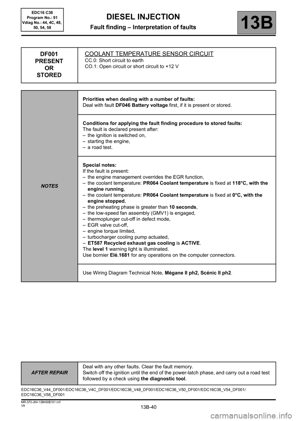
DF001
PRESENT
OR
STOREDCOOLANT TEMPERATURE SENSOR CIRCUIT
CC.0: Short circuit to earth
CO.1: Open circuit or short circuit to +12 V
NOTESPriorities when dealing with a number of faults:
Deal with fault DF046 Battery voltage first, if it is present or stored.
Conditions for applying the fault finding procedure to stored faults:
The fault is declared present after:
– the ignition is switched on,
– starting the engine,
– a road test.
Special notes:
If the fault is present:
– the engine management overrides the EGR function,
– the coolant temperature: PR064 Coolant temperature is fixed at 118°C, with the
engine running,
– the coolant temperature: PR064 Coolant temperature is fixed at 0°C, with the
engine stopped,
– the preheating phase is greater than 10 seconds,
– the low-speed fan assembly (GMV1) is engaged,
– thermoplunger cut-off in defect mode,
– EGR valve cut-off,
– engine torque limited,
– turbocharger cooling pump actuated,
–ET587 Recycled exhaust gas cooling is ACTIVE.
The level 1 warning light is illuminated.
Use bornier Elé.1681 for any operations on the computer connectors.
Use Wiring Diagram Technical Note, Mégane II ph2, Scénic II ph2.
EDC16C36_V44_DF001/EDC16C36_V4C_DF001/EDC16C36_V48_DF001/EDC16C36_V50_DF001/EDC16C36_V54_DF001/
EDC16C36_V58_DF001
DIESEL INJECTION
Fault finding – Interpretation of faults
AFTER REPAIRDeal with any other faults. Clear the fault memory.
Switch off the ignition until the end of the power-latch phase, and carry out a road test
followed by a check using the diagnostic tool.
EDC16 C36
Program No.: 91
Vdiag No.: 44, 4C, 48,
50, 54, 58
Page 43 of 431
13B-43V9 MR-372-J84-13B450$101.mif
DIESEL INJECTION
Fault finding – Interpretation of faults13B
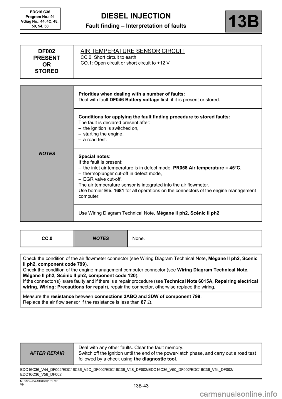
DF002
PRESENT
OR
STOREDAIR TEMPERATURE SENSOR CIRCUIT
CC.0: Short circuit to earth
CO.1: Open circuit or short circuit to +12 V
NOTESPriorities when dealing with a number of faults:
Deal with fault DF046 Battery voltage first, if it is present or stored.
Conditions for applying the fault finding procedure to stored faults:
The fault is declared present after:
– the ignition is switched on,
– starting the engine,
– a road test.
Special notes:
If the fault is present:
– the inlet air temperature is in defect mode, PR058 Air temperature =45°C.
– thermoplunger cut-off in defect mode,
– EGR valve cut-off,
The air temperature sensor is integrated into the air flowmeter.
Use bornier Elé. 1681 for all operations on the connectors of the engine management
computer.
Use Wiring Diagram Technical Note, Mégane II ph2, Scénic II ph2.
CC.0
NOTESNone.
Check the condition of the air flowmeter connector (see Wiring Diagram Technical Note, Mégane II ph2, Scenic
II ph2, component code 799).
Check the condition of the engine management computer connector (see Wiring Diagram Technical Note,
Mégane II ph2, Scénic II ph2, component code 120).
If the connector(s) is/are faulty and if there is a repair procedure (see Technical Note 6015A, Repairing electrical
wiring, Wiring: Precautions for repair), repair the connector, otherwise replace the wiring.
Measure the resistance between connections 3ABQ and 3DW of component 799.
Replace the air flow sensor if the resistance is less than 87Ω.
EDC16C36_V44_DF002/EDC16C36_V4C_DF002/EDC16C36_V48_DF002/EDC16C36_V50_DF002/EDC16C36_V54_DF002/
EDC16C36_V58_DF002
AFTER REPAIRDeal with any other faults. Clear the fault memory.
Switch off the ignition until the end of the power-latch phase, and carry out a road test
followed by a check using the diagnostic tool.
EDC16 C36
Program No.: 91
Vdiag No.: 44, 4C, 48,
50, 54, 58
Page 45 of 431
13B-45V9 MR-372-J84-13B450$101.mif
DIESEL INJECTION
Fault finding – Interpretation of faults13B
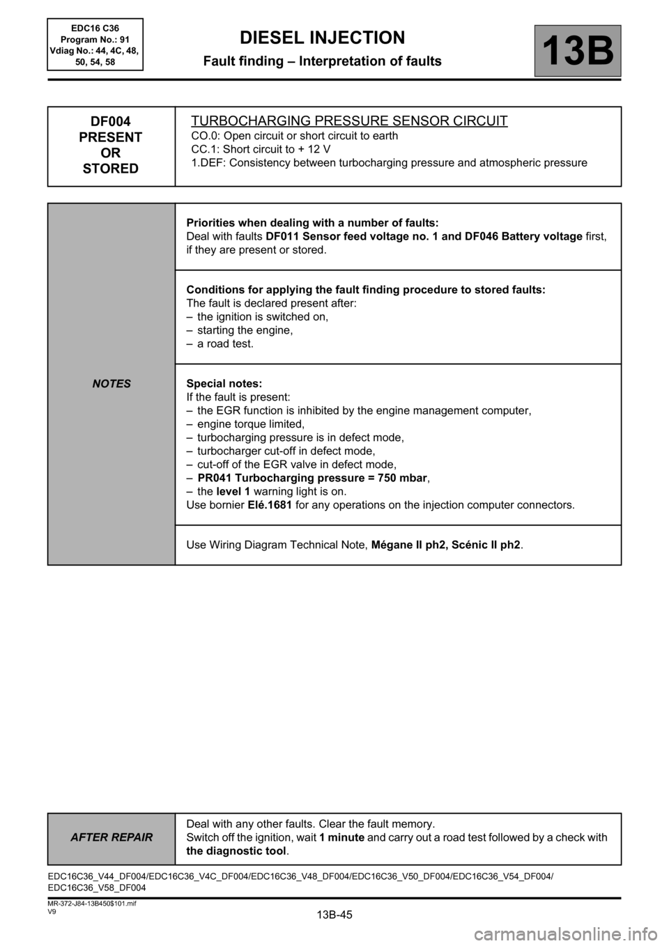
DF004
PRESENT
OR
STOREDTURBOCHARGING PRESSURE SENSOR CIRCUIT
CO.0: Open circuit or short circuit to earth
CC.1: Short circuit to + 12 V
1.DEF: Consistency between turbocharging pressure and atmospheric pressure
NOTESPriorities when dealing with a number of faults:
Deal with faults DF011 Sensor feed voltage no. 1 and DF046 Battery voltage first,
if they are present or stored.
Conditions for applying the fault finding procedure to stored faults:
The fault is declared present after:
– the ignition is switched on,
– starting the engine,
– a road test.
Special notes:
If the fault is present:
– the EGR function is inhibited by the engine management computer,
– engine torque limited,
– turbocharging pressure is in defect mode,
– turbocharger cut-off in defect mode,
– cut-off of the EGR valve in defect mode,
–PR041 Turbocharging pressure = 750 mbar,
–the level 1 warning light is on.
Use bornier Elé.1681 for any operations on the injection computer connectors.
Use Wiring Diagram Technical Note, Mégane II ph2, Scénic II ph2.
EDC16C36_V44_DF004/EDC16C36_V4C_DF004/EDC16C36_V48_DF004/EDC16C36_V50_DF004/EDC16C36_V54_DF004/
EDC16C36_V58_DF004
AFTER REPAIRDeal with any other faults. Clear the fault memory.
Switch off the ignition, wait 1 minute and carry out a road test followed by a check with
the diagnostic tool.
EDC16 C36
Program No.: 91
Vdiag No.: 44, 4C, 48,
50, 54, 58
Page 48 of 431
13B-48V9 MR-372-J84-13B450$101.mif
DIESEL INJECTION
Fault finding – Interpretation of faults13B
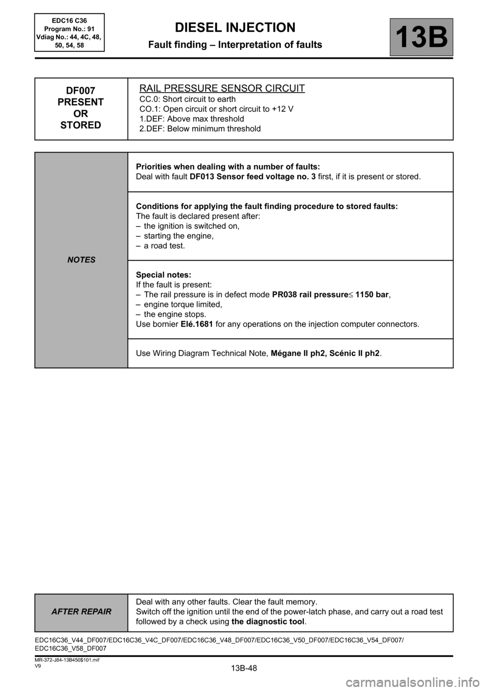
DF007
PRESENT
OR
STOREDRAIL PRESSURE SENSOR CIRCUITCC.0: Short circuit to earth
CO.1: Open circuit or short circuit to +12 V
1.DEF: Above max threshold
2.DEF: Below minimum threshold
NOTESPriorities when dealing with a number of faults:
Deal with fault DF013 Sensor feed voltage no. 3 first, if it is present or stored.
Conditions for applying the fault finding procedure to stored faults:
The fault is declared present after:
– the ignition is switched on,
– starting the engine,
– a road test.
Special notes:
If the fault is present:
– The rail pressure is in defect mode PR038 rail pressure≤ 1150 bar,
– engine torque limited,
– the engine stops.
Use bornier Elé.1681 for any operations on the injection computer connectors.
Use Wiring Diagram Technical Note, Mégane II ph2, Scénic II ph2.
EDC16C36_V44_DF007/EDC16C36_V4C_DF007/EDC16C36_V48_DF007/EDC16C36_V50_DF007/EDC16C36_V54_DF007/
EDC16C36_V58_DF007
AFTER REPAIRDeal with any other faults. Clear the fault memory.
Switch off the ignition until the end of the power-latch phase, and carry out a road test
followed by a check using the diagnostic tool.
EDC16 C36
Program No.: 91
Vdiag No.: 44, 4C, 48,
50, 54, 58
Page 64 of 431
13B-64V9 MR-372-J84-13B450$101.mif
DIESEL INJECTION
Fault finding – Interpretation of faults13B
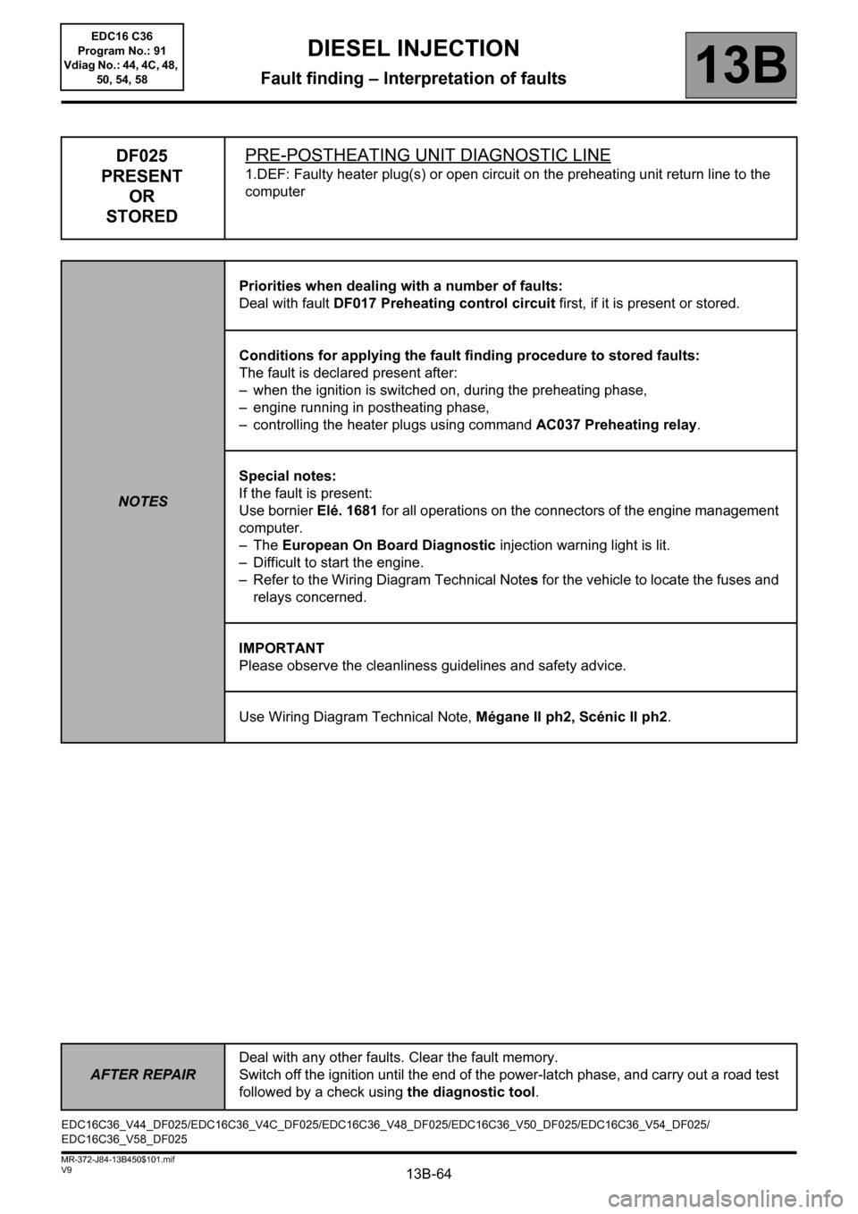
DF025
PRESENT
OR
STOREDPRE-POSTHEATING UNIT DIAGNOSTIC LINE
1.DEF: Faulty heater plug(s) or open circuit on the preheating unit return line to the
computer
NOTESPriorities when dealing with a number of faults:
Deal with fault DF017 Preheating control circuit first, if it is present or stored.
Conditions for applying the fault finding procedure to stored faults:
The fault is declared present after:
– when the ignition is switched on, during the preheating phase,
– engine running in postheating phase,
– controlling the heater plugs using command AC037 Preheating relay.
Special notes:
If the fault is present:
Use bornier Elé. 1681 for all operations on the connectors of the engine management
computer.
–The European On Board Diagnostic injection warning light is lit.
– Difficult to start the engine.
– Refer to the Wiring Diagram Technical Notes for the vehicle to locate the fuses and
relays concerned.
IMPORTANT
Please observe the cleanliness guidelines and safety advice.
Use Wiring Diagram Technical Note, Mégane II ph2, Scénic II ph2.
EDC16C36_V44_DF025/EDC16C36_V4C_DF025/EDC16C36_V48_DF025/EDC16C36_V50_DF025/EDC16C36_V54_DF025/
EDC16C36_V58_DF025
AFTER REPAIRDeal with any other faults. Clear the fault memory.
Switch off the ignition until the end of the power-latch phase, and carry out a road test
followed by a check using the diagnostic tool.
EDC16 C36
Program No.: 91
Vdiag No.: 44, 4C, 48,
50, 54, 58
Page 81 of 431
13B-81V9 MR-372-J84-13B450$102.mif
DIESEL INJECTION
Fault finding – Interpretation of faults13B
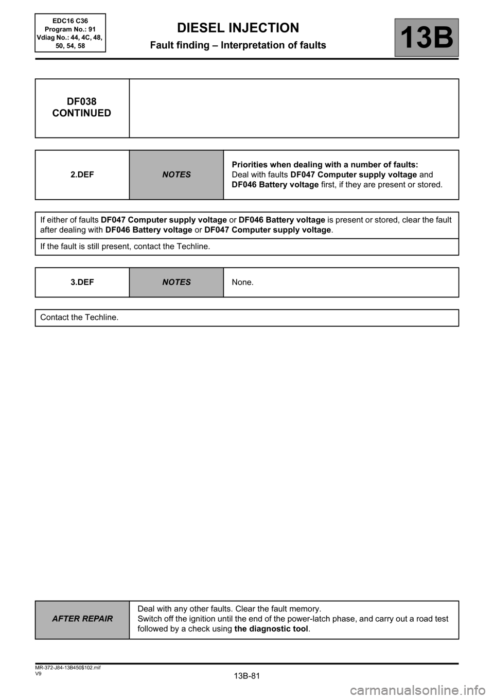
DF038
CONTINUED
2.DEFNOTESPriorities when dealing with a number of faults:
Deal with faults DF047 Computer supply voltage and
DF046 Battery voltage first, if they are present or stored.
If either of faults DF047 Computer supply voltage or DF046 Battery voltage is present or stored, clear the fault
after dealing with DF046 Battery voltage or DF047 Computer supply voltage.
If the fault is still present, contact the Techline.
3.DEF
NOTESNone.
Contact the Techline.
AFTER REPAIRDeal with any other faults. Clear the fault memory.
Switch off the ignition until the end of the power-latch phase, and carry out a road test
followed by a check using the diagnostic tool.
EDC16 C36
Program No.: 91
Vdiag No.: 44, 4C, 48,
50, 54, 58