check engine light RENAULT SCENIC 2011 J95 / 3.G Engine And Peripherals EDC16C36 Workshop Manual
[x] Cancel search | Manufacturer: RENAULT, Model Year: 2011, Model line: SCENIC, Model: RENAULT SCENIC 2011 J95 / 3.GPages: 431, PDF Size: 2.03 MB
Page 16 of 431

13B-16V9 MR-372-J84-13B450$050.mif
DIESEL INJECTION
Fault finding – Features13B
EDC16 C36
Program No.: 91
Vdiag No.: 44, 4C, 48,
50, 54, 58
The high pressure pump is supplied at low pressure by an integrated low pressure pump (transfer pump).
It supplies the rail, the pressure of which is controlled by the fuel flow actuator (MPROP) for charging, and for
discharging by the injector valves. This compensates for pressure drops. The flow actuator allows the high pressure
pump to supply the exact quantity of diesel fuel required to maintain the pressure in the rail. This component
minimises the heat generated and improves engine output. In order to discharge the rail using the injector valves,
the valves are controlled by brief electrical pulses which are:
– short enough not to open the injector (passing through the feedback circuit from the injectors),
– long enough to open the valves and discharge the rail.
Some vehicles have a presence sensor mounted in the filter for detecting water in the diesel. If there is water in the
diesel fuel, the orange “Injection and pre-post heating” warning light will come on.
The system can inject diesel fuel into the engine at a pressure of up to 1600 bar. Before each operation, check that
the injector rail is depressurised and that the fuel temperature is not too high.
You must respect the cleanliness guidelines and safety advice specified in this document for any work on the high
pressure injection system.
Removal of the internal parts of the pump and injectors is prohibited. Only the fuel flow regulator/actuator, diesel fuel
temperature sensor and the venturi can be replaced.
For safety reasons, it is strictly prohibited to undo a high pressure pipe union when the engine is running.
It is not possible to remove the pressure sensor from the fuel rail because this may cause circuit contamination
faults. If the pressure sensor is defective, replace the pressure sensor, rail and high pressure pipes associated with
the rail.
Supplying + 12 V directly to any component in the system is prohibited.
Ultrasonic decoking and cleaning are prohibited.
Never start the engine unless the battery is connected correctly.
Disconnect the injection computer when carrying out any welding work on the vehicle. WARNING
The engine must not operate with:
– Diesel fuel containing more than 10% diester,
– petrol, even in tiny quantities.
Page 17 of 431

13B-17V9 MR-372-J84-13B450$050.mif
DIESEL INJECTION
Fault finding – Features13B
EDC16 C36
Program No.: 91
Vdiag No.: 44, 4C, 48,
50, 54, 58
a. The computer:
Determines the value of injection pressure necessary for the engine to operate correctly and then controls the
pressure regulator.
Checks that the pressure value is correct by analysing the value transmitted by the pressure sensor located on the
rail.
It determines the injection timing required to deliver the right quantity of diesel fuel and the moment when injection
should start. Controls each injector electrically and individually after determining these two values.
The flow injected into the engine is determined by:
– the duration of injector control,
– the rail pressure (regulated by the computer),
– the injector opening and closing speed,
– the needle stroke (determined by a constant for the type of injector),
– the nominal hydraulic flow of the injector (specific to each injector).
The computer manages:
– idling regulation,
– exhaust gas flow reinjection to the inlet (EGR),
– fuel supply check (advance, flow and rail pressure),
– the fan assembly control,
– the air conditioning (cold loop function),
– the cruise control/speed limiter function,
– pre-post heating control,
– indicator lights control via the multiplex network,
– the catalysed particle filter operation (F9Q816 engine only).
Page 23 of 431

13B-23V9 MR-372-J84-13B450$050.mif
DIESEL INJECTION
Fault finding – Features13B
EDC16 C36
Program No.: 91
Vdiag No.: 44, 4C, 48,
50, 54, 58
Orange pre-postheating warning light
This warning light is used as an in-operation indicator lamp:
– Continuously lit under + after ignition feed: indicates preheating of the heater plugs.
It goes out when preheating is complete and the engine is able to start.
Orange "SERVICE" non-critical fault warning light (level 1)
This warning light is used to indicate a fault in the system:
– Continuously lit with the CHECK INJECTION message:
Indicates a level 1 fault (involving operation of the injection system in defect mode).
The driver should have the repairs carried out as soon as possible.
Temperature/red emergency STOP (level 2) warning light
This indicator light is used both as an in-operation indicator light and as a system fault warning light.
– Intermittently lit with the ENGINE OVERHEATING message:
Indicates that the coolant temperature is too high (the driver is free to stop the vehicle or not).
– Continuously lit with the INJECTION FAULT: STOP THE ENGINE message and an audible beep indicates a level
2 fault.
In that case, the vehicle must be stopped immediately (when traffic conditions allow).
The driver should carry out repairs as soon as possible.
European On Board Diagnostic excess pollution ORANGE warning light
Engine symbol with the CHECK EMISSION CONTROL message.
This warning light comes on if the system has one or more OBD faults.
This warning light is used to alert the driver to injection faults that could lead to excessive pollution, or if the EOBD
system (European On Board Diagnostic) has been deactivated.
The injection computer requests illumination of the OBD warning light for a present fault only after three successive
driving cycles.
The driver should have the repairs carried out as soon as possible.
Page 40 of 431
13B-40V9 MR-372-J84-13B450$101.mif
13B
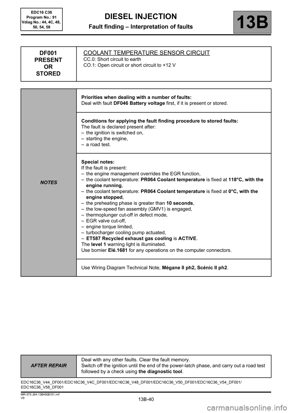
DF001
PRESENT
OR
STOREDCOOLANT TEMPERATURE SENSOR CIRCUIT
CC.0: Short circuit to earth
CO.1: Open circuit or short circuit to +12 V
NOTESPriorities when dealing with a number of faults:
Deal with fault DF046 Battery voltage first, if it is present or stored.
Conditions for applying the fault finding procedure to stored faults:
The fault is declared present after:
– the ignition is switched on,
– starting the engine,
– a road test.
Special notes:
If the fault is present:
– the engine management overrides the EGR function,
– the coolant temperature: PR064 Coolant temperature is fixed at 118°C, with the
engine running,
– the coolant temperature: PR064 Coolant temperature is fixed at 0°C, with the
engine stopped,
– the preheating phase is greater than 10 seconds,
– the low-speed fan assembly (GMV1) is engaged,
– thermoplunger cut-off in defect mode,
– EGR valve cut-off,
– engine torque limited,
– turbocharger cooling pump actuated,
–ET587 Recycled exhaust gas cooling is ACTIVE.
The level 1 warning light is illuminated.
Use bornier Elé.1681 for any operations on the computer connectors.
Use Wiring Diagram Technical Note, Mégane II ph2, Scénic II ph2.
EDC16C36_V44_DF001/EDC16C36_V4C_DF001/EDC16C36_V48_DF001/EDC16C36_V50_DF001/EDC16C36_V54_DF001/
EDC16C36_V58_DF001
DIESEL INJECTION
Fault finding – Interpretation of faults
AFTER REPAIRDeal with any other faults. Clear the fault memory.
Switch off the ignition until the end of the power-latch phase, and carry out a road test
followed by a check using the diagnostic tool.
EDC16 C36
Program No.: 91
Vdiag No.: 44, 4C, 48,
50, 54, 58
Page 45 of 431
13B-45V9 MR-372-J84-13B450$101.mif
DIESEL INJECTION
Fault finding – Interpretation of faults13B
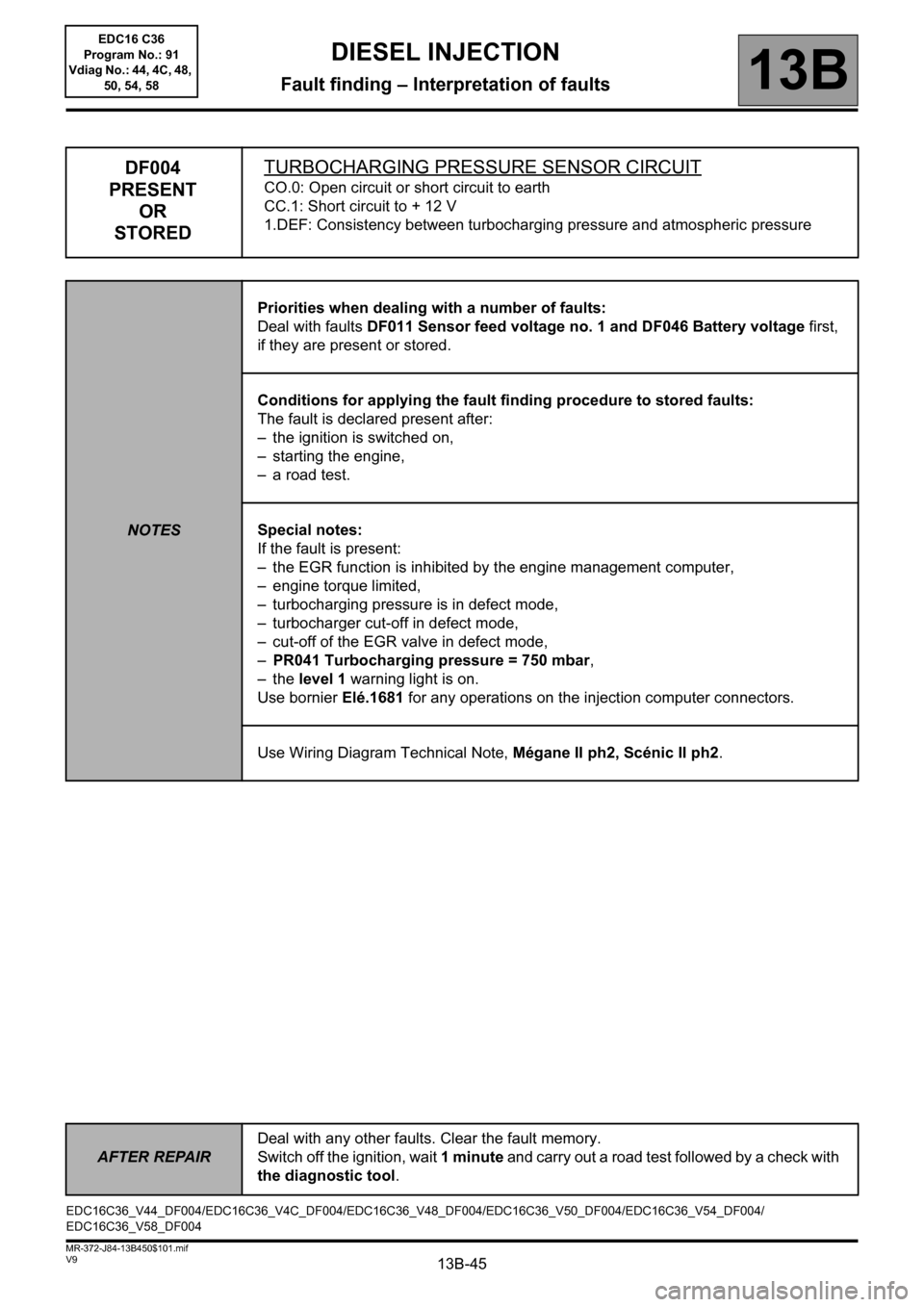
DF004
PRESENT
OR
STOREDTURBOCHARGING PRESSURE SENSOR CIRCUIT
CO.0: Open circuit or short circuit to earth
CC.1: Short circuit to + 12 V
1.DEF: Consistency between turbocharging pressure and atmospheric pressure
NOTESPriorities when dealing with a number of faults:
Deal with faults DF011 Sensor feed voltage no. 1 and DF046 Battery voltage first,
if they are present or stored.
Conditions for applying the fault finding procedure to stored faults:
The fault is declared present after:
– the ignition is switched on,
– starting the engine,
– a road test.
Special notes:
If the fault is present:
– the EGR function is inhibited by the engine management computer,
– engine torque limited,
– turbocharging pressure is in defect mode,
– turbocharger cut-off in defect mode,
– cut-off of the EGR valve in defect mode,
–PR041 Turbocharging pressure = 750 mbar,
–the level 1 warning light is on.
Use bornier Elé.1681 for any operations on the injection computer connectors.
Use Wiring Diagram Technical Note, Mégane II ph2, Scénic II ph2.
EDC16C36_V44_DF004/EDC16C36_V4C_DF004/EDC16C36_V48_DF004/EDC16C36_V50_DF004/EDC16C36_V54_DF004/
EDC16C36_V58_DF004
AFTER REPAIRDeal with any other faults. Clear the fault memory.
Switch off the ignition, wait 1 minute and carry out a road test followed by a check with
the diagnostic tool.
EDC16 C36
Program No.: 91
Vdiag No.: 44, 4C, 48,
50, 54, 58
Page 49 of 431
13B-49V9 MR-372-J84-13B450$101.mif
DIESEL INJECTION
Fault finding – Interpretation of faults13B
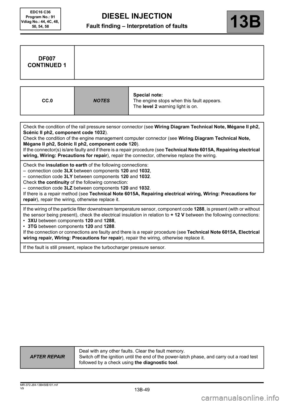
DF007
CONTINUED 1
CC.0NOTESSpecial note:
The engine stops when this fault appears.
The level 2 warning light is on.
Check the condition of the rail pressure sensor connector (see Wiring Diagram Technical Note, Mégane II ph2,
Scénic II ph2, component code 1032).
Check the condition of the engine management computer connector (see Wiring Diagram Technical Note,
Mégane II ph2, Scénic II ph2, component code 120).
If the connector(s) is/are faulty and if there is a repair procedure (see Technical Note 6015A, Repairing electrical
wiring, Wiring: Precautions for repair), repair the connector, otherwise replace the wiring.
Check the insulation to earth of the following connections:
– connection code 3LX between components 120 and 1032,
– connection code 3LY between components 120 and 1032.
Check the continuity of the following connection:
– connection code 3LZ between components 120 and 1032.
If there is a repair method (see Technical Note 6015A, Repairing electrical wiring, Wiring: Precautions for
repair), repair the wiring, otherwise replace it.
If the wiring of the particle filter downstream temperature sensor, component code 1288, is present (with or without
the sensor being present), check the electrical insulation in relation to + 12 V between the following connections:
•3XU between components 120 and 1288,
•3TG between components 120 and 1288.
If the connection or connections are faulty and there is a repair procedure (see Technical Note 6015A, Electrical
wiring repair, Wiring: Precautions for repair), repair the wiring, otherwise replace it.
If the fault is still present, replace the turbocharger pressure sensor.
AFTER REPAIRDeal with any other faults. Clear the fault memory.
Switch off the ignition until the end of the power-latch phase, and carry out a road test
followed by a check using the diagnostic tool.
EDC16 C36
Program No.: 91
Vdiag No.: 44, 4C, 48,
50, 54, 58
Page 50 of 431
13B-50V9 MR-372-J84-13B450$101.mif
DIESEL INJECTION
Fault finding – Interpretation of faults13B
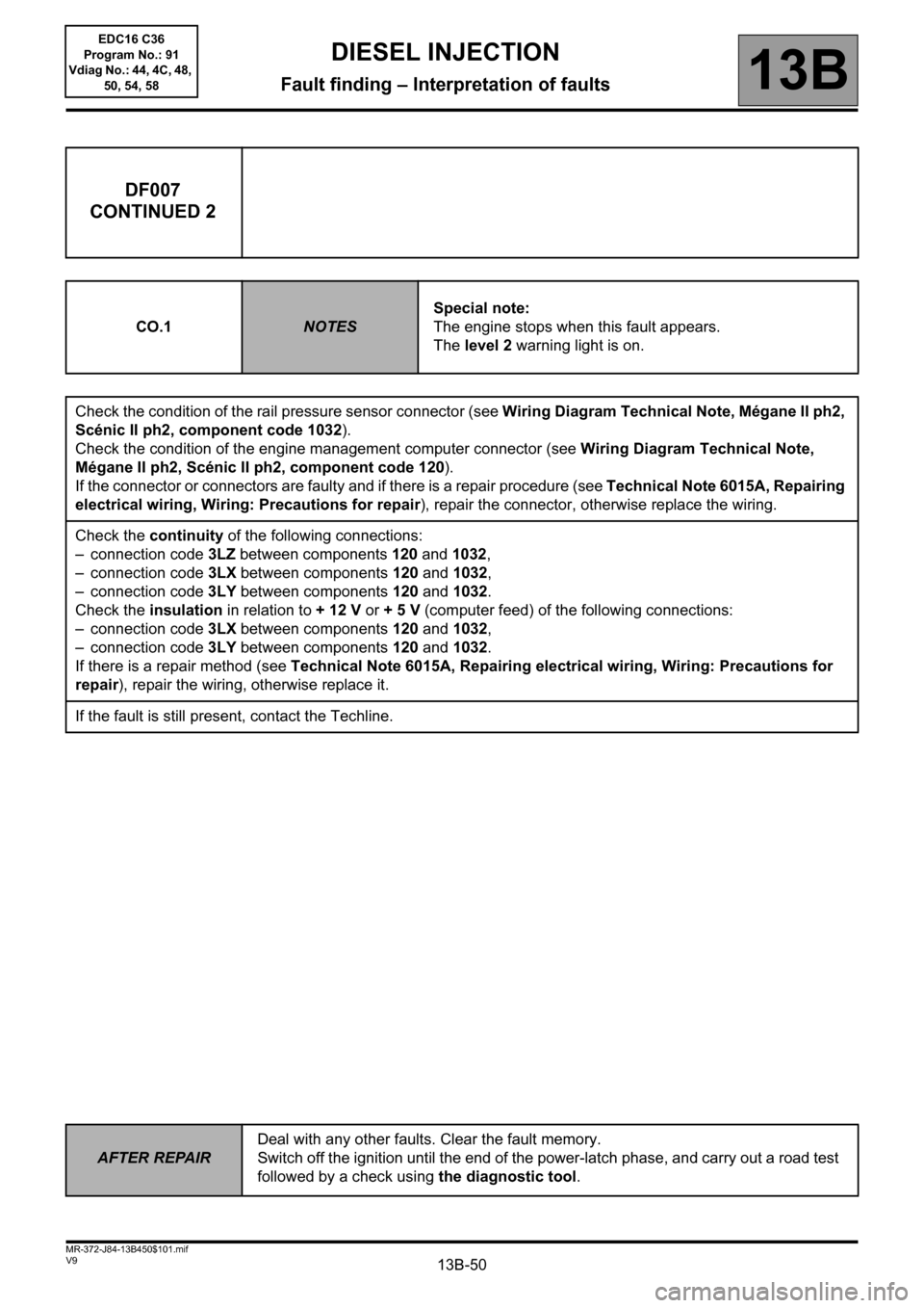
DF007
CONTINUED 2
CO.1NOTESSpecial note:
The engine stops when this fault appears.
The level 2 warning light is on.
Check the condition of the rail pressure sensor connector (see Wiring Diagram Technical Note, Mégane II ph2,
Scénic II ph2, component code 1032).
Check the condition of the engine management computer connector (see Wiring Diagram Technical Note,
Mégane II ph2, Scénic II ph2, component code 120).
If the connector or connectors are faulty and if there is a repair procedure (see Technical Note 6015A, Repairing
electrical wiring, Wiring: Precautions for repair), repair the connector, otherwise replace the wiring.
Check the continuity of the following connections:
– connection code 3LZ between components 120 and 1032,
– connection code 3LX between components 120 and 1032,
– connection code 3LY between components 120 and 1032.
Check the insulation in relation to + 12 V or + 5 V (computer feed) of the following connections:
– connection code 3LX between components 120 and 1032,
– connection code 3LY between components 120 and 1032.
If there is a repair method (see Technical Note 6015A, Repairing electrical wiring, Wiring: Precautions for
repair), repair the wiring, otherwise replace it.
If the fault is still present, contact the Techline.
AFTER REPAIRDeal with any other faults. Clear the fault memory.
Switch off the ignition until the end of the power-latch phase, and carry out a road test
followed by a check using the diagnostic tool.
EDC16 C36
Program No.: 91
Vdiag No.: 44, 4C, 48,
50, 54, 58
Page 51 of 431
13B-51V9 MR-372-J84-13B450$101.mif
DIESEL INJECTION
Fault finding – Interpretation of faults13B
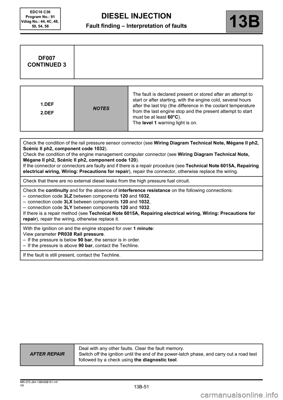
DF007
CONTINUED 3
1.DEF
2.DEFNOTESThe fault is declared present or stored after an attempt to
start or after starting, with the engine cold, several hours
after the last trip (the difference in the coolant temperature
from the last engine stop and the present attempt to start
must be at least 60°C).
The level 1 warning light is on.
Check the condition of the rail pressure sensor connector (see Wiring Diagram Technical Note, Mégane II ph2,
Scénic II ph2, component code 1032).
Check the condition of the engine management computer connector (see Wiring Diagram Technical Note,
Mégane II ph2, Scénic II ph2, component code 120).
If the connector or connectors are faulty and if there is a repair procedure (see Technical Note 6015A, Repairing
electrical wiring, Wiring: Precautions for repair), repair the connector, otherwise replace the wiring.
Check that there are no external diesel leaks from the high pressure fuel circuit.
Check the continuity and for the absence of interference resistance on the following connections:
– connection code 3LZ between components 120 and 1032,
– connection code 3LX between components 120 and 1032,
– connection code 3LY between components 120 and 1032.
If there is a repair method (see Technical Note 6015A, Repairing electrical wiring, Wiring: Precautions for
repair), repair the wiring, otherwise replace it.
With the ignition on and the engine stopped for over 1 minute:
View parameter PR038 Rail pressure.
– If the pressure is below 90 bar, the sensor is in order.
– If the pressure is above 90 bar, contact the Techline.
If the fault is still present, contact the Techline.
AFTER REPAIRDeal with any other faults. Clear the fault memory.
Switch off the ignition until the end of the power-latch phase, and carry out a road test
followed by a check using the diagnostic tool.
EDC16 C36
Program No.: 91
Vdiag No.: 44, 4C, 48,
50, 54, 58
Page 52 of 431
13B-52V9 MR-372-J84-13B450$101.mif
DIESEL INJECTION
Fault finding – Interpretation of faults13B
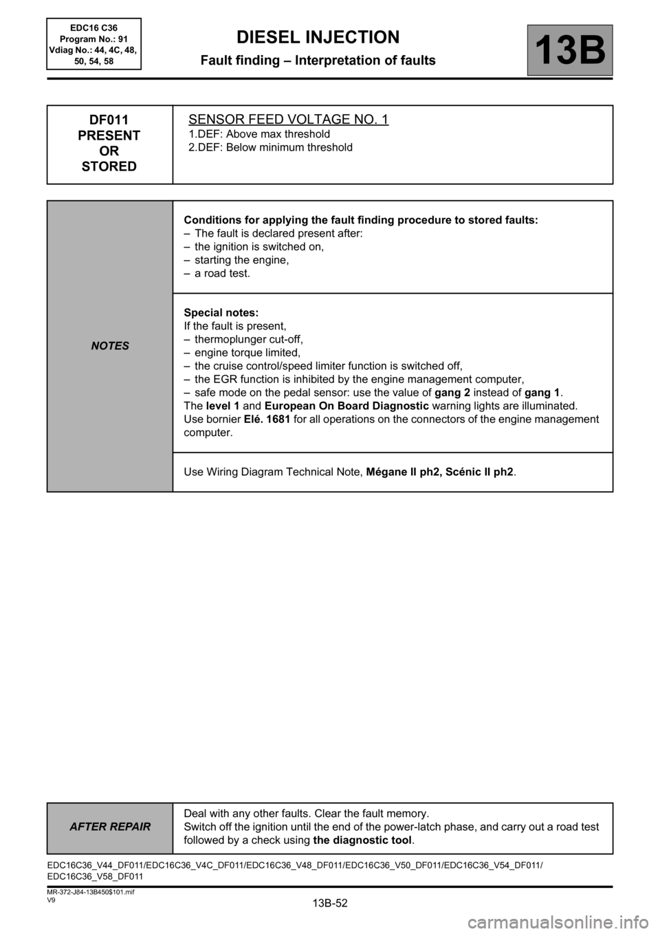
DF011
PRESENT
OR
STOREDSENSOR FEED VOLTAGE NO. 1
1.DEF: Above max threshold
2.DEF: Below minimum threshold
NOTESConditions for applying the fault finding procedure to stored faults:
– The fault is declared present after:
– the ignition is switched on,
– starting the engine,
– a road test.
Special notes:
If the fault is present,
– thermoplunger cut-off,
– engine torque limited,
– the cruise control/speed limiter function is switched off,
– the EGR function is inhibited by the engine management computer,
– safe mode on the pedal sensor: use the value of gang 2 instead of gang 1.
The level 1 and European On Board Diagnostic warning lights are illuminated.
Use bornier Elé. 1681 for all operations on the connectors of the engine management
computer.
Use Wiring Diagram Technical Note, Mégane II ph2, Scénic II ph2.
EDC16C36_V44_DF011/EDC16C36_V4C_DF011/EDC16C36_V48_DF011/EDC16C36_V50_DF011/EDC16C36_V54_DF011/
EDC16C36_V58_DF011
AFTER REPAIRDeal with any other faults. Clear the fault memory.
Switch off the ignition until the end of the power-latch phase, and carry out a road test
followed by a check using the diagnostic tool.
EDC16 C36
Program No.: 91
Vdiag No.: 44, 4C, 48,
50, 54, 58
Page 55 of 431
13B-55V9 MR-372-J84-13B450$101.mif
DIESEL INJECTION
Fault finding – Interpretation of faults13B
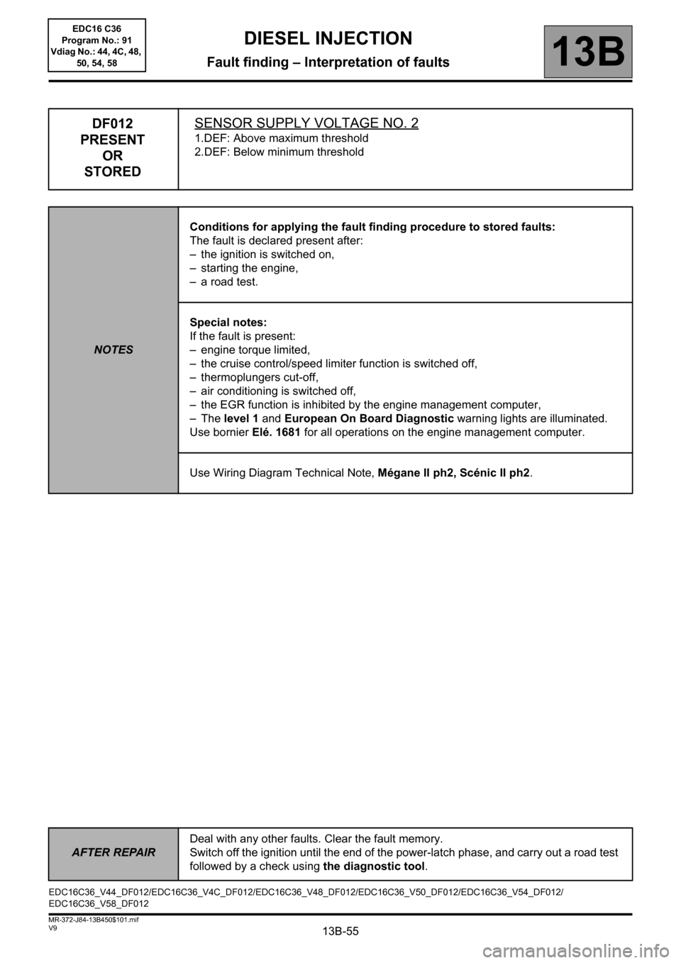
DF012
PRESENT
OR
STOREDSENSOR SUPPLY VOLTAGE NO. 2
1.DEF: Above maximum threshold
2.DEF: Below minimum threshold
NOTESConditions for applying the fault finding procedure to stored faults:
The fault is declared present after:
– the ignition is switched on,
– starting the engine,
– a road test.
Special notes:
If the fault is present:
– engine torque limited,
– the cruise control/speed limiter function is switched off,
– thermoplungers cut-off,
– air conditioning is switched off,
– the EGR function is inhibited by the engine management computer,
–The level 1 and European On Board Diagnostic warning lights are illuminated.
Use bornier Elé. 1681 for all operations on the engine management computer.
Use Wiring Diagram Technical Note, Mégane II ph2, Scénic II ph2.
EDC16C36_V44_DF012/EDC16C36_V4C_DF012/EDC16C36_V48_DF012/EDC16C36_V50_DF012/EDC16C36_V54_DF012/
EDC16C36_V58_DF012
AFTER REPAIRDeal with any other faults. Clear the fault memory.
Switch off the ignition until the end of the power-latch phase, and carry out a road test
followed by a check using the diagnostic tool.
EDC16 C36
Program No.: 91
Vdiag No.: 44, 4C, 48,
50, 54, 58