sensor RENAULT SCENIC 2011 J95 / 3.G Engine And Peripherals Siemens Injection Workshop Manual
[x] Cancel search | Manufacturer: RENAULT, Model Year: 2011, Model line: SCENIC, Model: RENAULT SCENIC 2011 J95 / 3.GPages: 329, PDF Size: 1.71 MB
Page 245 of 329
13B-245
MR-372-J84-13B050$780.mif
V17
DIESEL INJECTION
Fault finding – Interpretation of parameters
Siemens Injection
SID301 and 304
Vdiag No.: 44-45-48-49-4D-4C
Program No.: B1 and B2
13B
*temp: temperature
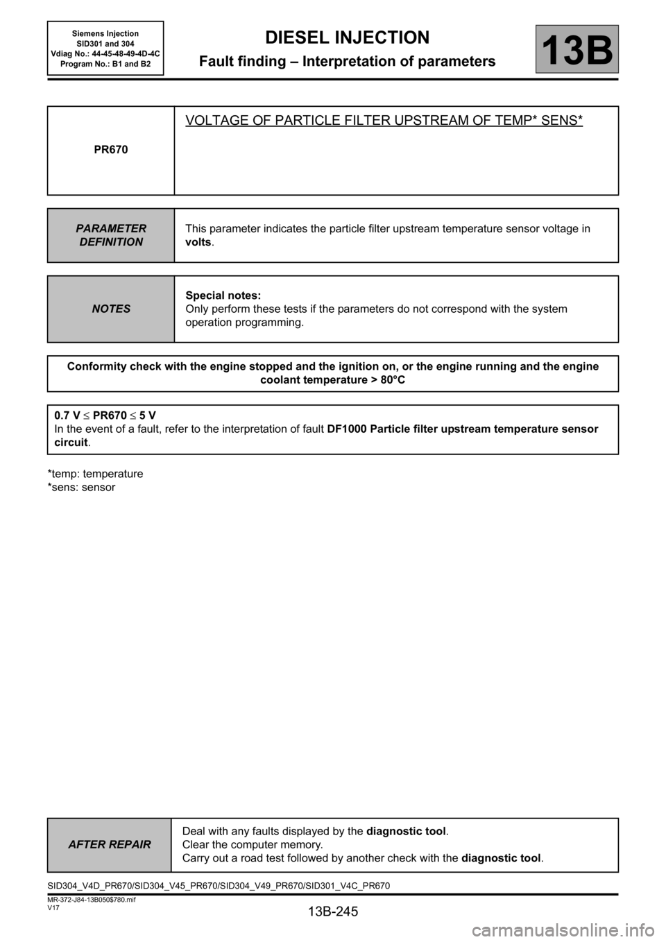
*sens: sensorPR670
VOLTAGE OF PARTICLE FILTER UPSTREAM OF TEMP* SENS*
PARAMETER
DEFINITIONThis parameter indicates the particle filter upstream temperature sensor voltage in
volts.
NOTESSpecial notes:
Only perform these tests if the parameters do not correspond with the system
operation programming.
Conformity check with the engine stopped and the ignition on, or the engine running and the engine
coolant temperature > 80°C
0.7 V ≤PR670 ≤5V
In the event of a fault, refer to the interpretation of fault DF1000 Particle filter upstream temperature sensor
circuit.
AFTER REPAIRDeal with any faults displayed by the diagnostic tool.
Clear the computer memory.
Carry out a road test followed by another check with the diagnostic tool.
SID304_V4D_PR670/SID304_V45_PR670/SID304_V49_PR670/SID301_V4C_PR670
Page 246 of 329
13B-246
MR-372-J84-13B050$780.mif
V17
DIESEL INJECTION
Fault finding – Interpretation of parameters
Siemens Injection
SID301 and 304
Vdiag No.: 44-45-48-49-4D-4C
Program No.: B1 and B2
13B
*temp: temperature
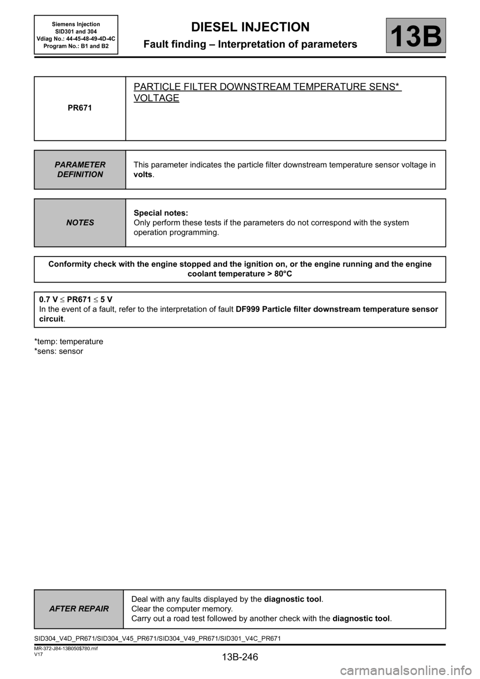
*sens: sensorPR671
PARTICLE FILTER DOWNSTREAM TEMPERATURE SENS*
VOLTAGE
PARAMETER
DEFINITIONThis parameter indicates the particle filter downstream temperature sensor voltage in
volts.
NOTESSpecial notes:
Only perform these tests if the parameters do not correspond with the system
operation programming.
Conformity check with the engine stopped and the ignition on, or the engine running and the engine
coolant temperature > 80°C
0.7 V ≤PR671 ≤5V
In the event of a fault, refer to the interpretation of fault DF999 Particle filter downstream temperature sensor
circuit.
AFTER REPAIRDeal with any faults displayed by the diagnostic tool.
Clear the computer memory.
Carry out a road test followed by another check with the diagnostic tool.
SID304_V4D_PR671/SID304_V45_PR671/SID304_V49_PR671/SID301_V4C_PR671
Page 250 of 329
13B-250
MR-372-J84-13B050$780.mif
V17
DIESEL INJECTION
Fault finding – Interpretation of parameters
Siemens Injection
SID301 and 304
Vdiag No.: 44-45-48-49-4D-4C
Program No.: B1 and B2
13B
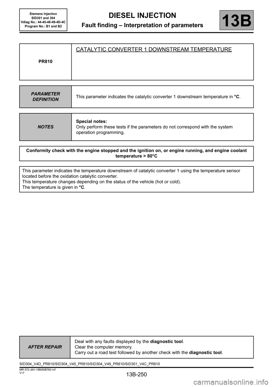
PR810
CATALYTIC CONVERTER 1 DOWNSTREAM TEMPERATURE
PARAMETER
DEFINITIONThis parameter indicates the catalytic converter 1 downstream temperature in °C.
NOTESSpecial notes:
Only perform these tests if the parameters do not correspond with the system
operation programming.
Conformity check with the engine stopped and the ignition on, or engine running, and engine coolant
temperature > 80°C
This parameter indicates the temperature downstream of catalytic converter 1 using the temperature sensor
located before the oxidation catalytic converter.
This temperature changes depending on the status of the vehicle (hot or cold).
The temperature is given in °C.
AFTER REPAIRDeal with any faults displayed by the diagnostic tool.
Clear the computer memory.
Carry out a road test followed by another check with the diagnostic tool.
SID304_V4D_PR810/SID304_V45_PR810/SID304_V49_PR810/SID301_V4C_PR810
Page 251 of 329
13B-251
MR-372-J84-13B050$780.mif
V17
DIESEL INJECTION
Fault finding – Interpretation of parameters
Siemens Injection
SID301 and 304
Vdiag No.: 44-45-48-49-4D-4C
Program No.: B1 and B2
13B
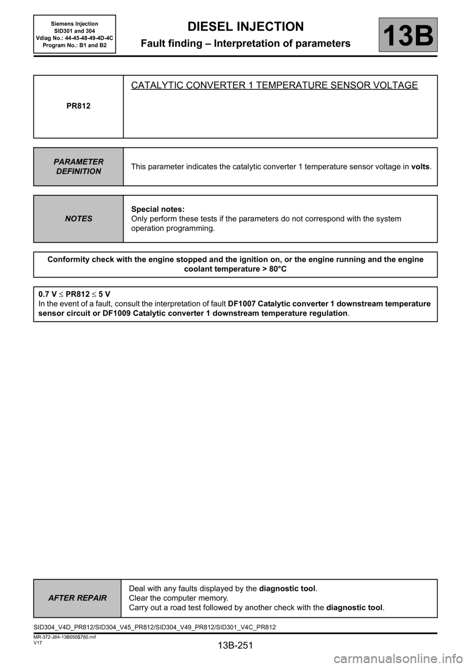
PR812
CATALYTIC CONVERTER 1 TEMPERATURE SENSOR VOLTAGE
PARAMETER
DEFINITIONThis parameter indicates the catalytic converter 1 temperature sensor voltage in volts.
NOTESSpecial notes:
Only perform these tests if the parameters do not correspond with the system
operation programming.
Conformity check with the engine stopped and the ignition on, or the engine running and the engine
coolant temperature > 80°C
0.7 V ≤PR812 ≤5V
In the event of a fault, consult the interpretation of fault DF1007 Catalytic converter 1 downstream temperature
sensor circuit or DF1009 Catalytic converter 1 downstream temperature regulation.
AFTER REPAIRDeal with any faults displayed by the diagnostic tool.
Clear the computer memory.
Carry out a road test followed by another check with the diagnostic tool.
SID304_V4D_PR812/SID304_V45_PR812/SID304_V49_PR812/SID301_V4C_PR812
Page 259 of 329
13B-259
MR-372-J84-13B050$819.mif
V17
DIESEL INJECTION
Fault finding – Interpretation of commands
Siemens Injection
SID301 and 304
Vdiag No.: 44-45-48-49-4D-4C
Program No.: B1 and B2
13B
AC037: Preheating relay.
Activating this lets you listen to the operation of the preheating relay and enables the warning light in the
instrument panel to be illuminated.
AC079: Static actuator test.
Activating this allows you to activate the injection system actuators (simultaneously runs commands
AC003, AC005 to AC008, AC012, AC037, AC213, and AC214).
Run this command with the engine stopped and the engine coolant temperature below 40°C.
AC099: Inhibition of electrical consumers.
AC100: Cancel inhibition of electrical consumers.
AC213: Fuel flow solenoid valve.
AC214: Turbocharger control solenoid valve.
Activating this allows you to listen to the operation of the turbocharger control solenoid valve.
AC233: Thermoplungers no. 1 and no. 2 (Vdiag 45, 49 and 4D only).
AC234: Thermoplunger no. 3 (Vdiag 45, 49 and 4D only).
AC235: Thermoplunger no. 4 (Vdiag 45, 49 and 4D only).
AC236: Coolant pump relay (only for vehicles equipped with a particle filter, except KANGOO II).
AC237: Fuel pump relay (only for vehicles equipped with a particle filter).
Activating this allows you to check the sealing on the 5
th particle filter injector circuit.
AC238: Particle filter injector (Only for vehicles equipped with a particle filter).
AC239: Particle filter temperature sensor fault finding (only for vehicles equipped with a particle filter).
Run this command with the engine stopped and the engine coolant temperature below 40°C.
AC260: Thermoplunger relay.
Activating this allows you to check the three thermoplunger relays.
Page 263 of 329
13B-263
MR-372-J84-13B050$819.mif
V17
DIESEL INJECTION
Fault finding – Interpretation of commands
Siemens Injection
SID301 and 304
Vdiag No.: 44-45-48-49-4D-4C
Program No.: B1 and B2
13B
SC017
CONTINUED
After-Sales regeneration comprises 4 important stages:
– Heating of the engine and checking for a small quantity of soot in the particle filter by measuring the differential
pressure.
– The system changes from combustion mode and starts to regenerate the particle filter. Gradual cooling of the
particle filter.
– End of After-Sales regeneration.
Stopping conditions:
– Dialogue with the diagnostic tool has been lost.
– Vehicle movement detected by speed sensor.
– Brake or clutch pedal depressed.
– Stop regeneration requested by the diagnostic tool.
– End of test.
The procedure lasts 30 minutes.
– At the end of regeneration, a message announces whether the regeneration has been successful or which
operations to carry out.
CONFIRMING THE REGENERATION PROCESS:
At the end of regeneration, a message appears to announce whether the regeneration was successful:
particle filter regeneration successful: regeneration completed correctly.
weight of soot too high - run command SC017 again: regeneration failed because the weight of soot at
the end of regeneration was too high and the temperature upstream of the particle filter was too low. Check
the oil level before starting another regeneration.
weight of soot too high: regeneration failed because the weight of soot at the end of regeneration was
too high in spite of the correct temperature upstream of the particle filter. The particle filter is full of residue
(regeneration impossible), refer to the fault finding chart ALP21 Particle filter warning light lit.
present or stored fault: regeneration failed because faults were declared.
Refer to the interpretation of faults, after resolving the faults, run command SC017 again.
AFTER REPAIRDeal with any faults displayed by the diagnostic tool.
Clear the computer fault memory.
Carry out a road test followed by another check with the diagnostic tool
.
Page 270 of 329
13B-270
MR-372-J84-13B050$819.mif
V17
DIESEL INJECTION
Fault finding – Interpretation of commands
Siemens Injection
SID301 and 304
Vdiag No.: 44-45-48-49-4D-4C
Program No.: B1 and B2
13B
*temp.: temperatureAC239
PARTICLE FILTER TEMPERATURE SENSOR FAULT FINDING
NOTESCarry out this command only under the following conditions:
– DF999 Particle filter downstream temperature sensor circuit,
– DF1000 Particle filter upstream temperature sensor circuit,
With the ignition on and engine switched off and the engine coolant temperature
below 40°C.
This command is used to check the operation of the particle filter temperature sensors.
Use CLIO III, MODUS, MEGANE II ph2, SCENIC II ph2 and KANGOO II Wiring
diagrams Technical Note.
If one of the faults such as DF999 Particle filter downstream temperature sensor circuit or DF1000 Particle
filter upstream temperature sensor circuit is stored, check if it is in short circuit to the + 12 V or in open circuit
using this command.
Procedure:
– Run command AC239 Particle filter temperature sensor fault finding in the presence of the one of these
two faults DF999 Particle filter downstream temperature sensor circuit and/or DF1000 Particle filter
upstream temperature sensor circuit.
– If one or both of these faults becomes present, then the sensor(s) is in short circuit to + 12 V or in open
circuit.
Refer to the interpretation of faults DF999 Particle filter downstream temperature sensor circuit and DF1000
Particle filter upstream temperature sensor circuit.
– If they do not become present, clear the faults on the CLIP diagnostic tool.
SID304_V4D_AC239 / SID304_V45_AC239 / SID304_V49_AC239 / SID301_V4C_AC239
Page 274 of 329
13B-274
MR-372-J84-13B050$897.mif
V17
DIESEL INJECTION
Fault finding – Fault Finding Chart
Siemens Injection
SID301 and 304
Vdiag No.: 44-45-48-49-4D-4C
Program No.: B1 and B2
13B
ALP 2 The engine does not start or starts with difficulty
NOTESOnly address this customer complaint after a complete check with the diagnostic
tool.
Check the presence and conformity of the fuel by running Test 13 Diesel fuel conformity check.
Carry out fault finding on the charge circuit (See Technical Note 6014A, Checking the charging circuit or 87G,
Engine compartment connection unit).
Check the starter and the starter relay (see Technical Note 3632A, Starter fault finding).
Check the injection computer main relay (refer to the interpretation of fault DF015 Main relay control circuit).
Check the injection computer: that the connections and wiring are in good condition, that earths and feeds are
present.
If the wiring is faulty and there is a repair method (see Technical Note 6015A, Repairing electrical wiring,
Wiring: Precautions for repair), repair the wiring, otherwise replace the wiring.
Check the camshaft sensor and TDC sensor, as well as their wiring (refer to the interpretation of faults DF005
Engine speed sensor circuit and DF097 Camshaft sensor circuit).
If there is a repair procedure (see Technical Note 6015A, Repairing electrical wiring, Wiring: Precautions for
repair), repair the wiring, if not replace it.
Check the air inlet circuit (refer to the interpretation of fault DF301 Air inlet circuit).
Check that the damper valve operates correctly (refer to the interpretation of fault DF641 Damper valve circuit).
Check the low pressure fuel supply system by performing test 1 Low pressure supply check and test 2
Internal fuel transfer pump (ITP) check.
Check the high pressure fuel supply system by performing test 3 High pressure fuel pressure solenoid valve
check, test 4 High pressure pump (HPP) and fuel flow solenoid valve check and test 5 Rail high pressure
regulation circuit check.
Check the injectors by performing test 6 Major leak in injectors/injectors open and test 7 Incorrect injection
amount.
AFTER REPAIRCarry out a road test followed by a complete check with the diagnostic tool.
SID301_V44_ALP2 / SID304_V45_ALP2 / SID301_V48_ALP2 / SID304_V49_ALP2 / SID304_V4D_ALP2 / SID301_V4C_ALP2
Page 275 of 329
13B-275
MR-372-J84-13B050$897.mif
V17
DIESEL INJECTION
Fault finding – Fault Finding Chart
Siemens Injection
SID301 and 304
Vdiag No.: 44-45-48-49-4D-4C
Program No.: B1 and B2
13B
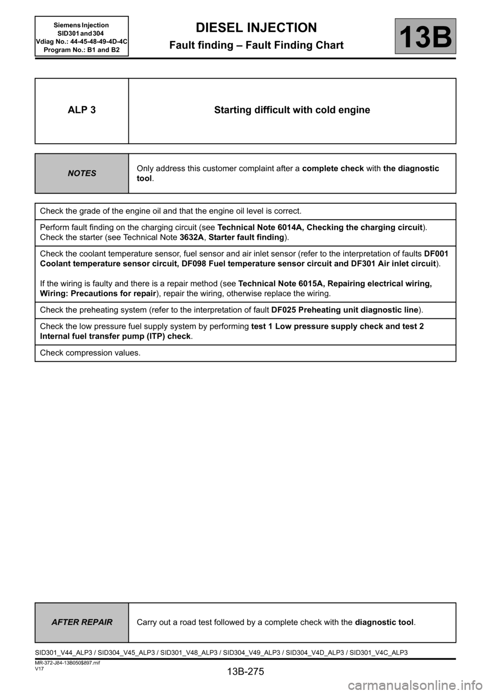
ALP 3 Starting difficult with cold engine
NOTESOnly address this customer complaint after a complete check with the diagnostic
tool.
Check the grade of the engine oil and that the engine oil level is correct.
Perform fault finding on the charging circuit (see Technical Note 6014A, Checking the charging circuit).
Check the starter (see Technical Note 3632A, Starter fault finding).
Check the coolant temperature sensor, fuel sensor and air inlet sensor (refer to the interpretation of faults DF001
Coolant temperature sensor circuit, DF098 Fuel temperature sensor circuit and DF301 Air inlet circuit).
If the wiring is faulty and there is a repair method (see Technical Note 6015A, Repairing electrical wiring,
Wiring: Precautions for repair), repair the wiring, otherwise replace the wiring.
Check the preheating system (refer to the interpretation of fault DF025 Preheating unit diagnostic line).
Check the low pressure fuel supply system by performing test 1 Low pressure supply check and test 2
Internal fuel transfer pump (ITP) check.
Check compression values.
AFTER REPAIRCarry out a road test followed by a complete check with the diagnostic tool.
SID301_V44_ALP3 / SID304_V45_ALP3 / SID301_V48_ALP3 / SID304_V49_ALP3 / SID304_V4D_ALP3 / SID301_V4C_ALP3
Page 277 of 329
13B-277
MR-372-J84-13B050$897.mif
V17
DIESEL INJECTION
Fault finding – Fault Finding Chart
Siemens Injection
SID301 and 304
Vdiag No.: 44-45-48-49-4D-4C
Program No.: B1 and B2
13B
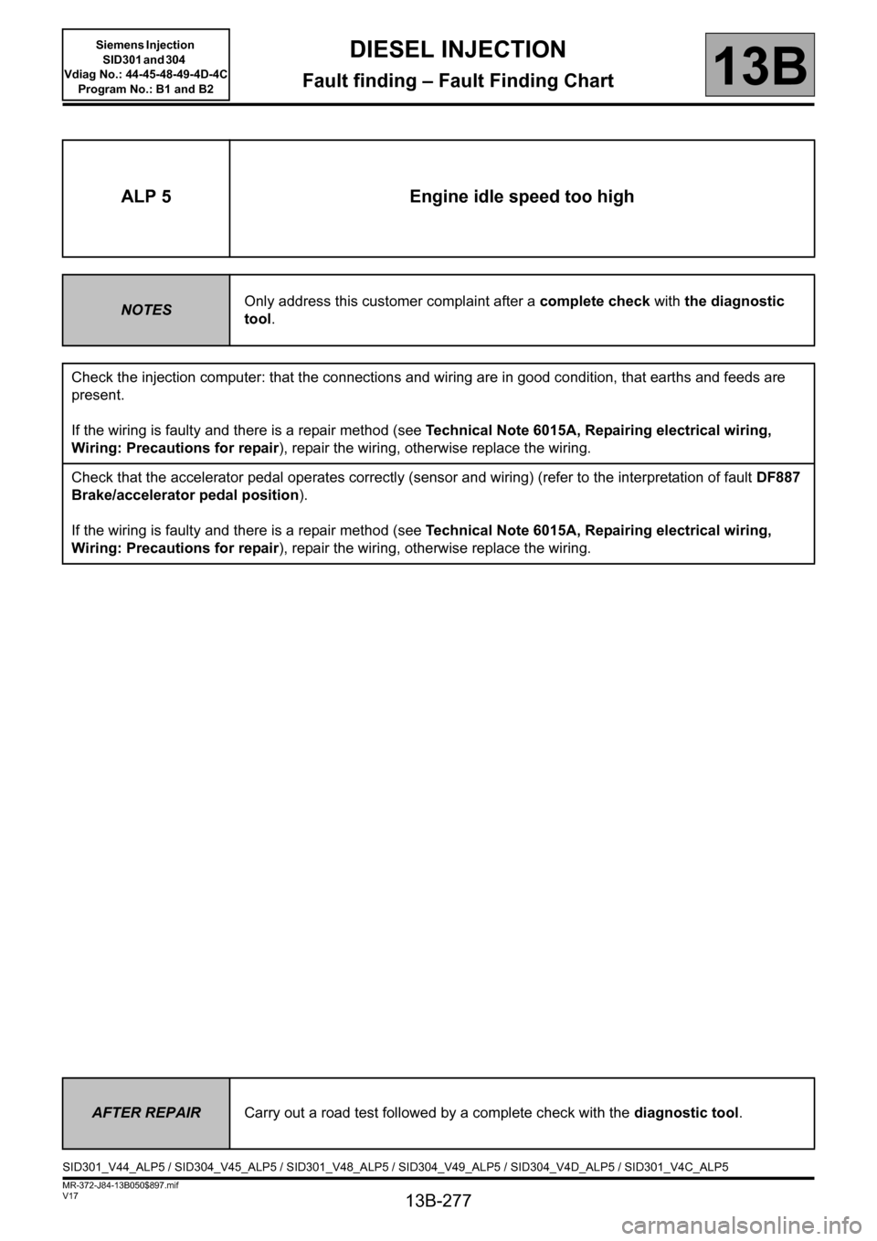
ALP 5 Engine idle speed too high
NOTESOnly address this customer complaint after a complete check with the diagnostic
tool.
Check the injection computer: that the connections and wiring are in good condition, that earths and feeds are
present.
If the wiring is faulty and there is a repair method (see Technical Note 6015A, Repairing electrical wiring,
Wiring: Precautions for repair), repair the wiring, otherwise replace the wiring.
Check that the accelerator pedal operates correctly (sensor and wiring) (refer to the interpretation of fault DF887
Brake/accelerator pedal position).
If the wiring is faulty and there is a repair method (see Technical Note 6015A, Repairing electrical wiring,
Wiring: Precautions for repair), repair the wiring, otherwise replace the wiring.
AFTER REPAIRCarry out a road test followed by a complete check with the diagnostic tool.
SID301_V44_ALP5 / SID304_V45_ALP5 / SID301_V48_ALP5 / SID304_V49_ALP5 / SID304_V4D_ALP5 / SID301_V4C_ALP5