sensor RENAULT SCENIC 2011 J95 / 3.G Engine And Peripherals Siemens Injection Repair Manual
[x] Cancel search | Manufacturer: RENAULT, Model Year: 2011, Model line: SCENIC, Model: RENAULT SCENIC 2011 J95 / 3.GPages: 329, PDF Size: 1.71 MB
Page 161 of 329
13B-161
MR-372-J84-13B050$624.mif
V17
Siemens Injection
SID301 and 304
Vdiag No.: 44-45-48-49-4D-4C
Program No.: B1 and B2DIESEL INJECTION
Fault finding – Interpretation of statuses13B
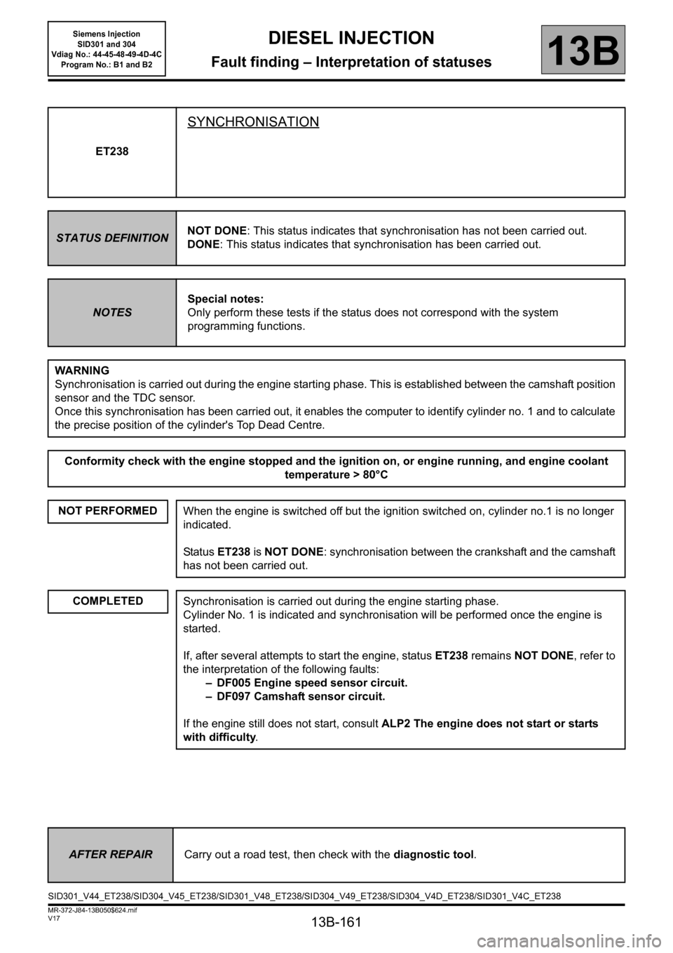
ET238
SYNCHRONISATION
STATUS DEFINITIONNOT DONE: This status indicates that synchronisation has not been carried out.
DONE: This status indicates that synchronisation has been carried out.
NOTESSpecial notes:
Only perform these tests if the status does not correspond with the system
programming functions.
WARNING
Synchronisation is carried out during the engine starting phase. This is established between the camshaft position
sensor and the TDC sensor.
Once this synchronisation has been carried out, it enables the computer to identify cylinder no. 1 and to calculate
the precise position of the cylinder's Top Dead Centre.
Conformity check with the engine stopped and the ignition on, or engine running, and engine coolant
temperature > 80°C
NOT PERFORMED
When the engine is switched off but the ignition switched on, cylinder no.1 is no longer
indicated.
Status ET238 is NOT DONE: synchronisation between the crankshaft and the camshaft
has not been carried out.
COMPLETEDSynchronisation is carried out during the engine starting phase.
Cylinder No. 1 is indicated and synchronisation will be performed once the engine is
started.
If, after several attempts to start the engine, status ET238 remains NOT DONE, refer to
the interpretation of the following faults:
– DF005 Engine speed sensor circuit.
– DF097 Camshaft sensor circuit.
If the engine still does not start, consult ALP2 The engine does not start or starts
with difficulty.
AFTER REPAIRCarry out a road test, then check with the diagnostic tool.
SID301_V44_ET238/SID304_V45_ET238/SID301_V48_ET238/SID304_V49_ET238/SID304_V4D_ET238/SID301_V4C_ET238
Page 162 of 329
13B-162
MR-372-J84-13B050$624.mif
V17
Siemens Injection
SID301 and 304
Vdiag No.: 44-45-48-49-4D-4C
Program No.: B1 and B2DIESEL INJECTION
Fault finding – Interpretation of statuses13B
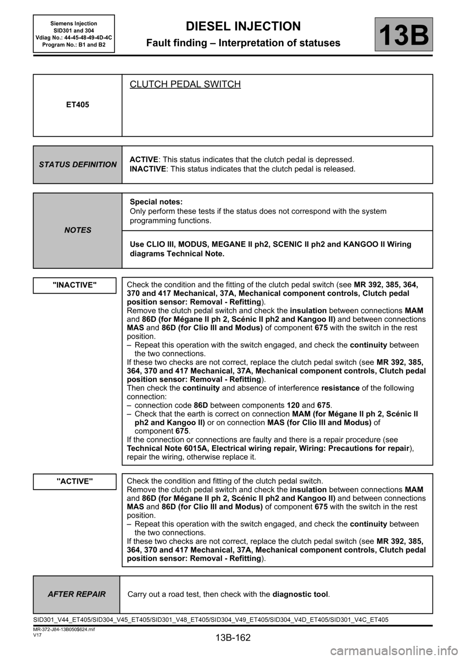
ET405
CLUTCH PEDAL SWITCH
STATUS DEFINITIONACTIVE: This status indicates that the clutch pedal is depressed.
INACTIVE: This status indicates that the clutch pedal is released.
NOTESSpecial notes:
Only perform these tests if the status does not correspond with the system
programming functions.
Use CLIO III, MODUS, MEGANE II ph2, SCENIC II ph2 and KANGOO II Wiring
diagrams Technical Note.
"INACTIVE"
Check the condition and the fitting of the clutch pedal switch (see MR 392, 385, 364,
370 and 417 Mechanical, 37A, Mechanical component controls, Clutch pedal
position sensor: Removal - Refitting).
Remove the clutch pedal switch and check the insulation between connections MAM
and 86D (for Mégane II ph 2, Scénic II ph2 and Kangoo II) and between connections
MAS and 86D (for Clio III and Modus) of component675 with the switch in the rest
position.
– Repeat this operation with the switch engaged, and check the continuity between
the two connections.
If these two checks are not correct, replace the clutch pedal switch (see MR 392, 385,
364, 370 and 417 Mechanical, 37A, Mechanical component controls, Clutch pedal
position sensor: Removal - Refitting).
Then check the continuity and absence of interference resistance of the following
connection:
– connection code 86D between components 120 and 675.
– Check that the earth is correct on connectionMAM (for Mégane II ph 2, Scénic II
ph2 and Kangoo II) or on connectionMAS (for Clio III and Modus) of
component675.
If the connection or connections are faulty and there is a repair procedure (see
Technical Note 6015A, Electrical wiring repair, Wiring: Precautions for repair),
repair the wiring, otherwise replace it.
"ACTIVE"Check the condition and fitting of the clutch pedal switch.
Remove the clutch pedal switch and check the insulation between connections MAM
and 86D (for Mégane II ph 2, Scénic II ph2 and Kangoo II) and between connections
MAS and 86D (for Clio III and Modus) of component675 with the switch in the rest
position.
– Repeat this operation with the switch engaged, and check the continuity between
the two connections.
If these two checks are not correct, replace the clutch pedal switch (see MR 392, 385,
364, 370 and 417 Mechanical, 37A, Mechanical component controls, Clutch pedal
position sensor: Removal - Refitting).
AFTER REPAIRCarry out a road test, then check with the diagnostic tool.
SID301_V44_ET405/SID304_V45_ET405/SID301_V48_ET405/SID304_V49_ET405/SID304_V4D_ET405/SID301_V4C_ET405
Page 176 of 329
13B-176
MR-372-J84-13B050$624.mif
V17
13B
DIESEL INJECTION
Fault finding – Interpretation of statuses
*elec: electric
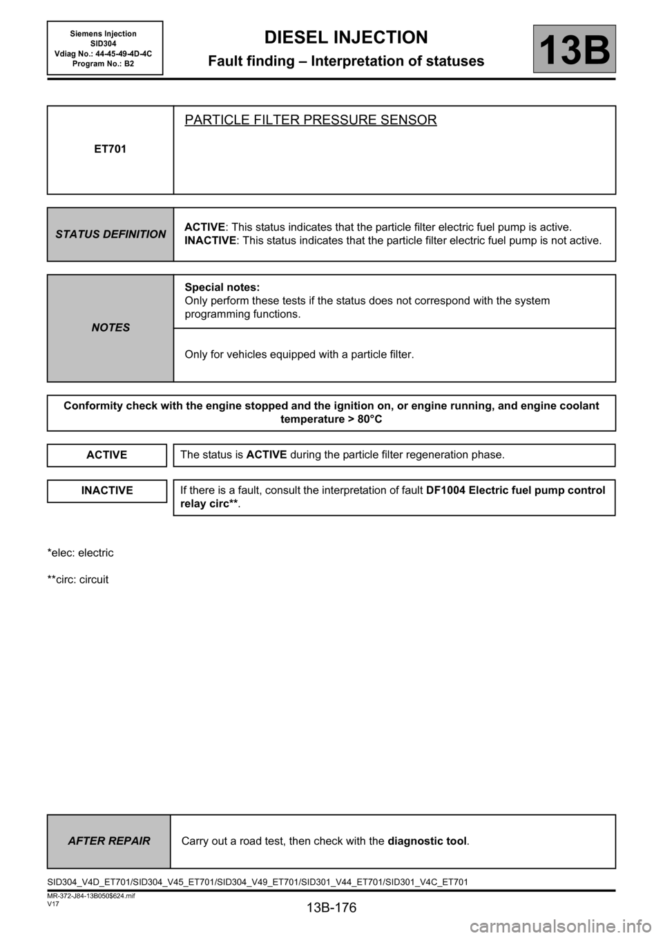
**circ: circuitET701
PARTICLE FILTER PRESSURE SENSOR
STATUS DEFINITIONACTIVE: This status indicates that the particle filter electric fuel pump is active.
INACTIVE: This status indicates that the particle filter electric fuel pump is not active.
NOTESSpecial notes:
Only perform these tests if the status does not correspond with the system
programming functions.
Only for vehicles equipped with a particle filter.
Conformity check with the engine stopped and the ignition on, or engine running, and engine coolant
temperature > 80°C
ACTIVE
INACTIVE
The status is ACTIVE during the particle filter regeneration phase.
If there is a fault, consult the interpretation of fault DF1004 Electric fuel pump control
relay circ**.
AFTER REPAIRCarry out a road test, then check with the diagnostic tool.
SID304_V4D_ET701/SID304_V45_ET701/SID304_V49_ET701/SID301_V44_ET701/SID301_V4C_ET701
Siemens Injection
SID304
Vdiag No.: 44-45-49-4D-4C
Program No.: B2
Page 186 of 329
13B-186
MR-372-J84-13B050$663.mif
V17
13B
DIESEL INJECTION
Fault finding – Parameter summary table
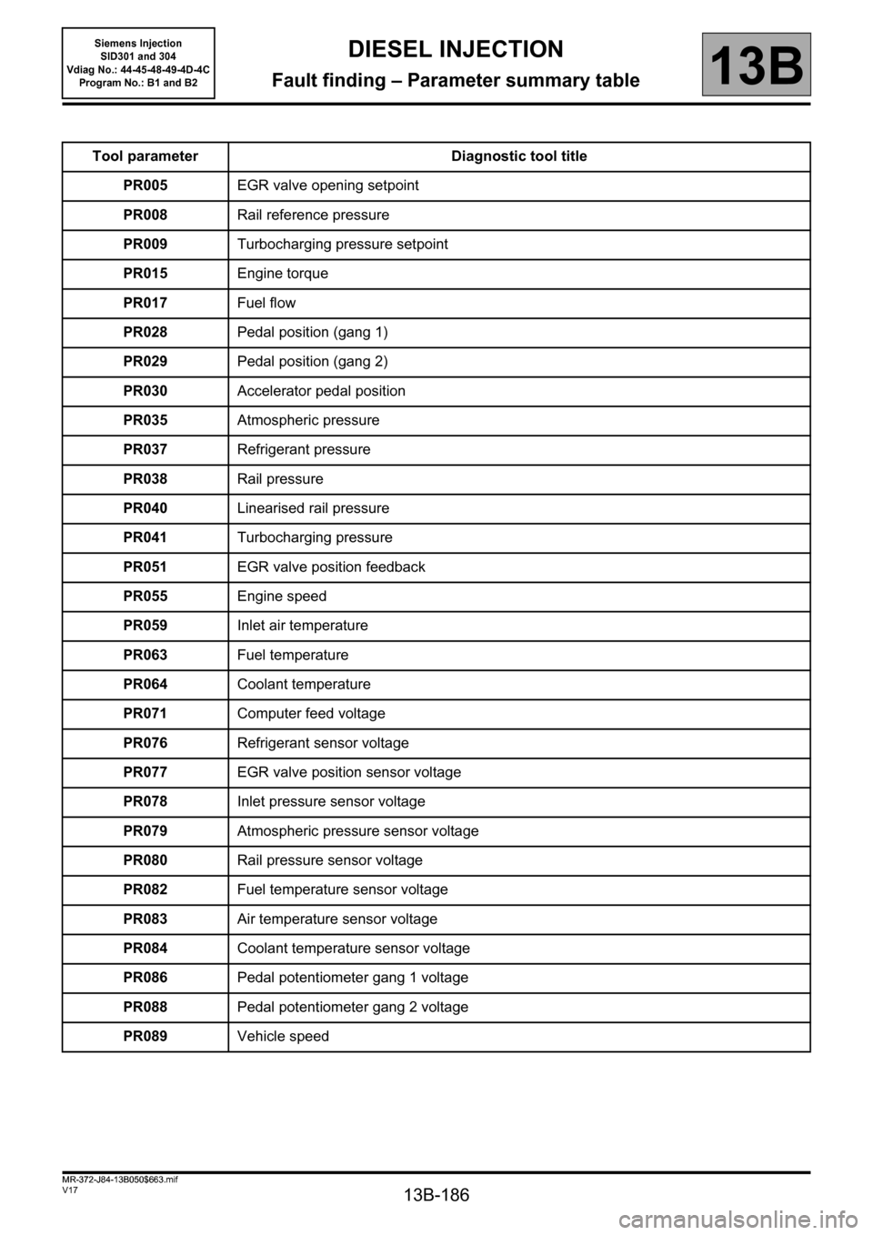
Tool parameter Diagnostic tool title
PR005EGR valve opening setpoint
PR008Rail reference pressure
PR009Turbocharging pressure setpoint
PR015Engine torque
PR017Fuel flow
PR028Pedal position (gang 1)
PR029Pedal position (gang 2)
PR030Accelerator pedal position
PR035Atmospheric pressure
PR037Refrigerant pressure
PR038Rail pressure
PR040Linearised rail pressure
PR041Turbocharging pressure
PR051EGR valve position feedback
PR055Engine speed
PR059Inlet air temperature
PR063Fuel temperature
PR064Coolant temperature
PR071Computer feed voltage
PR076Refrigerant sensor voltage
PR077EGR valve position sensor voltage
PR078Inlet pressure sensor voltage
PR079Atmospheric pressure sensor voltage
PR080Rail pressure sensor voltage
PR082Fuel temperature sensor voltage
PR083Air temperature sensor voltage
PR084Coolant temperature sensor voltage
PR086Pedal potentiometer gang 1 voltage
PR088Pedal potentiometer gang 2 voltage
PR089Vehicle speed
MR-372-J84-13B050$663.mif
Siemens Injection
SID301 and 304
Vdiag No.: 44-45-48-49-4D-4C
Program No.: B1 and B2
Page 187 of 329
13B-187
MR-372-J84-13B050$663.mif
V17
Siemens Injection
SID301 and 304
Vdiag No.: 44-45-48-49-4D-4C
Program No.: B1 and B2DIESEL INJECTION
Fault finding – Parameter summary table13B
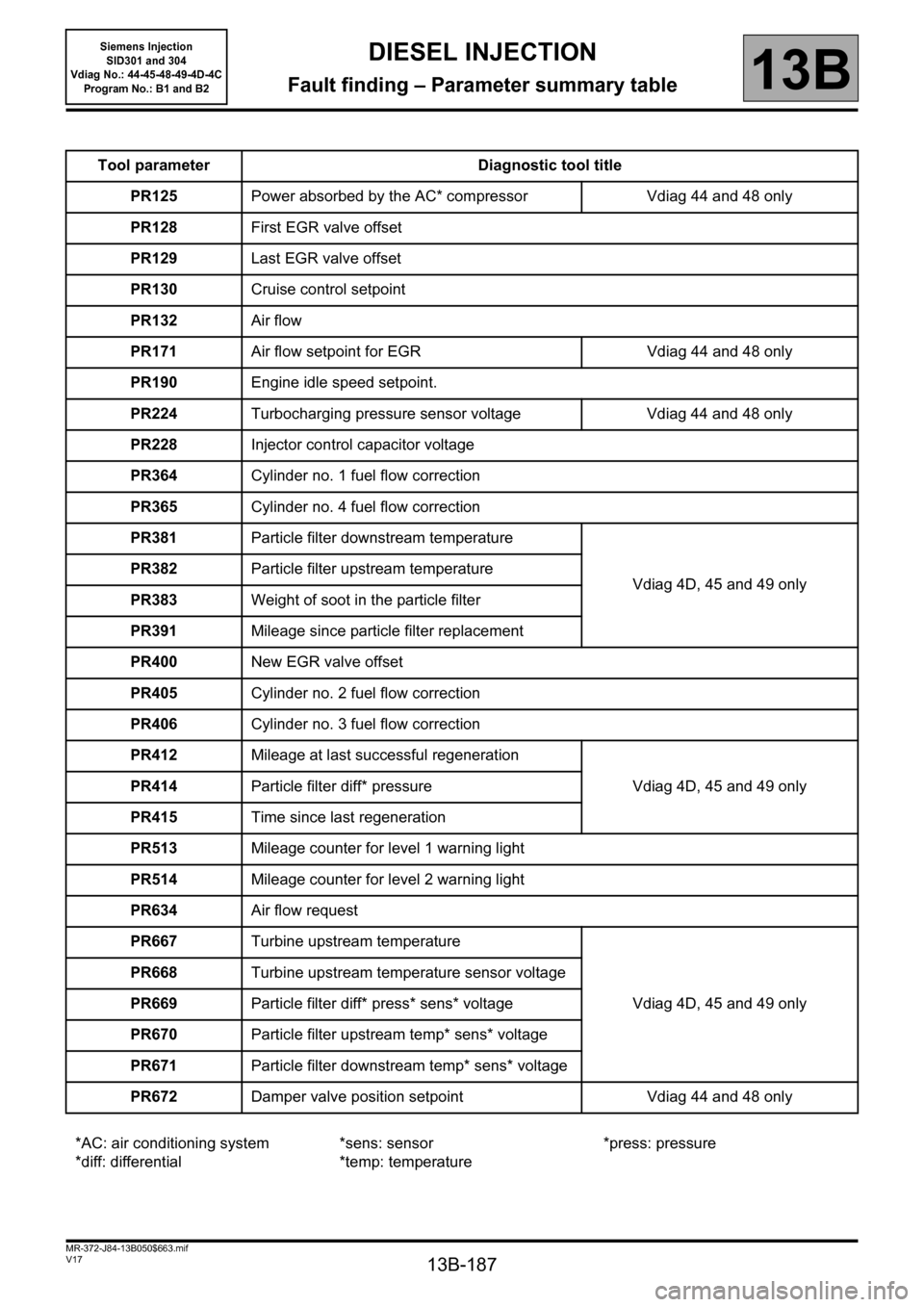
Tool parameter Diagnostic tool title
PR125Power absorbed by the AC* compressor Vdiag 44 and 48 only
PR128First EGR valve offset
PR129Last EGR valve offset
PR130Cruise control setpoint
PR132Air flow
PR171Air flow setpoint for EGR Vdiag 44 and 48 only
PR190Engine idle speed setpoint.
PR224Turbocharging pressure sensor voltage Vdiag 44 and 48 only
PR228Injector control capacitor voltage
PR364Cylinder no. 1 fuel flow correction
PR365Cylinder no. 4 fuel flow correction
PR381Particle filter downstream temperature
Vdiag 4D, 45 and 49 only PR382Particle filter upstream temperature
PR383Weight of soot in the particle filter
PR391Mileage since particle filter replacement
PR400New EGR valve offset
PR405Cylinder no. 2 fuel flow correction
PR406Cylinder no. 3 fuel flow correction
PR412Mileage at last successful regeneration
Vdiag 4D, 45 and 49 only PR414Particle filter diff* pressure
PR415Time since last regeneration
PR513Mileage counter for level 1 warning light
PR514Mileage counter for level 2 warning light
PR634Air flow request
PR667Turbine upstream temperature
Vdiag 4D, 45 and 49 only PR668Turbine upstream temperature sensor voltage
PR669Particle filter diff* press* sens* voltage
PR670Particle filter upstream temp* sens* voltage
PR671Particle filter downstream temp* sens* voltage
PR672Damper valve position setpoint Vdiag 44 and 48 only
*AC: air conditioning system
*diff: differential*sens: sensor
*temp: temperature*press: pressure
Page 188 of 329
13B-188
MR-372-J84-13B050$663.mif
V17
Siemens Injection
SID301 and 304
Vdiag No.: 44-45-48-49-4D-4C
Program No.: B1 and B2DIESEL INJECTION
Fault finding – Parameter summary table13B
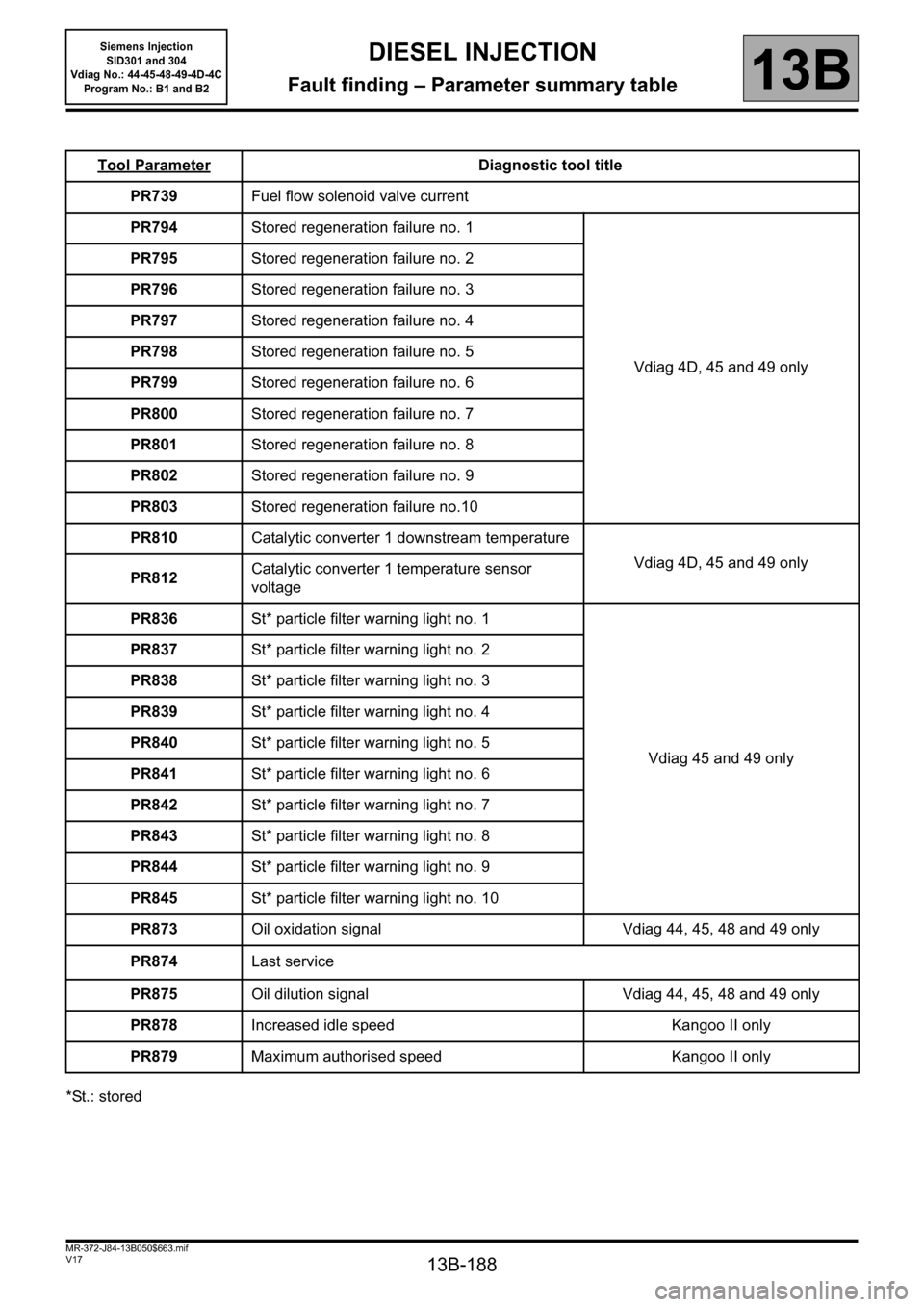
*St.: storedTool Parameter
Diagnostic tool title
PR739Fuel flow solenoid valve current
PR794Stored regeneration failure no. 1
Vdiag 4D, 45 and 49 only PR795Stored regeneration failure no. 2
PR796Stored regeneration failure no. 3
PR797Stored regeneration failure no. 4
PR798Stored regeneration failure no. 5
PR799Stored regeneration failure no. 6
PR800Stored regeneration failure no. 7
PR801Stored regeneration failure no. 8
PR802Stored regeneration failure no. 9
PR803Stored regeneration failure no.10
PR810Catalytic converter 1 downstream temperature
Vdiag 4D, 45 and 49 only
PR812Catalytic converter 1 temperature sensor
voltage
PR836St* particle filter warning light no. 1
Vdiag 45 and 49 only PR837St* particle filter warning light no. 2
PR838St* particle filter warning light no. 3
PR839St* particle filter warning light no. 4
PR840St* particle filter warning light no. 5
PR841St* particle filter warning light no. 6
PR842St* particle filter warning light no. 7
PR843St* particle filter warning light no. 8
PR844St* particle filter warning light no. 9
PR845St* particle filter warning light no. 10
PR873Oil oxidation signal Vdiag 44, 45, 48 and 49 only
PR874Last service
PR875Oil dilution signal Vdiag 44, 45, 48 and 49 only
PR878Increased idle speed Kangoo II only
PR879Maximum authorised speed Kangoo II only
Page 194 of 329
13B-194
MR-372-J84-13B050$702.mif
V17
DIESEL INJECTION
Fault finding – Interpretation of parameters
Siemens Injection
SID301 and 304
Vdiag No.: 44-45-48-49-4D-4C
Program No.: B1 and B2
13B
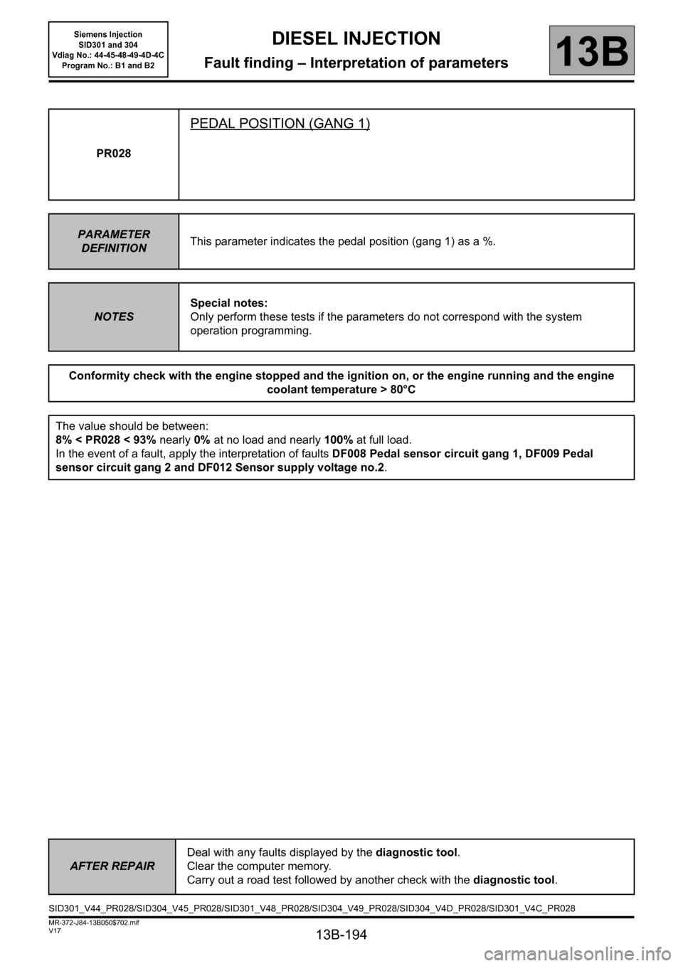
PR028
PEDAL POSITION (GANG 1)
PARAMETER
DEFINITIONThis parameter indicates the pedal position (gang 1) as a %.
NOTESSpecial notes:
Only perform these tests if the parameters do not correspond with the system
operation programming.
Conformity check with the engine stopped and the ignition on, or the engine running and the engine
coolant temperature > 80°C
The value should be between:
8% < PR028 < 93% nearly 0% at no load and nearly 100% at full load.
In the event of a fault, apply the interpretation of faults DF008 Pedal sensor circuit gang 1, DF009 Pedal
sensor circuit gang 2 and DF012 Sensor supply voltage no.2.
AFTER REPAIRDeal with any faults displayed by the diagnostic tool.
Clear the computer memory.
Carry out a road test followed by another check with the diagnostic tool.
SID301_V44_PR028/SID304_V45_PR028/SID301_V48_PR028/SID304_V49_PR028/SID304_V4D_PR028/SID301_V4C_PR028
Page 195 of 329
13B-195
MR-372-J84-13B050$702.mif
V17
DIESEL INJECTION
Fault finding – Interpretation of parameters
Siemens Injection
SID301 and 304
Vdiag No.: 44-45-48-49-4D-4C
Program No.: B1 and B2
13B
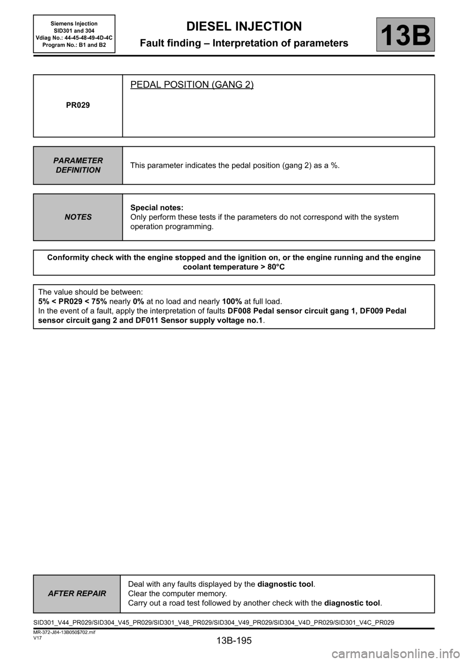
PR029
PEDAL POSITION (GANG 2)
PARAMETER
DEFINITIONThis parameter indicates the pedal position (gang 2) as a %.
NOTESSpecial notes:
Only perform these tests if the parameters do not correspond with the system
operation programming.
Conformity check with the engine stopped and the ignition on, or the engine running and the engine
coolant temperature > 80°C
The value should be between:
5% < PR029 < 75% nearly 0% at no load and nearly 100% at full load.
In the event of a fault, apply the interpretation of faults DF008 Pedal sensor circuit gang 1, DF009 Pedal
sensor circuit gang 2 and DF011 Sensor supply voltage no.1.
AFTER REPAIRDeal with any faults displayed by the diagnostic tool.
Clear the computer memory.
Carry out a road test followed by another check with the diagnostic tool.
SID301_V44_PR029/SID304_V45_PR029/SID301_V48_PR029/SID304_V49_PR029/SID304_V4D_PR029/SID301_V4C_PR029
Page 196 of 329
13B-196
MR-372-J84-13B050$702.mif
V17
DIESEL INJECTION
Fault finding – Interpretation of parameters
Siemens Injection
SID301 and 304
Vdiag No.: 44-45-48-49-4D-4C
Program No.: B1 and B2
13B
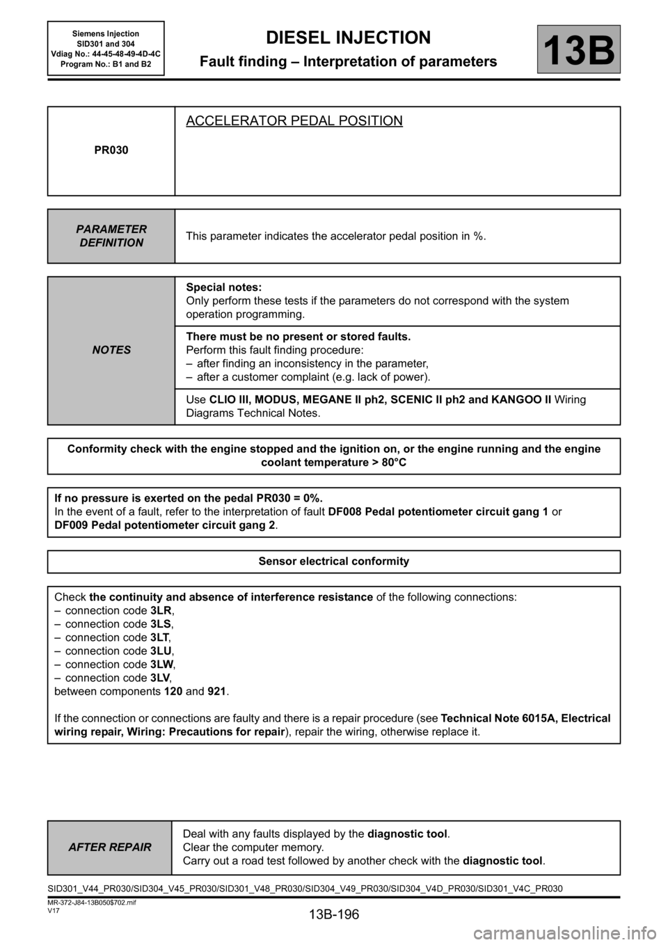
PR030
ACCELERATOR PEDAL POSITION
PARAMETER
DEFINITIONThis parameter indicates the accelerator pedal position in %.
NOTESSpecial notes:
Only perform these tests if the parameters do not correspond with the system
operation programming.
There must be no present or stored faults.
Perform this fault finding procedure:
– after finding an inconsistency in the parameter,
– after a customer complaint (e.g. lack of power).
Use CLIO III, MODUS, MEGANE II ph2, SCENIC II ph2 and KANGOO II Wiring
Diagrams Technical Notes.
Conformity check with the engine stopped and the ignition on, or the engine running and the engine
coolant temperature > 80°C
If no pressure is exerted on the pedal PR030 = 0%.
In the event of a fault, refer to the interpretation of fault DF008 Pedal potentiometer circuit gang 1 or
DF009 Pedal potentiometer circuit gang 2.
Sensor electrical conformity
Check the continuity and absence of interference resistance of the following connections:
– connection code3LR,
– connection code3LS,
– connection code3LT,
– connection code3LU,
– connection code3LW,
– connection code3LV,
between components 120 and 921.
If the connection or connections are faulty and there is a repair procedure (see Technical Note 6015A, Electrical
wiring repair, Wiring: Precautions for repair), repair the wiring, otherwise replace it.
AFTER REPAIRDeal with any faults displayed by the diagnostic tool.
Clear the computer memory.
Carry out a road test followed by another check with the diagnostic tool.
SID301_V44_PR030/SID304_V45_PR030/SID301_V48_PR030/SID304_V49_PR030/SID304_V4D_PR030/SID301_V4C_PR030
Page 197 of 329
13B-197
MR-372-J84-13B050$702.mif
V17
DIESEL INJECTION
Fault finding – Interpretation of parameters
Siemens Injection
SID301 and 304
Vdiag No.: 44-45-48-49-4D-4C
Program No.: B1 and B2
13B
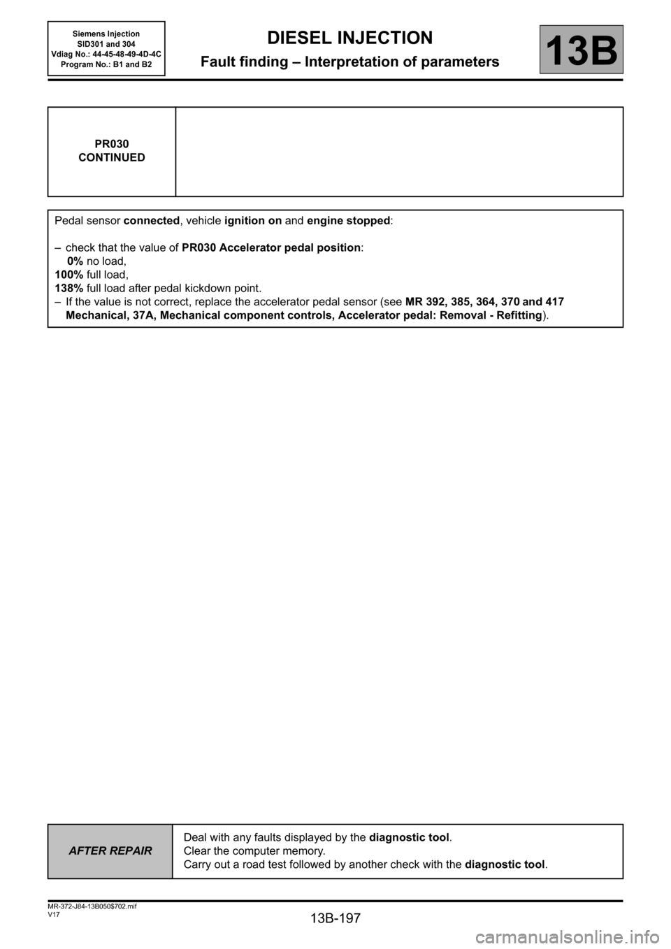
PR030
CONTINUED
Pedal sensor connected, vehicle ignition on and engine stopped:
– check that the value of PR030 Accelerator pedal position:
0% no load,
100% full load,
138% full load after pedal kickdown point.
– If the value is not correct, replace the accelerator pedal sensor (see MR 392, 385, 364, 370
and 417
Mechanical, 37A, Mechanical component controls, Accelerator pedal: Removal - Refitting).
AFTER REPAIRDeal with any faults displayed by the diagnostic tool.
Clear the computer memory.
Carry out a road test followed by another check with the diagnostic tool.