brake sensor RENAULT SCENIC 2011 J95 / 3.G Engine And Peripherals Siemens Injection User Guide
[x] Cancel search | Manufacturer: RENAULT, Model Year: 2011, Model line: SCENIC, Model: RENAULT SCENIC 2011 J95 / 3.GPages: 329, PDF Size: 1.71 MB
Page 282 of 329

13B-282
MR-372-J84-13B050$897.mif
V17
DIESEL INJECTION
Fault finding – Fault Finding Chart
Siemens Injection
SID301 and 304
Vdiag No.: 44-45-48-49-4D-4C
Program No.: B1 and B2
13B
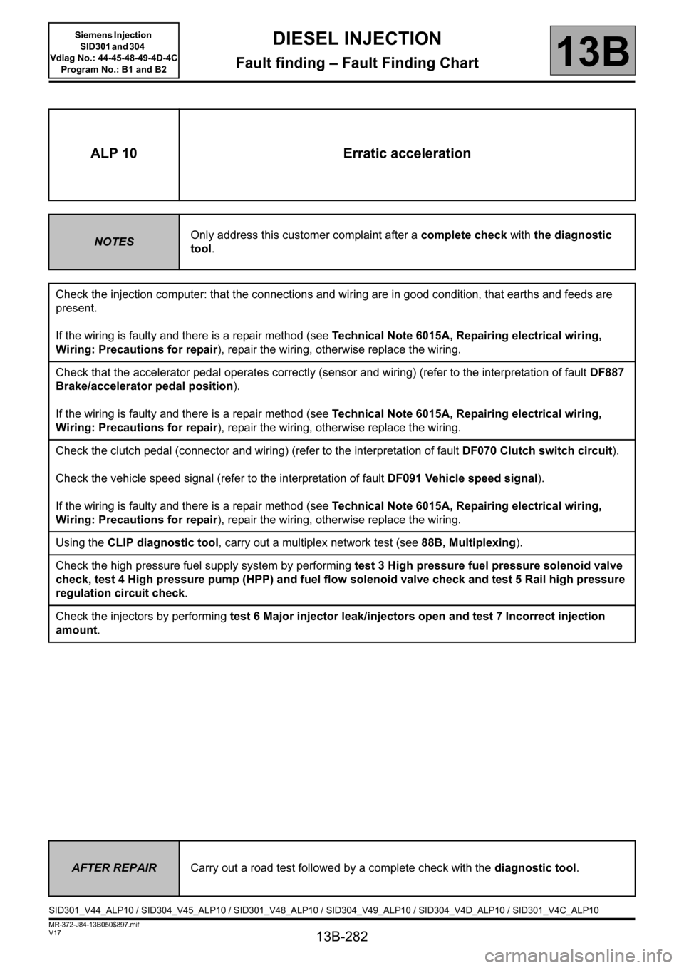
ALP 10 Erratic acceleration
NOTESOnly address this customer complaint after a complete check with the diagnostic
tool.
Check the injection computer: that the connections and wiring are in good condition, that earths and feeds are
present.
If the wiring is faulty and there is a repair method (see Technical Note 6015A, Repairing electrical wiring,
Wiring: Precautions for repair), repair the wiring, otherwise replace the wiring.
Check that the accelerator pedal operates correctly (sensor and wiring) (refer to the interpretation of fault DF887
Brake/accelerator pedal position).
If the wiring is faulty and there is a repair method (see Technical Note 6015A, Repairing electrical wiring,
Wiring: Precautions for repair), repair the wiring, otherwise replace the wiring.
Check the clutch pedal (connector and wiring) (refer to the interpretation of fault DF070 Clutch switch circuit).
Check the vehicle speed signal (refer to the interpretation of fault DF091 Vehicle speed signal).
If the wiring is faulty and there is a repair method (see Technical Note 6015A, Repairing electrical wiring,
Wiring: Precautions for repair), repair the wiring, otherwise replace the wiring.
Using the CLIP diagnostic tool, carry out a multiplex network test (see 88B, Multiplexing).
Check the high pressure fuel supply system by performing test 3 High pressure fuel pressure solenoid valve
check, test 4 High pressure pump (HPP) and fuel flow solenoid valve check and test 5 Rail high pressure
regulation circuit check.
Check the injectors by performing test 6 Major injector leak/injectors open and test 7 Incorrect injection
amount.
AFTER REPAIRCarry out a road test followed by a complete check with the diagnostic tool.
SID301_V44_ALP10 / SID304_V45_ALP10 / SID301_V48_ALP10 / SID304_V49_ALP10 / SID304_V4D_ALP10 / SID301_V4C_ALP10
Page 283 of 329

13B-283
MR-372-J84-13B050$897.mif
V17
DIESEL INJECTION
Fault finding – Fault Finding Chart
Siemens Injection
SID301 and 304
Vdiag No.: 44-45-48-49-4D-4C
Program No.: B1 and B2
13B
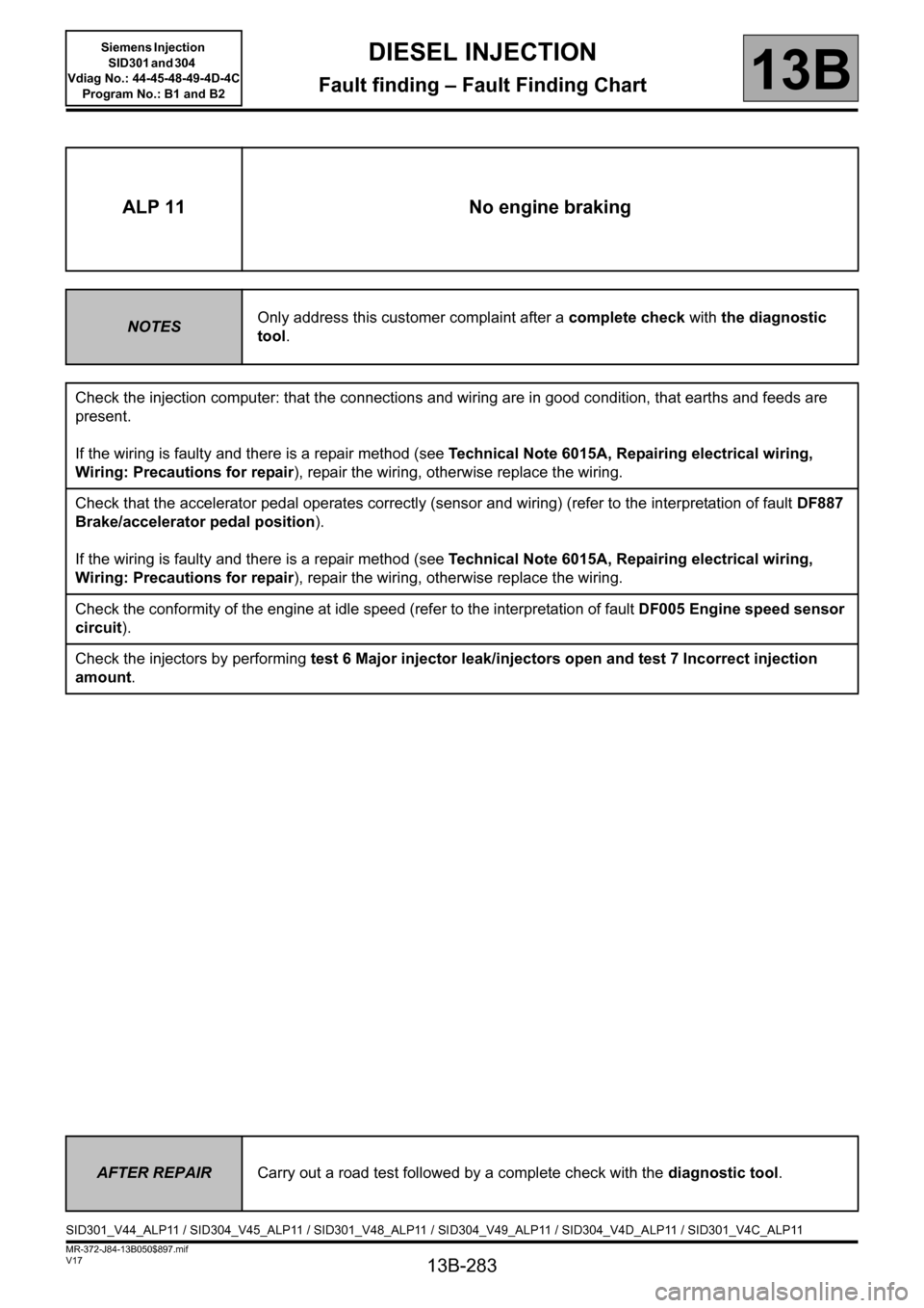
ALP 11 No engine braking
NOTESOnly address this customer complaint after a complete check with the diagnostic
tool.
Check the injection computer: that the connections and wiring are in good condition, that earths and feeds are
present.
If the wiring is faulty and there is a repair method (see Technical Note 6015A, Repairing electrical wiring,
Wiring: Precautions for repair), repair the wiring, otherwise replace the wiring.
Check that the accelerator pedal operates correctly (sensor and wiring) (refer to the interpretation of fault DF887
Brake/accelerator pedal position).
If the wiring is faulty and there is a repair method (see Technical Note 6015A, Repairing electrical wiring,
Wiring: Precautions for repair), repair the wiring, otherwise replace the wiring.
Check the conformity of the engine at idle speed (refer to the interpretation of fault DF005 Engine speed sensor
circuit).
Check the injectors by performing test 6 Major injector leak/injectors open and test 7 Incorrect injection
amount.
AFTER REPAIRCarry out a road test followed by a complete check with the diagnostic tool.
SID301_V44_ALP11 / SID304_V45_ALP11 / SID301_V48_ALP11 / SID304_V49_ALP11 / SID304_V4D_ALP11 / SID301_V4C_ALP11
Page 284 of 329

13B-284
MR-372-J84-13B050$897.mif
V17
DIESEL INJECTION
Fault finding – Fault Finding Chart
Siemens Injection
SID301 and 304
Vdiag No.: 44-45-48-49-4D-4C
Program No.: B1 and B2
13B
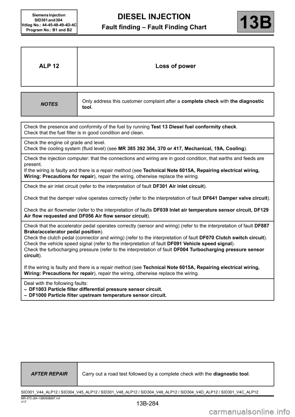
ALP 12 Loss of power
NOTESOnly address this customer complaint after a complete check with the diagnostic
tool.
Check the presence and conformity of the fuel by running Test 13 Diesel fuel conformity check.
Check that the fuel filter is in good condition and clean.
Check the engine oil grade and level.
Check the cooling system (fluid level) (see MR 385 392 364, 370 or 417, Mechanical, 19A, Cooling).
Check the injection computer: that the connections and wiring are in good condition, that earths and feeds are
present.
If the wiring is faulty and there is a repair method (see Technical Note 6015A, Repairing electrical wiring,
Wiring: Precautions for repair), repair the wiring, otherwise replace the wiring.
Check the air inlet circuit (refer to the interpretation of fault DF301 Air inlet circuit).
Check that the damper valve operates correctly (refer to the interpretation of fault DF641 Damper valve circuit).
Check the air flowmeter (refer to the interpretation of faults DF039 Inlet air temperature sensor circuit, DF129
Air flow requested and DF056 Air flow sensor circuit).
Check that the accelerator pedal operates correctly (sensor and wiring) (refer to the interpretation of fault DF887
Brake/accelerator pedal position).
Check the clutch pedal (connector and wiring) (refer to the interpretation of fault DF070 Clutch switch circuit).
Check the vehicle speed signal (refer to the interpretation of fault DF091 Vehicle speed signal).
Check the turbocharging pressure (refer to the interpretation of fault DF004 Turbocharging pressure sensor
circuit).
If the wiring is faulty and there is a repair method (see Technical Note 6015A, Repairing electrical wiring,
Wiring: Precautions for repair), repair the wiring, otherwise replace the wiring.
Deal with the following faults:
– DF1003 Particle filter differential pressure sensor circuit.
– DF1000 Particle filter upstream temperature sensor circuit.
AFTER REPAIRCarry out a road test followed by a complete check with the diagnostic tool.
SID301_V44_ALP12 / SID304_V45_ALP12 / SID301_V48_ALP12 / SID304_V49_ALP12 / SID304_V4D_ALP12 / SID301_V4C_ALP12