fuel filter RENAULT SCENIC 2011 J95 / 3.G Engine And Peripherals Siemens Injection User Guide
[x] Cancel search | Manufacturer: RENAULT, Model Year: 2011, Model line: SCENIC, Model: RENAULT SCENIC 2011 J95 / 3.GPages: 329, PDF Size: 1.71 MB
Page 30 of 329
13B-30
MR-372-J84-13B050$312.mif
V17
13B
DIESEL INJECTION
Fault finding – Configurations and programming
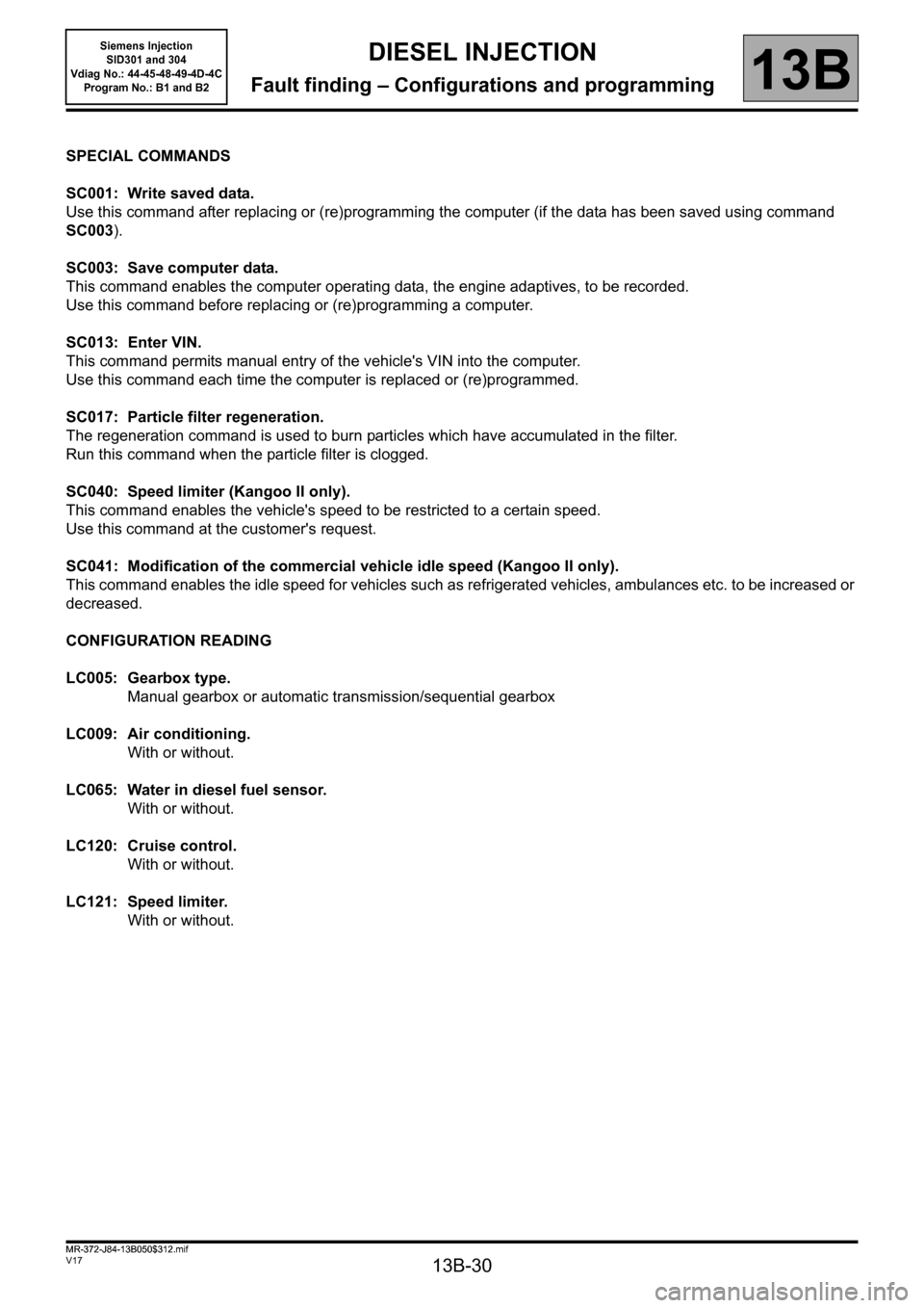
SPECIAL COMMANDS
SC001: Write saved data.
Use this command after replacing or (re)programming the computer (if the data has been saved using command
SC003).
SC003: Save computer data.
This command enables the computer operating data, the engine adaptives, to be recorded.
Use this command before replacing or (re)programming a computer.
SC013: Enter VIN.
This command permits manual entry of the vehicle's VIN into the computer.
Use this command each time the computer is replaced or (re)programmed.
SC017: Particle filter regeneration.
The regeneration command is used to burn particles which have accumulated in the filter.
Run this command when the particle filter is clogged.
SC040: Speed limiter (Kangoo II only).
This command enables the vehicle's speed to be restricted to a certain speed.
Use this command at the customer's request.
SC041: Modification of the commercial vehicle idle speed (Kangoo II only).
This command enables the idle speed for vehicles such as refrigerated vehicles, ambulances etc. to be increased or
decreased.
CONFIGURATION READING
LC005: Gearbox type.
Manual gearbox or automatic transmission/sequential gearbox
LC009: Air conditioning.
With or without.
LC065: Water in diesel fuel sensor.
With or without.
LC120: Cruise control.
With or without.
LC121: Speed limiter.
With or without.
MR-372-J84-13B050$312.mif
Siemens Injection
SID301 and 304
Vdiag No.: 44-45-48-49-4D-4C
Program No.: B1 and B2
Page 34 of 329
13B-34
MR-372-J84-13B050$351.mif
V17
Siemens Injection
SID301 and 304
Vdiag No.: 44-45-48-49-4D-4C
Program No.: B1 and B2DIESEL INJECTION
Fault finding – Fault summary table13B
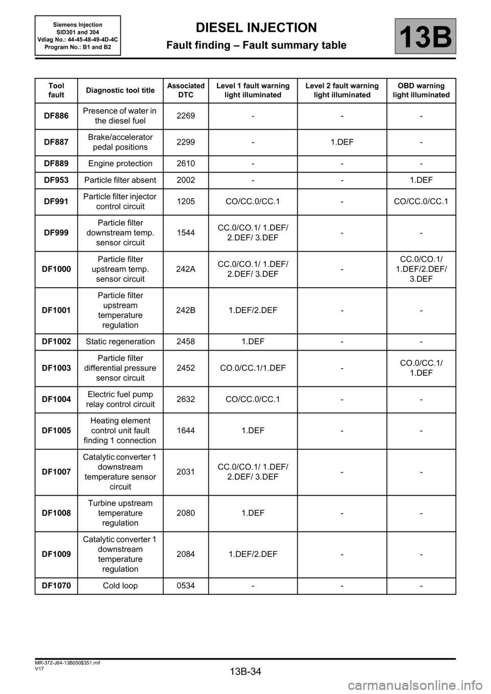
Tool
faultDiagnostic tool titleAssociated
DTCLevel 1 fault warning
light illuminatedLevel 2 fault warning
light illuminatedOBD warning
light illuminated
DF886Presence of water in
the diesel fuel2269 - - -
DF887Brake/accelerator
pedal positions2299 - 1.DEF -
DF889Engine protection 2610 - - -
DF953Particle filter absent 2002 - - 1.DEF
DF991Particle filter injector
control circuit 1205 CO/CC.0/CC.1 - CO/CC.0/CC.1
DF999Particle filter
downstream temp.
sensor circuit1544CC.0/CO.1/ 1.DEF/
2.DEF/ 3.DEF--
DF1000Particle filter
upstream temp.
sensor circuit242ACC.0/CO.1/ 1.DEF/
2.DEF/ 3.DEF-CC.0/CO.1/
1.DEF/2.DEF/
3.DEF
DF1001Particle filter
upstream
temperature
regulation 242B 1.DEF/2.DEF - -
DF1002Static regeneration 2458 1.DEF - -
DF1003Particle filter
differential pressure
sensor circuit 2452 CO.0/CC.1/1.DEF -CO.0/CC.1/
1.DEF
DF1004Electric fuel pump
relay control circuit 2632 CO/CC.0/CC.1 - -
DF1005Heating element
control unit fault
finding 1 connection 1644 1.DEF - -
DF1007Catalytic converter 1
downstream
temperature sensor
circuit 2031CC.0/CO.1/ 1.DEF/
2.DEF/ 3.DEF--
DF1008Turbine upstream
temperature
regulation 2080 1.DEF - -
DF1009Catalytic converter 1
downstream
temperature
regulation 2084 1.DEF/2.DEF - -
DF1070Cold loop 0534 - - -
Page 72 of 329
13B-72
MR-372-J84-13B050$429.mif
V17
DIESEL INJECTION
Fault finding – Interpretation of faults
Siemens Injection
SID301 and 304
Vdiag No.: 44-45-48-49-4D-4C
Program No.: B1 and B2
13B
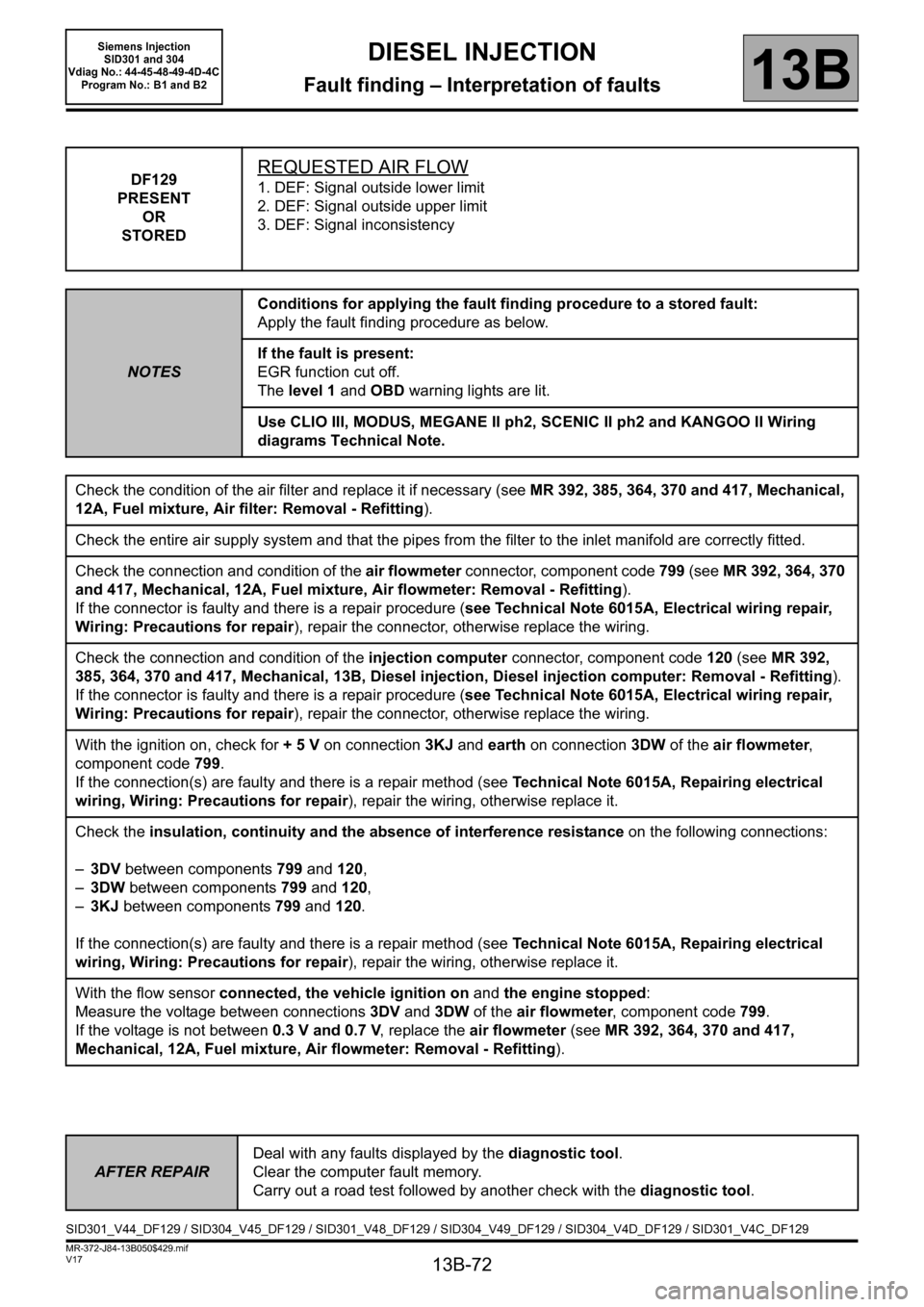
DF129
PRESENT
OR
STOREDREQUESTED AIR FLOW
1. DEF: Signal outside lower limit
2. DEF: Signal outside upper limit
3. DEF: Signal inconsistency
NOTESConditions for applying the fault finding procedure to a stored fault:
Apply the fault finding procedure as below.
If the fault is present:
EGR function cut off.
The level 1 and OBD warning lights are lit.
Use CLIO III, MODUS, MEGANE II ph2, SCENIC II ph2 and KANGOO II Wiring
diagrams Technical Note.
Check the condition of the air filter and replace it if necessary (see MR 392, 385, 364, 370 and 417, Mechanical,
12A, Fuel mixture, Air filter: Removal - Refitting).
Check the entire air supply system and that the pipes from the filter to the inlet manifold are correctly fitted.
Check the connection and condition of the air flowmeter connector, component code 799 (see MR 392, 364, 370
and 417, Mechanical, 12A, Fuel mixture, Air flowmeter: Removal - Refitting).
If the connector is faulty and there is a repair procedure (see Technical Note 6015A, Electrical wiring repair,
Wiring: Precautions for repair), repair the connector, otherwise replace the wiring.
Check the connection and condition of the injection computer connector, component code 120 (see MR 392,
385, 364, 370 and 417, Mechanical, 13B, Diesel injection, Diesel injection computer: Removal - Refitting).
If the connector is faulty and there is a repair procedure (see Technical Note 6015A, Electrical wiring repair,
Wiring: Precautions for repair), repair the connector, otherwise replace the wiring.
With the ignition on, check for + 5 V on connection 3KJ and earth on connection 3DW of the air flowmeter,
component code 799.
If the connection(s) are faulty and there is a repair method (see Technical Note 6015A, Repairing electrical
wiring, Wiring: Precautions for repair), repair the wiring, otherwise replace it.
Check the insulation, continuity and the absence of interference resistance on the following connections:
–3DV between components 799 and 120,
–3DW between components 799 and 120,
–3KJ between components 799 and 120.
If the connection(s) are faulty and there is a repair method (see Technical Note 6015A, Repairing electrical
wiring, Wiring: Precautions for repair), repair the wiring, otherwise replace it.
With the flow sensor connected, the vehicle ignition on and the engine stopped:
Measure the voltage between connections 3DV and 3DW of the air flowmeter, component code 799.
If the voltage is not between 0.3 V and 0.7 V, replace the air flowmeter (see MR 392, 364, 370 and 417,
Mechanical, 12A, Fuel mixture, Air flowmeter: Removal - Refitting).
AFTER REPAIRDeal with any faults displayed by the diagnostic tool.
Clear the computer fault memory.
Carry out a road test followed by another check with the diagnostic tool.
SID301_V44_DF129 / SID304_V45_DF129 / SID301_V48_DF129 / SID304_V49_DF129 / SID304_V4D_DF129 / SID301_V4C_DF129
Page 85 of 329
13B-85
MR-372-J84-13B050$429.mif
V17
DIESEL INJECTION
Fault finding – Interpretation of faults
Siemens Injection
SID301 and 304
Vdiag No.: 44-45-48-49-4D-4C
Program No.: B1 and B2
13B
*diff: differential
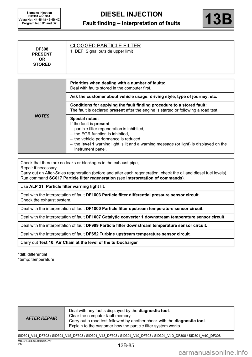
*temp: temperatureDF308
PRESENT
OR
STORED
CLOGGED PARTICLE FILTER
1. DEF: Signal outside upper limit
NOTESPriorities when dealing with a number of faults:
Deal with faults stored in the computer first.
Ask the customer about vehicle usage: driving style, type of journey, etc.
Conditions for applying the fault finding procedure to a stored fault:
The fault is declared present after the engine is started or following a road test.
Special notes:
If the fault is present:
– particle filter regeneration is inhibited,
– the EGR function is inhibited,
– the vehicle performance is reduced,
– the level 1 warning light is lit and a warning message (or light) is displayed on the
instrument panel.
Check that there are no leaks or blockages in the exhaust pipe,
Repair if necessary.
Carry out an After-Sales regeneration (before and after each regeneration, check the oil and diesel fuel levels).
Run command SC017 Particle filter regeneration (see Interpretation of commands).
Use ALP 21: Particle filter warning light lit.
Deal with the interpretation of fault DF1003 Particle filter differential pressure sensor circuit.
Check the exhaust system.
Deal with the interpretation of fault DF1000 Particle filter upstream temperature sensor circuit.
Deal with the interpretation of fault DF1007 Catalytic converter 1 downstream temperature sensor circuit.
Deal with the interpretation of fault DF999 Particle filter downstream temperature sensor circuit.
Deal with the interpretation of fault DF652 Turbine upstream temperature sensor circuit.
Carry out Te s t 1 0: Air Chain at the level of the turbocharger.
AFTER REPAIRDeal with any faults displayed by the diagnostic tool.
Clear the computer fault memory.
Carry out a road test followed by another check with the diagnostic tool.
Explain to the customer how the particle filter system works.
SID301_V44_DF308 / SID304_V45_DF308 / SID301_V48_DF308 / SID304_V49_DF308 / SID304_V4D_DF308 / SID301_V4C_DF308
Page 101 of 329
13B-101
MR-372-J84-13B050$468.mif
V17
DIESEL INJECTION
Fault finding – Interpretation of faults
Siemens Injection
SID301 and 304
Vdiag No.: 44-45-48-49-4D-4C
Program No.: B1 and B2
13B
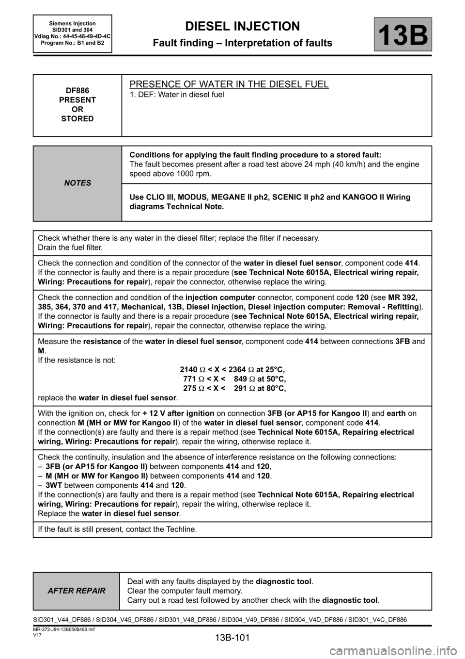
DF886
PRESENT
OR
STOREDPRESENCE OF WATER IN THE DIESEL FUEL
1. DEF: Water in diesel fuel
NOTESConditions for applying the fault finding procedure to a stored fault:
The fault becomes present after a road test above 24 mph (40 km/h) and the engine
speed above 1000 rpm.
Use CLIO III, MODUS, MEGANE II ph2, SCENIC II ph2 and KANGOO II Wiring
diagrams Technical Note.
Check whether there is any water in the diesel filter; replace the filter if necessary.
Drain the fuel filter.
Check the connection and condition of the connector of the water in diesel fuel sensor, component code 414.
If the connector is faulty and there is a repair procedure (see Technical Note 6015A, Electrical wiring repair,
Wiring: Precautions for repair), repair the connector, otherwise replace the wiring.
Check the connection and condition of the injection computer connector, component code 120 (see MR 392,
385, 364, 370 and 417, Mechanical, 13B, Diesel injection, Diesel injection computer: Removal - Refitting).
If the connector is faulty and there is a repair procedure (see Technical Note 6015A, Electrical wiring repair,
Wiring: Precautions for repair), repair the connector, otherwise replace the wiring.
Measure the resistance of the water in diesel fuel sensor, component code 414 between connections 3FB and
M.
If the resistance is not:
2140Ω
With the ignition on, check for + 12 V after ignition on connection 3FB (or AP15 for Kangoo II) and earth on
connection M (MH or MW for Kangoo II) of the water in diesel fuel sensor, component code 414.
If the connection(s) are faulty and there is a repair method (see Technical Note 6015A, Repairing electrical
wiring, Wiring: Precautions for repair), repair the wiring, otherwise replace it.
Check the continuity, insulation and the absence of interference resistance on the following connections:
–3FB (or AP15 for Kangoo II) between components 414 and 120,
–M (MH or MW for Kangoo II) between components 414 and 120,
–3WT between components
414 and 120.
If the connection(s) are faulty and there is a repair method (see Technical Note 6015A, Repairing electrical
wiring, Wiring: Precautions for repair), repair the wiring, otherwise replace it.
Replace the water in diesel fuel sensor.
If the fault is still present, contact the Techline.
AFTER REPAIRDeal with any faults displayed by the diagnostic tool.
Clear the computer fault memory.
Carry out a road test followed by another check with the diagnostic tool.
SID301_V44_DF886 / SID304_V45_DF886 / SID301_V48_DF886 / SID304_V49_DF886 / SID304_V4D_DF886 / SID301_V4C_DF886
Page 111 of 329
13B-111
MR-372-J84-13B050$468.mif
V17
DIESEL INJECTION
Fault finding – Interpretation of faults
Siemens Injection
SID301 and 304
Vdiag No.: 44-45-48-49-4D-4C
Program No.: B1 and B2
13B
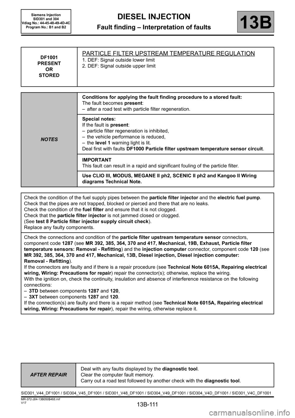
DF1001
PRESENT
OR
STOREDPARTICLE FILTER UPSTREAM TEMPERATURE REGULATION
1. DEF: Signal outside lower limit
2. DEF: Signal outside upper limit
NOTESConditions for applying the fault finding procedure to a stored fault:
The fault becomes present:
– after a road test with particle filter regeneration.
Special notes:
If the fault is present:
– particle filter regeneration is inhibited,
– the vehicle performance is reduced,
–the level 1 warning light is lit.
Deal first with faults DF1000 Particle filter upstream temperature sensor circuit.
IMPORTANT
This fault can result in a rapid and significant fouling of the particle filter.
Use CLIO III, MODUS, MEGANE II ph2, SCENIC II ph2 and Kangoo II Wiring
diagrams Technical Note.
Check the condition of the fuel supply pipes between the particle filter injector and the electric fuel pump.
Check that the pipes are not trapped, blocked or pierced and there that are no leaks.
Check the condition of the fuel filter and ensure that it is not clogged.
Check that the particle filter injector is not jammed closed or clogged.
(See test 8 Particle filter injector supply circuit check).
Replace any faulty components.
Check the connections and condition of the particle filter upstream temperature sensor connectors,
component code 1287 (see MR 392, 385, 364, 370 and 417, Mechanical, 19B, Exhaust, Particle filter
temperature sensors: Removal - Refitting) and the injection computer connector, component code 120 (see
MR 392, 385, 364, 370 and 417, Mechanical, 13B, Diesel injection, Diesel injection computer:
Removal - Refitting).
If the connectors are faulty and if there is a repair procedure (see Technical Note 6015A, Repairing electrical
wiring, Wiring: Precautions for repair) repair the connector(s); otherwise, replace the wiring.
With the ignition on, check the continuity, insulation and absence of interference resistance on the following
connections:
–3TD between components 1287 and 120,
–3XT between components 1287 and 120.
If the connection(s) are faulty and there is a repair method (see Technical Note 6015A, Repairing electrical
wiring, Wiring: Precautions for repair), repair the wiring, otherwise replace it.
AFTER REPAIRDeal with any faults displayed by the diagnostic tool.
Clear the computer fault memory.
Carry out a road test followed by another check with the diagnostic tool.
SID301_V44_DF1001 / SID304_V45_DF1001 / SID301_V48_DF1001 / SID304_V49_DF1001 / SID304_V4D_DF1001 / SID301_V4C_DF1001
Page 112 of 329
13B-112
MR-372-J84-13B050$468.mif
V17
DIESEL INJECTION
Fault finding – Interpretation of faults
Siemens Injection
SID301 and 304
Vdiag No.: 44-45-48-49-4D-4C
Program No.: B1 and B2
13B
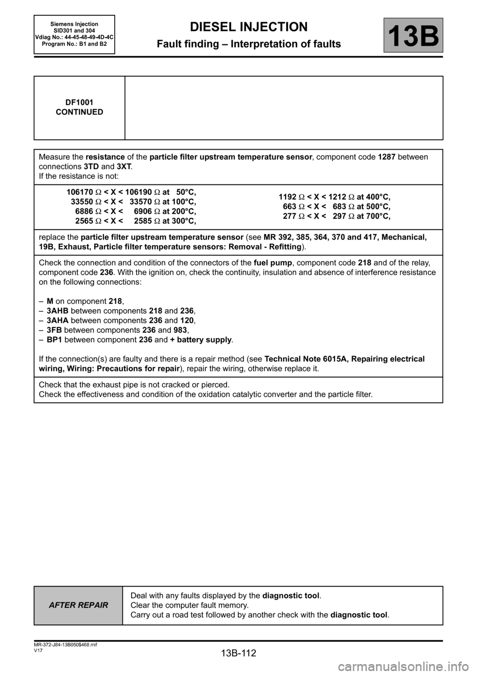
DF1001
CONTINUED
Measure the resistance of the particle filter upstream temperature sensor, component code 1287 between
connections 3TD and 3XT.
If the resistance is not:
106170Ω
6886Ω < X < 6906Ω at 200°C,
2565Ω < X < 2585Ω at 300°C,1192Ω
19B, Exhaust, Particle filter temperature sensors: Removal - Refitting).
Check the connection and condition of the connectors of the fuel pump, component code 218 and of the relay,
component code 236. With the ignition on, check the continuity, insulation and absence of interference resistance
on the following connections:
–M on component 218,
–3AHB between components 218 and 236,
–3AHA between components 236 and 120,
–3FB between components236 and 983,
–BP1 between component 236 and + battery supply
.
If the connection(s) are faulty and there is a repair method (see Technical Note 6015A, Repairing electrical
wiring, Wiring: Precautions for repair), repair the wiring, otherwise replace it.
Check that the exhaust pipe is not cracked or pierced.
Check the effectiveness and condition of the oxidation catalytic converter and the particle filter.
AFTER REPAIRDeal with any faults displayed by the diagnostic tool.
Clear the computer fault memory.
Carry out a road test followed by another check with the diagnostic tool.
Page 113 of 329
13B-113
MR-372-J84-13B050$468.mif
V17
DIESEL INJECTION
Fault finding – Interpretation of faults
Siemens Injection
SID301 and 304
Vdiag No.: 44-45-48-49-4D-4C
Program No.: B1 and B2
13B
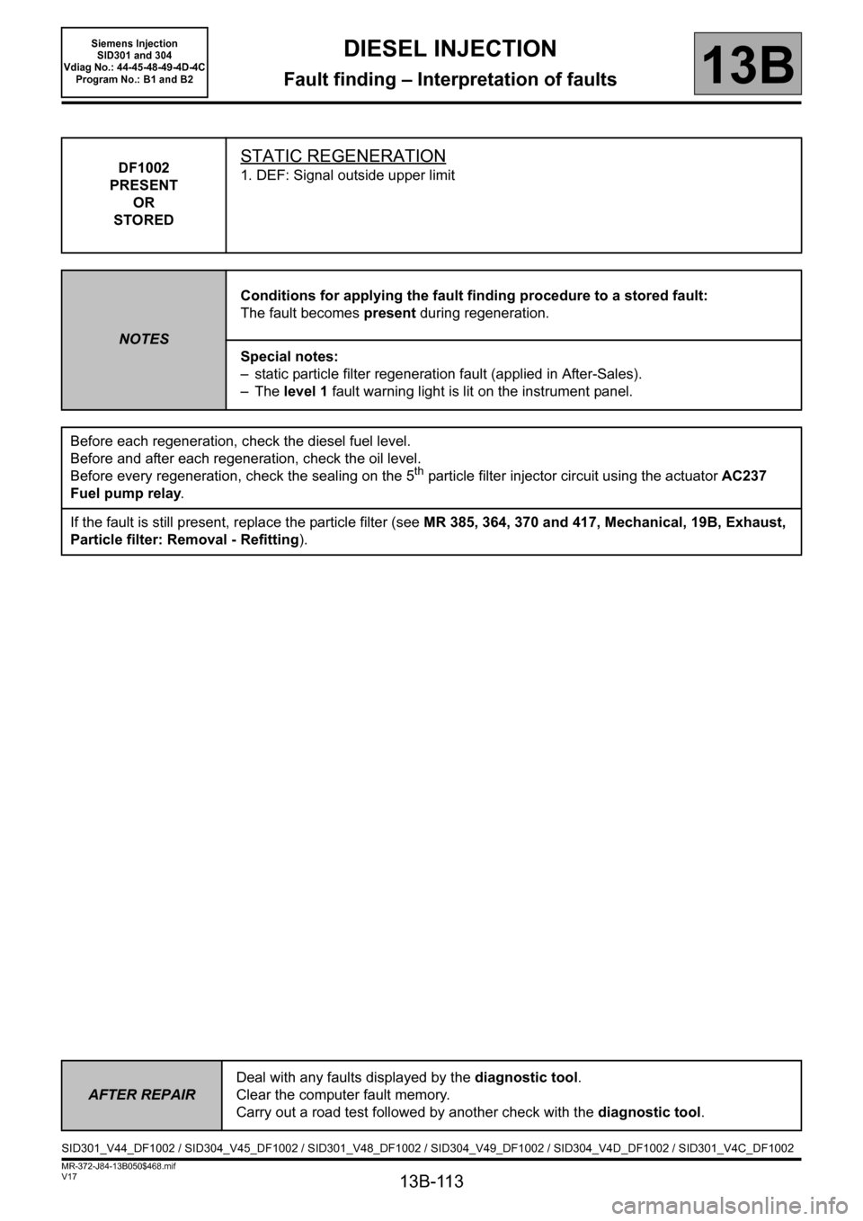
DF1002
PRESENT
OR
STOREDSTATIC REGENERATION
1. DEF: Signal outside upper limit
NOTESConditions for applying the fault finding procedure to a stored fault:
The fault becomes present during regeneration.
Special notes:
– static particle filter regeneration fault (applied in After-Sales).
–The level 1 fault warning light is lit on the instrument panel.
Before each regeneration, check the diesel fuel level.
Before and after each regeneration, check the oil level.
Before every regeneration, check the sealing on the 5
th particle filter injector circuit using the actuator AC237
Fuel pump relay.
If the fault is still present, replace the particle filter (see MR 385, 364, 370 and 417, Mechanical, 19B, Exhaust,
Particle filter: Removal - Refitting).
AFTER REPAIRDeal with any faults displayed by the diagnostic tool.
Clear the computer fault memory.
Carry out a road test followed by another check with the diagnostic tool.
SID301_V44_DF1002 / SID304_V45_DF1002 / SID301_V48_DF1002 / SID304_V49_DF1002 / SID304_V4D_DF1002 / SID301_V4C_DF1002
Page 126 of 329
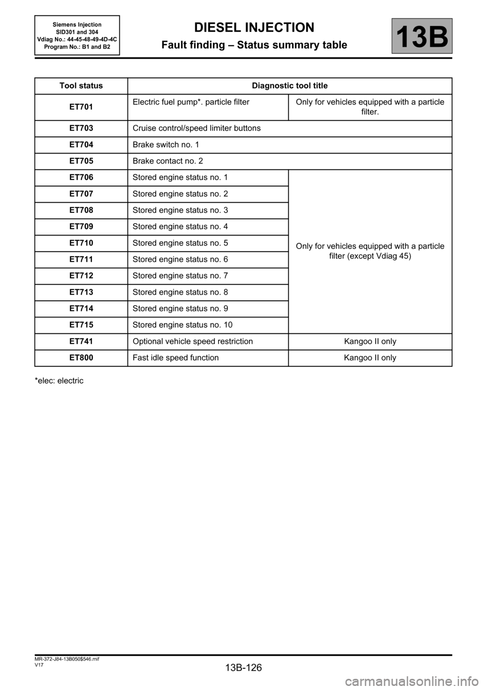
13B-126
MR-372-J84-13B050$546.mif
V17
Siemens Injection
SID301 and 304
Vdiag No.: 44-45-48-49-4D-4C
Program No.: B1 and B2DIESEL INJECTION
Fault finding – Status summary table13B
*elec: electricTool status Diagnostic tool title
ET701Electric fuel pump*. particle filter Only for vehicles equipped with a particle
filter.
ET703Cruise control/speed limiter buttons
ET704Brake switch no. 1
ET705Brake contact no. 2
ET706Stored engine status no. 1
Only for vehicles equipped with a particle
filter (except Vdiag 45) ET707Stored engine status no. 2
ET708Stored engine status no. 3
ET709Stored engine status no. 4
ET710Stored engine status no. 5
ET711Stored engine status no. 6
ET712Stored engine status no. 7
ET713Stored engine status no. 8
ET714Stored engine status no. 9
ET715Stored engine status no. 10
ET741Optional vehicle speed restriction Kangoo II only
ET800Fast idle speed function Kangoo II only
Page 176 of 329
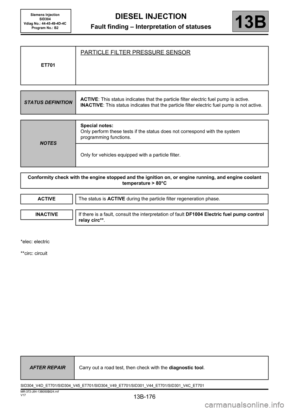
13B-176
MR-372-J84-13B050$624.mif
V17
13B
DIESEL INJECTION
Fault finding – Interpretation of statuses
*elec: electric
**circ: circuitET701
PARTICLE FILTER PRESSURE SENSOR
STATUS DEFINITIONACTIVE: This status indicates that the particle filter electric fuel pump is active.
INACTIVE: This status indicates that the particle filter electric fuel pump is not active.
NOTESSpecial notes:
Only perform these tests if the status does not correspond with the system
programming functions.
Only for vehicles equipped with a particle filter.
Conformity check with the engine stopped and the ignition on, or engine running, and engine coolant
temperature > 80°C
ACTIVE
INACTIVE
The status is ACTIVE during the particle filter regeneration phase.
If there is a fault, consult the interpretation of fault DF1004 Electric fuel pump control
relay circ**.
AFTER REPAIRCarry out a road test, then check with the diagnostic tool.
SID304_V4D_ET701/SID304_V45_ET701/SID304_V49_ET701/SID301_V44_ET701/SID301_V4C_ET701
Siemens Injection
SID304
Vdiag No.: 44-45-49-4D-4C
Program No.: B2