fuel pressure RENAULT SCENIC 2011 J95 / 3.G Engine And Peripherals Siemens Injection Repair Manual
[x] Cancel search | Manufacturer: RENAULT, Model Year: 2011, Model line: SCENIC, Model: RENAULT SCENIC 2011 J95 / 3.GPages: 329, PDF Size: 1.71 MB
Page 307 of 329
13B-307
MR-372-J84-13B050$936.mif
V17
Siemens Injection
SID301 and 304
Vdiag No.: 44-45-48-49-4D-4C
Program No.: B1 and B2DIESEL INJECTION
Fault finding – Tests13B
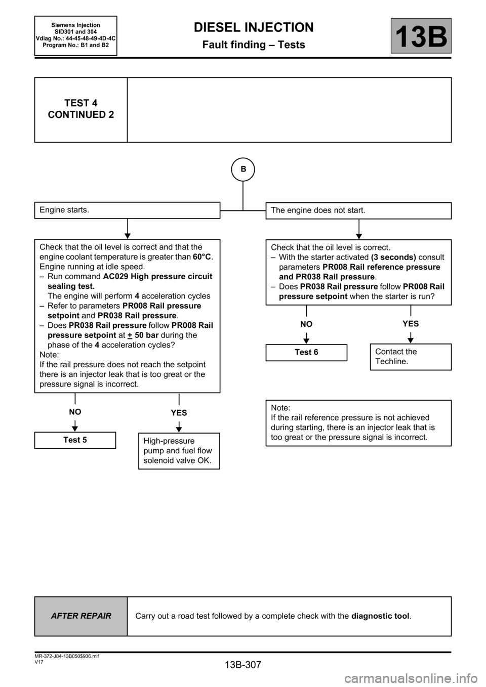
TEST 4
CONTINUED 2
Engine starts.
Check that the oil level is correct and that the
engine coolant temperature is greater than 60°C.
Engine running at idle speed.
– Run command AC029 High pressure circuit
sealing test.
The engine will perform 4acceleration cycles
– Refer to parameters PR008 Rail pressure
setpoint and PR038 Rail pressure.
–Does PR038 Rail pressure follow PR008 Rail
pressure setpoint at +
50 bar during the
phase of the 4 acceleration cycles?
Note:
If the rail pressure does not reach the setpoint
there is an injector leak that is too great or the
pressure signal is incorrect.
NO
Test 5
YES
High-pressure
pump and fuel flow
solenoid valve OK.
The engine does not start.
Check that the oil level is correct.
– With the starter activated (3 seconds) consult
parameters PR008 Rail reference pressure
and PR038 Rail pressure.
–Does PR038 Rail pressure follow PR008 Rail
pressure setpoint when the starter is run?
NO
Test 6
YES
Contact the
Techline.
Note:
If the rail reference pressure is not achieved
during starting, there is an injector leak that is
too great or the pressure signal is incorrect.
AFTER REPAIRCarry out a road test followed by a complete check with the diagnostic tool.
B
Page 308 of 329
13B-308
MR-372-J84-13B050$936.mif
V17
DIESEL INJECTION
Fault finding – Tests13B
Siemens Injection
SID301 and 304
Vdiag No.: 44-45-48-49-4D-4C
Program No.: B1 and B2
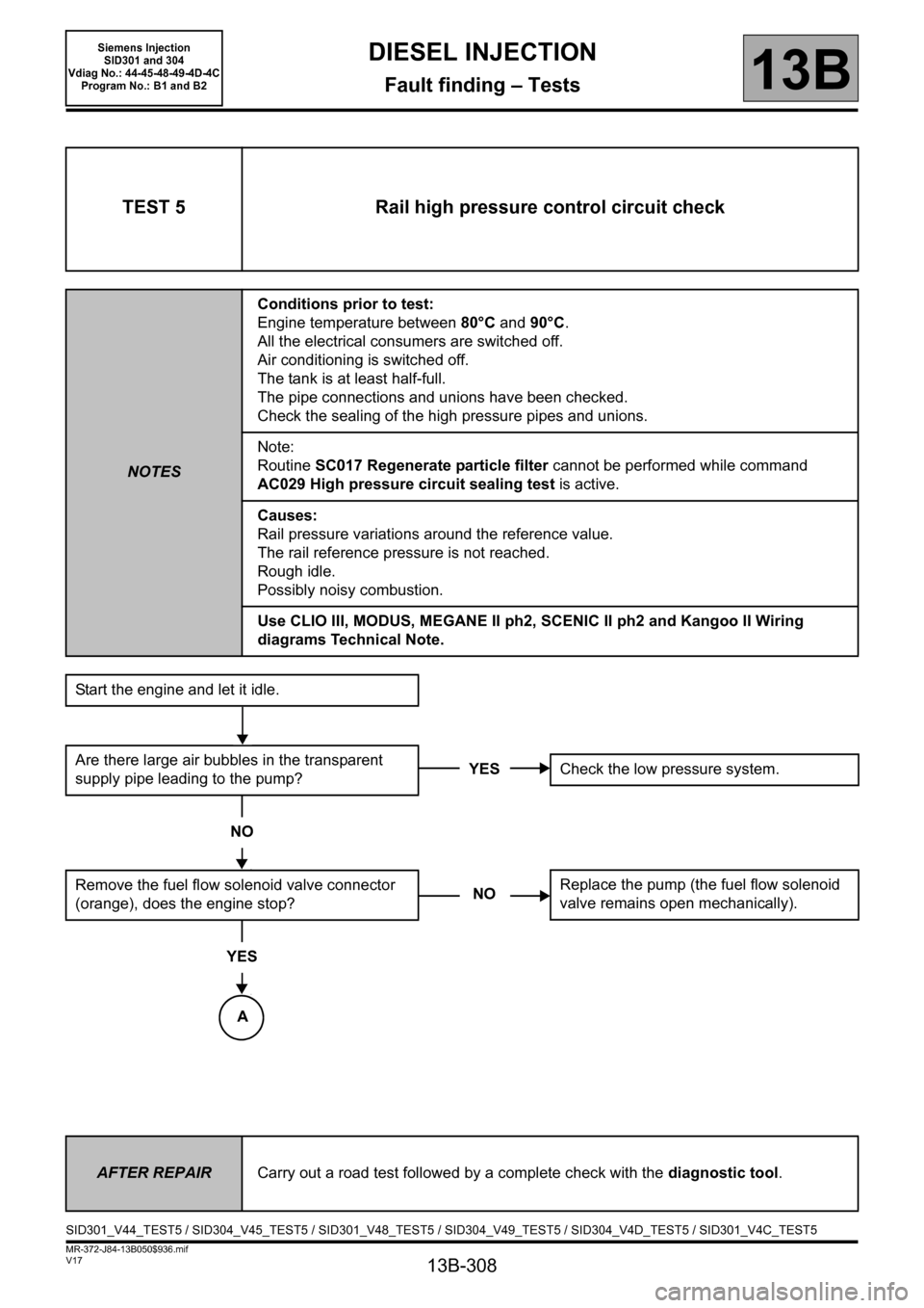
TEST 5 Rail high pressure control circuit check
NOTESConditions prior to test:
Engine temperature between 80°C and 90°C.
All the electrical consumers are switched off.
Air conditioning is switched off.
The tank is at least half-full.
The pipe connections and unions have been checked.
Check the sealing of the high pressure pipes and unions.
Note:
Routine SC017 Regenerate particle filter cannot be performed while command
AC029 High pressure circuit sealing test is active.
Causes:
Rail pressure variations around the reference value.
The rail reference pressure is not reached.
Rough idle.
Possibly noisy combustion.
Use CLIO III, MODUS, MEGANE II ph2, SCENIC II ph2 and Kangoo II Wiring
diagrams Technical Note.
Start the engine and let it idle.
Are there large air bubbles in the transparent
supply pipe leading to the pump?
NO
Remove the fuel flow solenoid valve connector
(orange), does the engine stop?
YES
YESCheck the low pressure system.
NOReplace the pump (the fuel flow solenoid
valve remains open mechanically).
AFTER REPAIRCarry out a road test followed by a complete check with the diagnostic tool.
SID301_V44_TEST5 / SID304_V45_TEST5 / SID301_V48_TEST5 / SID304_V49_TEST5 / SID304_V4D_TEST5 / SID301_V4C_TEST5
A
Page 309 of 329
13B-309
MR-372-J84-13B050$936.mif
V17
DIESEL INJECTION
Fault finding – Tests13B
Siemens Injection
SID301 and 304
Vdiag No.: 44-45-48-49-4D-4C
Program No.: B1 and B2
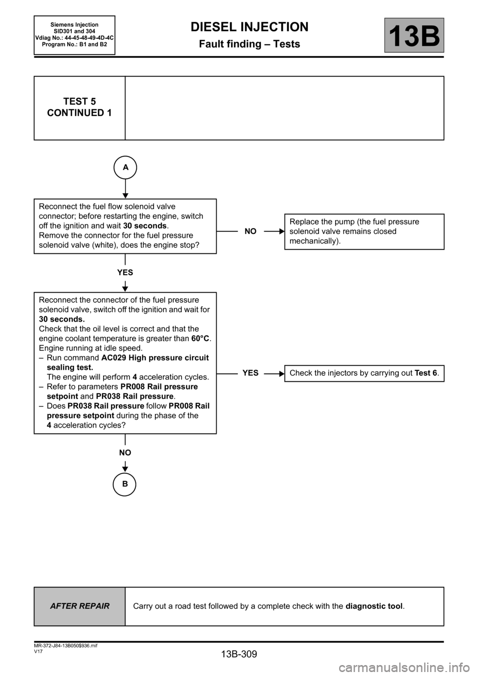
TEST 5
CONTINUED 1
Reconnect the fuel flow solenoid valve
connector; before restarting the engine, switch
off the ignition and wait 30 seconds.
Remove the connector for the fuel pressure
solenoid valve (white), does the engine stop?
YES
Reconnect the connector of the fuel pressure
solenoid valve, switch off the ignition and wait for
30 seconds.
Check that the oil level is correct and that the
engine coolant temperature is greater than 60°C.
Engine running at idle speed.
– Run command AC029 High pressure circuit
sealing test.
The engine will perform 4acceleration cycles.
– Refer to parameters PR008 Rail pressure
setpoint and PR038 Rail pressure.
–Does PR038 Rail pressure follow PR008 Rail
pressure setpoint during the phase of the
4acceleration cycles?
NO
NOReplace the pump (the fuel pressure
solenoid valve remains closed
mechanically).
YESCheck the injectors by carrying out Te s t 6.
AFTER REPAIRCarry out a road test followed by a complete check with the diagnostic tool.
A
B
Page 310 of 329
13B-310
MR-372-J84-13B050$936.mif
V17
DIESEL INJECTION
Fault finding – Tests13B
Siemens Injection
SID301 and 304
Vdiag No.: 44-45-48-49-4D-4C
Program No.: B1 and B2
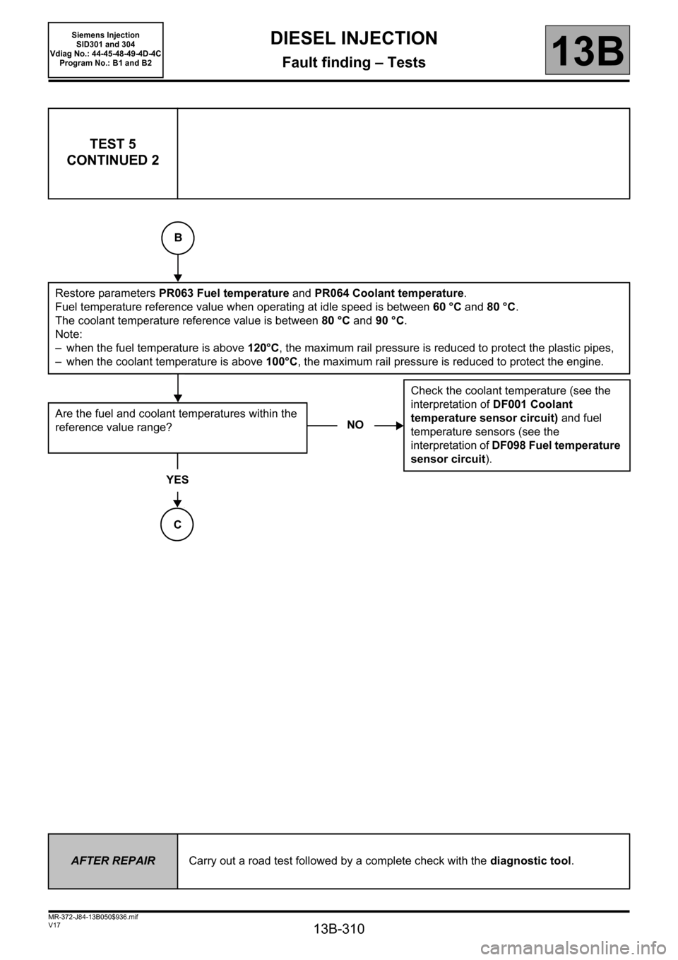
TEST 5
CONTINUED 2
Restore parameters PR063 Fuel temperature and PR064 Coolant temperature.
Fuel temperature reference value when operating at idle speed is between 60 °C and 80 °C.
The coolant temperature reference value is between 80 °C and 90 °C.
Note:
– when the fuel temperature is above 120°C, the maximum rail pressure is reduced to protect the plastic pipes,
– when the coolant temperature is above 100°C, the maximum rail pressure is reduced to protect the engine.
Are the fuel and coolant temperatures within the
reference value range?
YES
NOCheck the coolant temperature (see the
interpretation of DF001 Coolant
temperature sensor circuit) and fuel
temperature sensors (see the
interpretation of DF098 Fuel temperature
sensor circuit).
AFTER REPAIRCarry out a road test followed by a complete check with the diagnostic tool.
B
C
Page 311 of 329
13B-311
MR-372-J84-13B050$936.mif
V17
DIESEL INJECTION
Fault finding – Tests13B
Siemens Injection
SID301 and 304
Vdiag No.: 44-45-48-49-4D-4C
Program No.: B1 and B2
TEST 5
CONTINUED 3
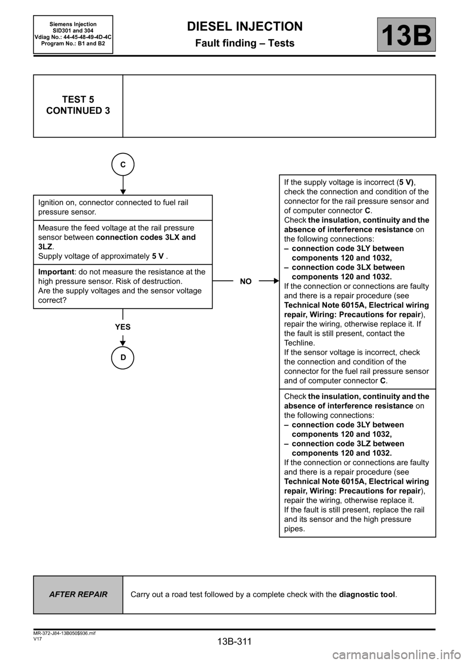
Ignition on, connector connected to fuel rail
pressure sensor.
Measure the feed voltage at the rail pressure
sensor between connection codes 3LX and
3LZ.
Supply voltage of approximately 5V .
Important: do not measure the resistance at the
high pressure sensor. Risk of destruction.
Are the supply voltages and the sensor voltage
correct?
YES
NOIf the supply voltage is incorrect (5 V),
check the connection and condition of the
connector for the rail pressure sensor and
of computer connector C.
Check the insulation, continuity and the
absence of interference resistance on
the following connections:
– connection code 3LY between
components 120 and 1032,
– connection code 3LX between
components 120 and 1032.
If the connection or connections are faulty
and there is a repair procedure (see
Technical Note 6015A, Electrical wiring
repair, Wiring: Precautions for repair),
repair the wiring, otherwise replace it. If
the fault is still present, contact the
Techline.
If the sensor voltage is incorrect, check
the connection and condition of the
connector for the fuel rail pressure sensor
and of computer connector C.
Check the insulation, continuity and the
absence of interference resistance on
the following connections:
– connection code 3LY between
components 120 and 1032,
– connection code 3LZ between
components 120 and 1032.
If the connection or connections are faulty
and there is a repair procedure (see
Technical Note 6015A, Electrical wiring
repair, Wiring: Precautions for repair),
repair the wiring, otherwise replace it.
If the fault is still present, replace the rail
and its sensor and the high pressure
pipes.
AFTER REPAIRCarry out a road test followed by a complete check with the diagnostic tool.
C
D
Page 313 of 329
13B-313
MR-372-J84-13B050$936.mif
V17
DIESEL INJECTION
Fault finding – Tests13B
Siemens Injection
SID301 and 304
Vdiag No.: 44-45-48-49-4D-4C
Program No.: B1 and B2
TEST 6 Major leak in injectors/injectors open
NOTESConditions prior to test:
The entire low pressure system must be in good condition.
Check the sealing of the high pressure pipes and unions.
Te s t 3 High pressure fuel pressure solenoid valve check is OK.
Test 4 High pressure pump (HPP) and fuel flow solenoid valve check is OK.
Te s t 5 Rail high pressure regulation circuit check is OK.
Causes:
Not enough or no rail pressure during starting.
The engine does not start.
Use CLIO III, MODUS, MEGANE II ph2, SCENIC II ph2 and Kangoo II Wiring
diagrams Technical Note.
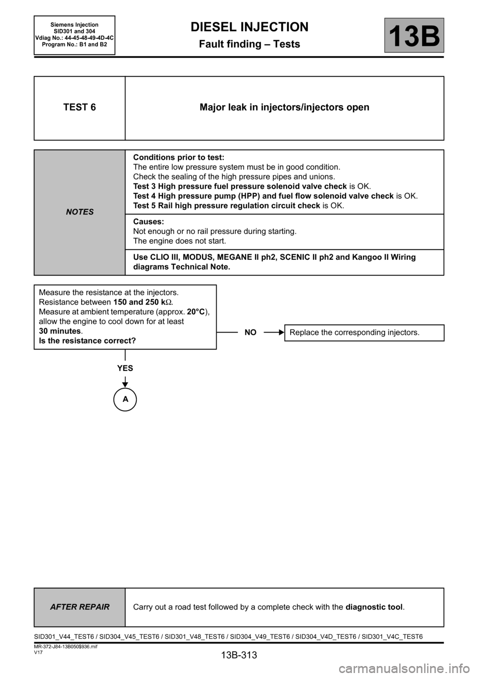
Measure the resistance at the injectors.
Resistance between 150 and 250 kΩ.
Measure at ambient temperature (approx. 20°C),
allow the engine to cool down for at least
30 minutes.
Is the resistance correct?
YES
NOReplace the corresponding injectors.
AFTER REPAIRCarry out a road test followed by a complete check with the diagnostic tool.
SID301_V44_TEST6 / SID304_V45_TEST6 / SID301_V48_TEST6 / SID304_V49_TEST6 / SID304_V4D_TEST6 / SID301_V4C_TEST6
A
Page 315 of 329
13B-315
MR-372-J84-13B050$936.mif
V17
DIESEL INJECTION
Fault finding – Tests13B
Siemens Injection
SID301 and 304
Vdiag No.: 44-45-48-49-4D-4C
Program No.: B1 and B2
TEST 6
CONTINUED 2
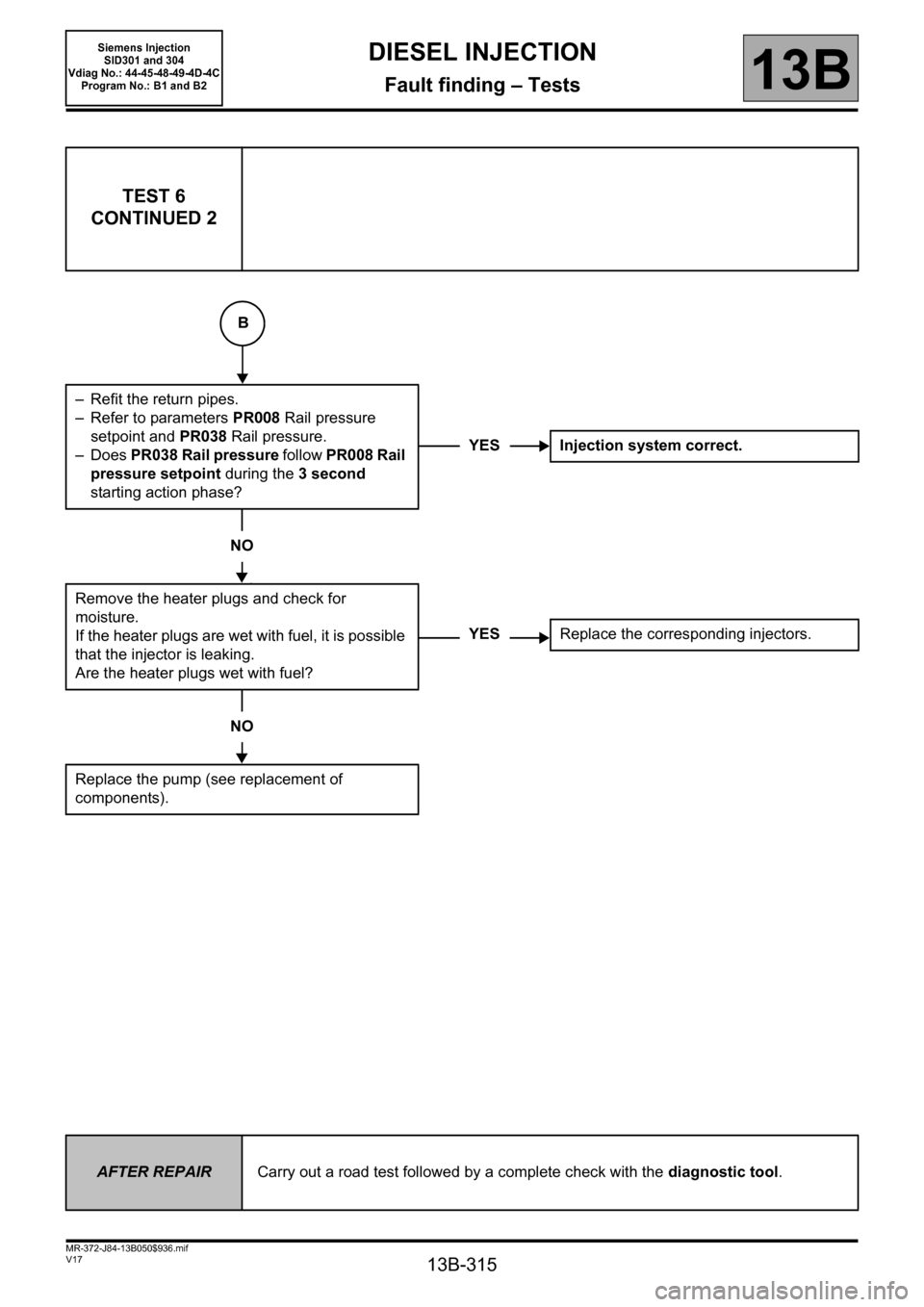
– Refit the return pipes.
– Refer to parameters PR008 Rail pressure
setpoint and PR038 Rail pressure.
–Does PR038 Rail pressure follow PR008 Rail
pressure setpoint during the 3second
starting action phase?
NO
Remove the heater plugs and check for
moisture.
If the heater plugs are wet with fuel, it is possible
that the injector is leaking.
Are the heater plugs wet with fuel?
NO
Replace the pump (see replacement of
components).
YES Injection system correct.
YESReplace the corresponding injectors.
AFTER REPAIRCarry out a road test followed by a complete check with the diagnostic tool.
B
Page 316 of 329
13B-316
MR-372-J84-13B050$936.mif
V17
DIESEL INJECTION
Fault finding – Tests13B
Siemens Injection
SID301 and 304
Vdiag No.: 44-45-48-49-4D-4C
Program No.: B1 and B2
TEST 7 Incorrect injection quantity
NOTESConditions prior to test:
The entire low pressure system must be in good condition.
Check the sealing of the high pressure pipes and unions.
Te s t 3 High pressure fuel pressure solenoid valve check is OK.
Test 4 High pressure pump (HPP) and fuel flow solenoid valve check is OK.
Te s t 5 Rail high pressure regulation circuit check is OK.
All the electrical consumers are switched off.
Air conditioning is switched off.
Cause:
The engine runs poorly at idle speed, possibly emits white smoke.
Use CLIO III, MODUS, MEGANE II ph2, SCENIC II ph2 and KANGOO II Wiring
diagrams Technical Note.
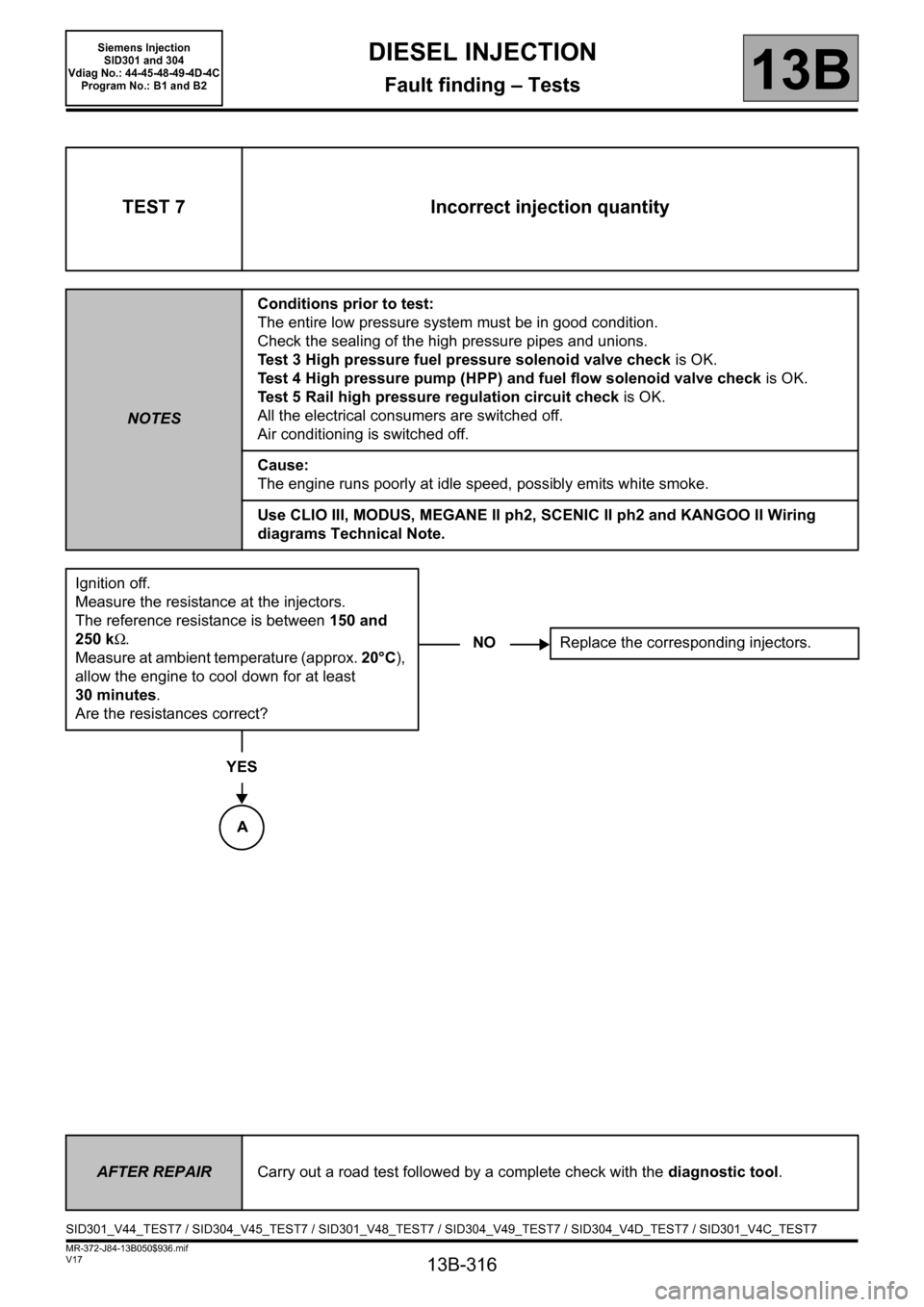
Ignition off.
Measure the resistance at the injectors.
The reference resistance is between 150 and
250 kΩ.
Measure at ambient temperature (approx. 20°C),
allow the engine to cool down for at least
30 minutes.
Are the resistances correct?
YES
NOReplace the corresponding injectors.
AFTER REPAIRCarry out a road test followed by a complete check with the diagnostic tool.
SID301_V44_TEST7 / SID304_V45_TEST7 / SID301_V48_TEST7 / SID304_V49_TEST7 / SID304_V4D_TEST7 / SID301_V4C_TEST7
A
Page 319 of 329
13B-319
MR-372-J84-13B050$936.mif
V17
DIESEL INJECTION
Fault finding – Tests
Siemens Injection
SID301 and 304
Vdiag No.: 44-45-48-49-4D-4C
Program No.: B1 and B2
13B
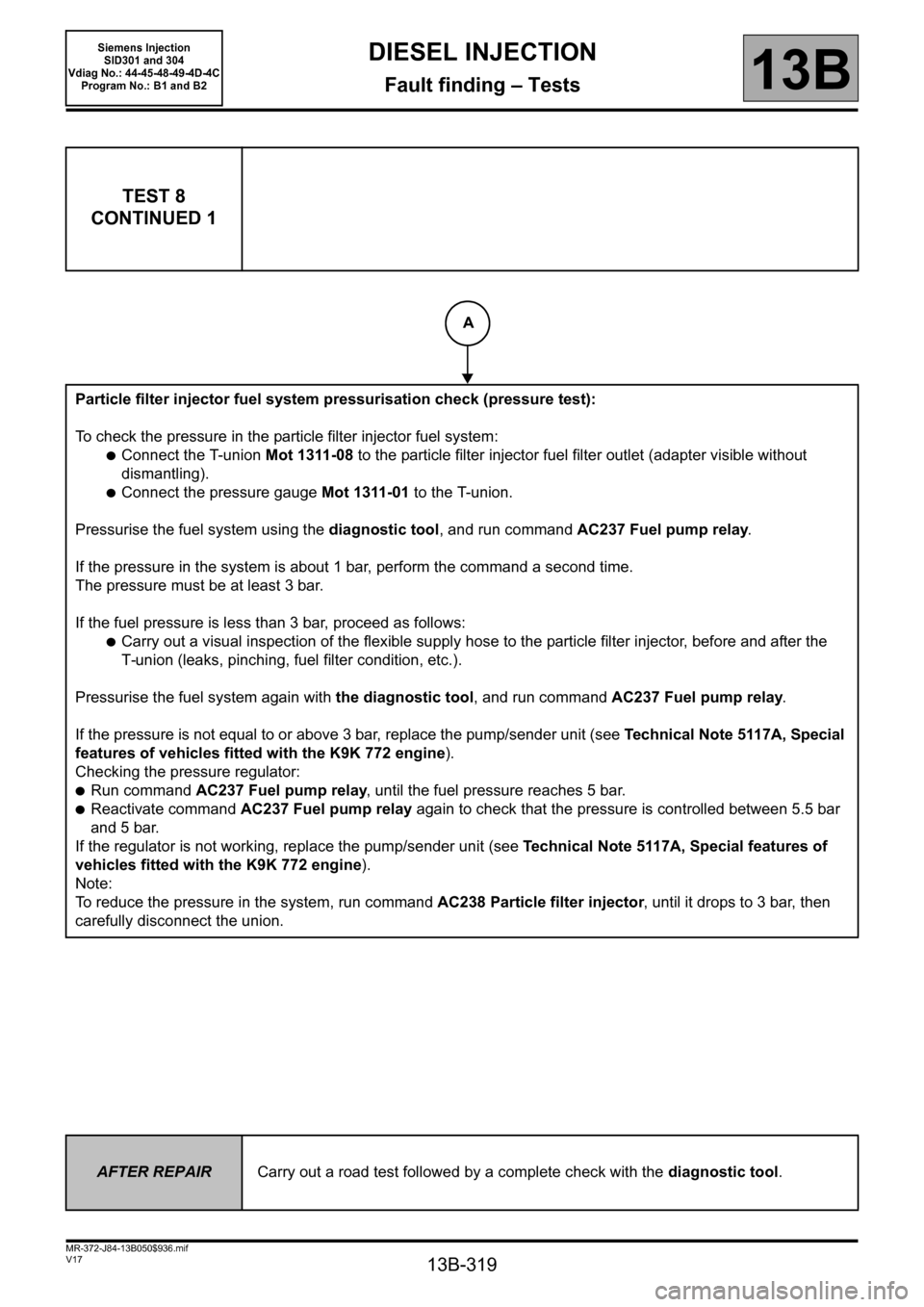
TEST 8
CONTINUED 1
Particle filter injector fuel system pressurisation check (pressure test):
To check the pressure in the particle filter injector fuel system:
●Connect the T-union Mot 1311-08 to the particle filter injector fuel filter outlet (adapter visible without
dismantling).
●Connect the pressure gauge Mot 1311-01 to the T-union.
Pressurise the fuel system using the diagnostic tool, and run command AC237 Fuel pump relay.
If the pressure in the system is about 1 bar, perform the command a second time.
The pressure must be at least 3 bar.
If the fuel pressure is less than 3 bar, proceed as follows:
●Carry out a visual inspection of the flexible supply hose to the particle filter injector, before and after the
T-union (leaks, pinching, fuel filter condition, etc.).
Pressurise the fuel system again with the diagnostic tool, and run command AC237 Fuel pump relay.
If the pressure is not equal to or above 3 bar, replace the pump/sender unit (see Technical Note 5117A, Special
features of vehicles fitted with the K9K 772 engine).
Checking the pressure regulator:
●Run command AC237 Fuel pump relay, until the fuel pressure reaches 5 bar.
●Reactivate command AC237 Fuel pump relay again to check that the pressure is controlled between 5.5 bar
and 5 bar.
If the regulator is not working, replace the pump/sender unit (see Technical Note 5117A, Special features of
vehicles fitted with the K9K 772 engine).
Note:
To reduce the pressure in the system, run command AC238 Particle filter injector, until it drops to 3 bar, then
carefully disconnect the union.
AFTER REPAIRCarry out a road test followed by a complete check with the diagnostic tool.
A
Page 320 of 329
13B-320
MR-372-J84-13B050$936.mif
V17
DIESEL INJECTION
Fault finding – Tests
Siemens Injection
SID301 and 304
Vdiag No.: 44-45-48-49-4D-4C
Program No.: B1 and B2
13B
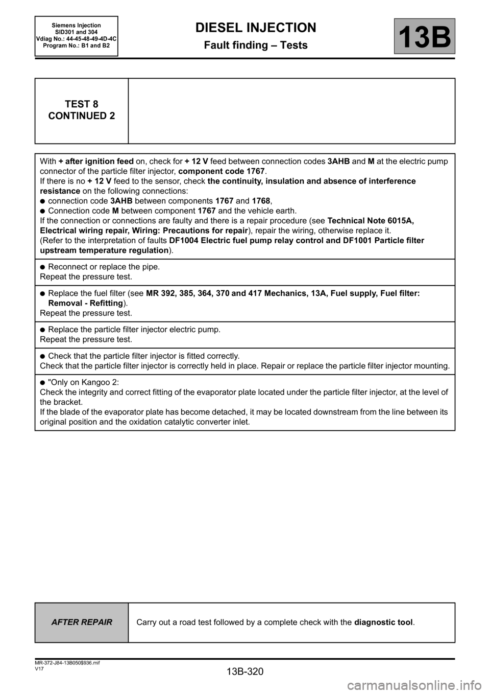
TEST 8
CONTINUED 2
With + after ignition feed on, check for + 12 V feed between connection codes 3AHB and M at the electric pump
connector of the particle filter injector, component code 1767.
If there is no + 12 V feed to the sensor, check the continuity, insulation and absence of interference
resistance on the following connections:
●connection code 3AHB between components 1767 and 1768,
●Connection code M between component 1767 and the vehicle earth.
If the connection or connections are faulty and there is a repair procedure (see Technical Note 6015A,
Electrical wiring repair, Wiring: Precautions for repair), repair the wiring, otherwise replace it.
(Refer to the interpretation of faults DF1004 Electric fuel pump relay control and DF1001 Particle filter
upstream temperature regulation).
●Reconnect or replace the pipe.
Repeat the pressure test.
●Replace the fuel filter (see MR 392, 385, 364, 370 and 417 Mechanics, 13A, Fuel supply, Fuel filter:
Removal - Refitting).
Repeat the pressure test.
●Replace the particle filter injector electric pump.
Repeat the pressure test.
●Check that the particle filter injector is fitted correctly.
Check that the particle filter injector is correctly held in place. Repair or replace the particle filter injector mounting.
●"Only on Kangoo 2:
Check the integrity and correct fitting of the evaporator plate located under the particle filter injector, at the level of
the bracket.
If the blade of the evaporator plate has become detached, it may be located downstream from the line between its
original position and the oxidation catalytic converter inlet.
AFTER REPAIRCarry out a road test followed by a complete check with the diagnostic tool.