ABS RENAULT SCENIC 2011 J95 / 3.G Engine And Peripherals Siemens Injection Repair Manual
[x] Cancel search | Manufacturer: RENAULT, Model Year: 2011, Model line: SCENIC, Model: RENAULT SCENIC 2011 J95 / 3.GPages: 329, PDF Size: 1.71 MB
Page 117 of 329
13B-117
MR-372-J84-13B050$468.mif
V17
DIESEL INJECTION
Fault finding – Interpretation of faults
Siemens Injection
SID301 and 304
Vdiag No.: 44-45-48-49-4D-4C
Program No.: B1 and B2
13B
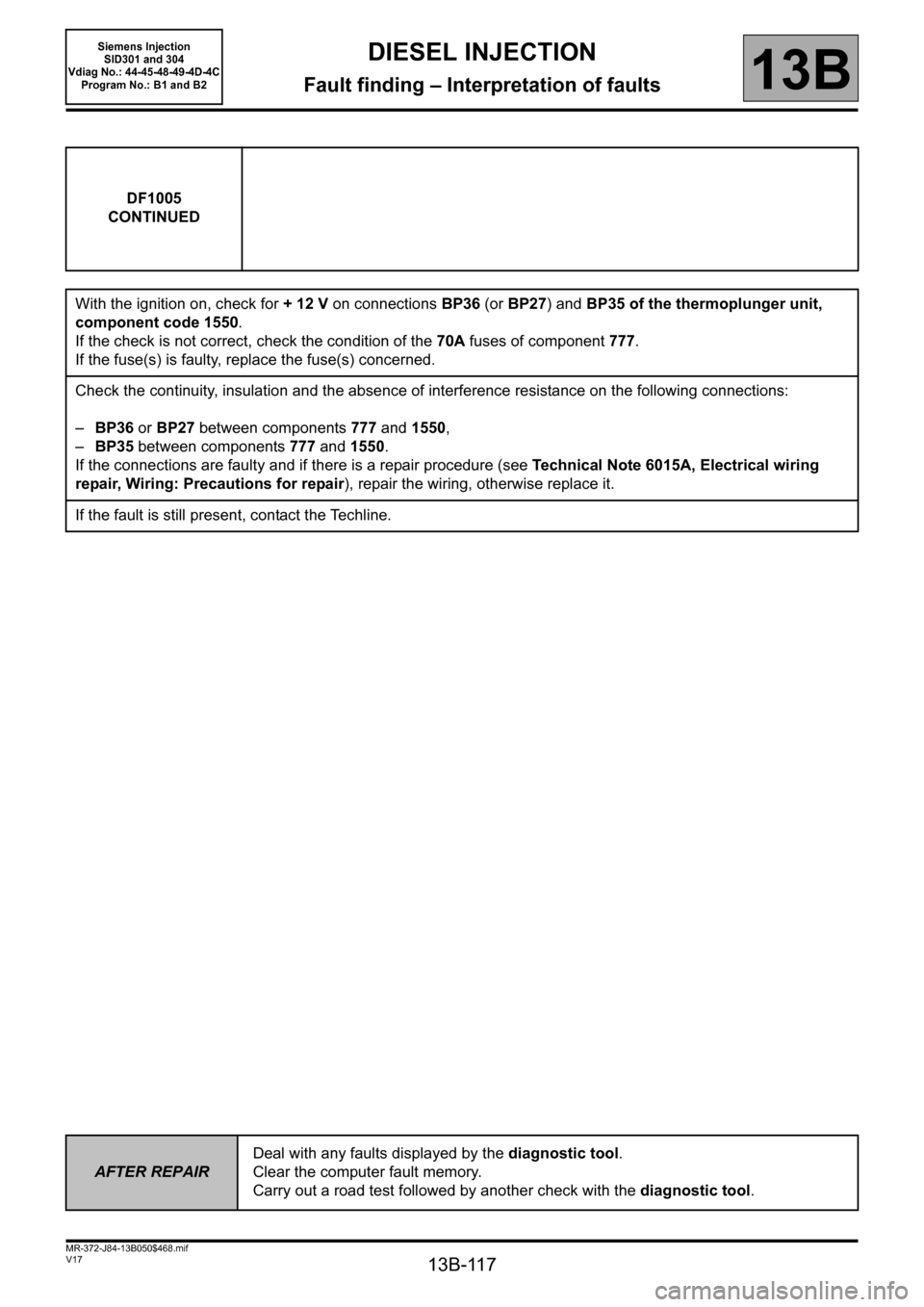
DF1005
CONTINUED
With the ignition on, check for + 12 V on connections BP36 (or BP27) and BP35 of the thermoplunger unit,
component code 1550.
If the check is not correct, check the condition of the 70A fuses of component 777.
If the fuse(s) is faulty, replace the fuse(s) concerned.
Check the continuity, insulation and the absence of interference resistance on the following connections:
– BP36 or BP27 between components 777 and 1550,
– BP35 between components 777 and 1550.
If the connections are faulty and if there is a repair procedure (see Technical Note 6015A, Electrical wiring
repair, Wiring: Precautions for repair), repair the wiring, otherwise replace it.
If the fault is still present, contact the Techline.
AFTER REPAIRDeal with any faults displayed by the diagnostic tool.
Clear the computer fault memory.
Carry out a road test followed by another check with the diagnostic tool.
Page 119 of 329
13B-119
MR-372-J84-13B050$468.mif
V17
DIESEL INJECTION
Fault finding – Interpretation of faults
Siemens Injection
SID301 and 304
Vdiag No.: 44-45-48-49-4D-4C
Program No.: B1 and B2
13B
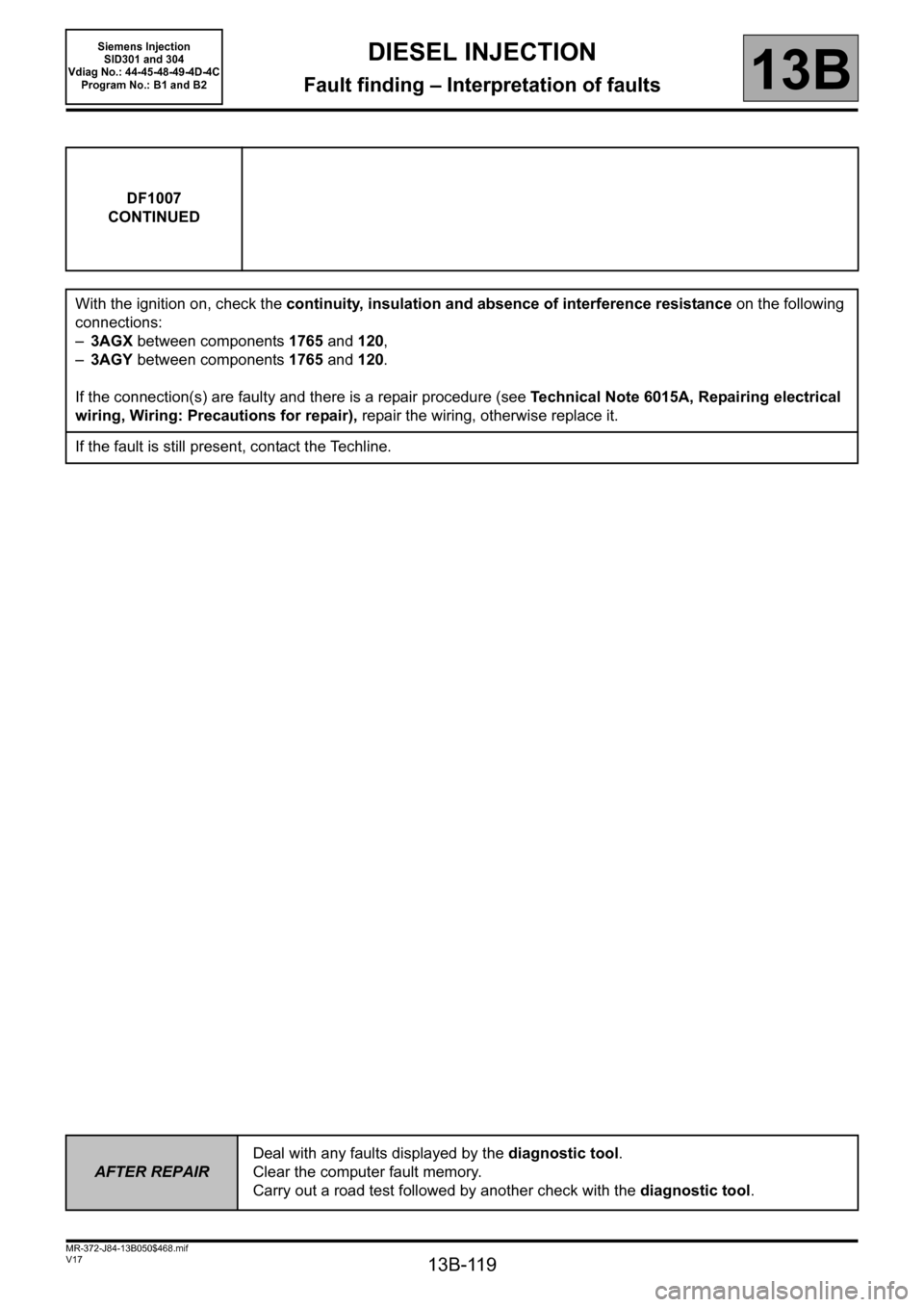
DF1007
CONTINUED
With the ignition on, check the continuity, insulation and absence of interference resistance on the following
connections:
–3AGX between components 1765 and 120,
–3AGY between components 1765 and 120.
If the connection(s) are faulty and there is a repair procedure (see Technical Note 6015A, Repairing electrical
wiring, Wiring: Precautions for repair), repair the wiring, otherwise replace it.
If the fault is still present, contact the Techline.
AFTER REPAIRDeal with any faults displayed by the diagnostic tool.
Clear the computer fault memory.
Carry out a road test followed by another check with the diagnostic tool.
Page 120 of 329
13B-120
MR-372-J84-13B050$468.mif
V17
DIESEL INJECTION
Fault finding – Interpretation of faults
Siemens Injection
SID301 and 304
Vdiag No.: 44-45-48-49-4D-4C
Program No.: B1 and B2
13B
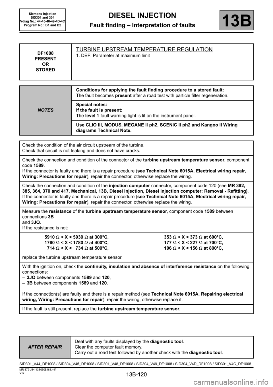
DF1008
PRESENT
OR
STOREDTURBINE UPSTREAM TEMPERATURE REGULATION
1. DEF: Parameter at maximum limit
NOTESConditions for applying the fault finding procedure to a stored fault:
The fault becomes present after a road test with particle filter regeneration.
Special notes:
If the fault is present:
The level 1 fault warning light is lit on the instrument panel.
Use CLIO III, MODUS, MEGANE II ph2, SCENIC II ph2 and Kangoo II Wiring
diagrams Technical Note.
Check the condition of the air circuit upstream of the turbine.
Check that circuit is not leaking and does not have cracks.
Check the connection and condition of the connector of the turbine upstream temperature sensor, component
code 1589.
If the connector is faulty and there is a repair procedure (see Technical Note 6015A, Electrical wiring repair,
Wiring: Precautions for repair), repair the connector, otherwise replace the wiring.
Check the connection and condition of the injection computer connector, component code 120 (see MR 392,
385, 364, 370 and 417, Mechanical, 13B, Diesel injection, Diesel injection computer: Removal - Refitting).
If the connector is faulty and there is a repair procedure (see Technical Note 6015A, Electrical wiring repair,
Wiring: Precautions for repair), repair the connector, otherwise replace the wiring.
Measure the resistance of the turbine upstream temperature sensor, component code 1589 between
connections 3B
and 3JQ.
If the resistance is not:
5910Ω < X < 5930Ω at 300°C,
1760Ω < X < 1780Ω at 400°C,
714Ω < X < 734Ω at 500°C,353Ω < X < 373Ω at 600°C,
177Ω < X < 227Ω at 700°C,
106Ω < X < 156Ω at 800°C,
replace the turbine upstream temperature sensor.
With the ignition on, check the continuity, insulation and absence of interference resistance on the following
connections:
–3JQ between components 1589 and 120,
–3B between components 1589 and 120.
If the connection(s) are faulty and there is a repair method (see
Technical Note 6015A, Repairing electrical
wiring, Wiring: Precautions for repair), repair the wiring, otherwise replace it.
If the fault is still present, replace the turbine upstream temperature sensor.
AFTER REPAIRDeal with any faults displayed by the diagnostic tool.
Clear the computer fault memory.
Carry out a road test followed by another check with the diagnostic tool.
SID301_V44_DF1008 / SID304_V45_DF1008 / SID301_V48_DF1008 / SID304_V49_DF1008 / SID304_V4D_DF1008 / SID301_V4C_DF1008
Page 121 of 329

13B-121
MR-372-J84-13B050$468.mif
V17
DIESEL INJECTION
Fault finding – Interpretation of faults
Siemens Injection
SID301 and 304
Vdiag No.: 44-45-48-49-4D-4C
Program No.: B1 and B2
13B
DF1009
PRESENT
OR
STOREDCATALYTIC CONVERTER 1 DOWNSTREAM TEMPERATURE
REGULATION
1. DEF: Signal outside lower limit
2. DEF: Signal outside upper limit
NOTESConditions for applying the fault finding procedure to a stored fault:
The fault becomes present after a road test with particle filter regeneration.
Special notes:
If the fault is present:
The level 1 fault warning light is lit on the instrument panel.
Use CLIO III, MODUS, MEGANE II ph2, SCENIC II ph2 and Kangoo II Wiring
diagrams Technical Note.
Check the connection and condition of the connector of the catalytic converter 1 downstream temperature
sensor, component code 1765.
If the connector is faulty and there is a repair procedure (see Technical Note 6015A, Electrical wiring repair,
Wiring: Precautions for repair), repair the connector, otherwise replace the wiring.
Check the connection and condition of the injection computer connector, component code 120 (see MR 392,
385, 364, 370 and 417, Mechanical, 13B, Diesel injection, Diesel injection computer: Removal - Refitting).
If the connector is faulty and there is a repair procedure (see Technical Note 6015A, Electrical wiring repair,
Wiring: Precautions for repair), repair the connector, otherwise replace the wiring.
With the ignition on, check the continuity, insulation and absence of interference resistance on the following
connections:
–3AGX between components 1765 and 120,
–3AGY between components 1765 and 120.
If the connection(s) are faulty and there is a repair method (see Technical Note 6015A, Repairing electrical
wiring, Wiring: Precautions for repair), repair the wiring, otherwise replace it.
If the fault is still present, replace the turbine upstream temperature sensor.
While the engine is idling, check the return flow rate at the injectors.
After 5minutes the return volume must be between 16 mland 24 ml per injector.
If this tolerance is incorrect, replace the faulty injector(s).
Check the temperature of the catalytic converter; check that it is not too low.
Check that the exhaust system is not pierced.
Replace any faulty components.
AFTER REPAIRDeal with any faults displayed by the diagnostic tool.
Clear the computer fault memory.
Carry out a road test followed by another check with the diagnostic tool.
SID301_V44_DF1009 / SID304_V45_DF1009 / SID301_V48_DF1009 / SID304_V49_DF1009 / SID304_V4D_DF1009 / SID301_V4C_DF1009
Page 127 of 329
13B-127
MR-372-J84-13B050$585.mif
V17
13B
DIESEL INJECTION
Fault finding – Interpretation of statuses
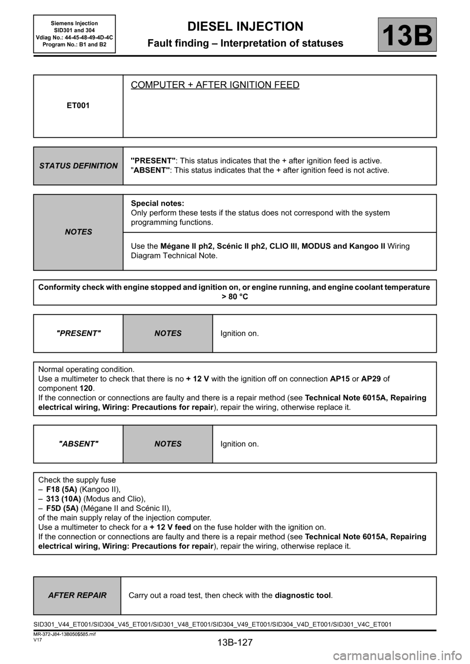
ET001
COMPUTER + AFTER IGNITION FEED
STATUS DEFINITION"PRESENT": This status indicates that the + after ignition feed is active.
"ABSENT": This status indicates that the + after ignition feed is not active.
NOTESSpecial notes:
Only perform these tests if the status does not correspond with the system
programming functions.
Use the Mégane II ph2, Scénic II ph2, CLIO III, MODUS and Kangoo II Wiring
Diagram Technical Note.
Conformity check with engine stopped and ignition on, or engine running, and engine coolant temperature
>80 °C
"PRESENT"
NOTESIgnition on.
Normal operating condition.
Use a multimeter to check that there is no +12V with the ignition off on connectionAP15 or AP29 of
component120.
If the connection or connections are faulty and there is a repair method (see Technical Note 6015A, Repairing
electrical wiring, Wiring: Precautions for repair), repair the wiring, otherwise replace it.
"ABSENT"
NOTESIgnition on.
Check the supply fuse
–F18 (5A) (Kangoo II),
–313 (10A) (Modus and Clio),
–F5D (5A) (Mégane II and Scénic II),
of the main supply relay of the injection computer.
Use a multimeter to check for a + 12 V feed on the fuse holder with the ignition on.
If the connection or connections are faulty and there is a repair method (see Technical Note 6015A, Repairing
electrical wiring, Wiring: Precautions for repair), repair the wiring, otherwise replace it.
AFTER REPAIRCarry out a road test, then check with the diagnostic tool.
SID301_V44_ET001/SID304_V45_ET001/SID301_V48_ET001/SID304_V49_ET001/SID304_V4D_ET001/SID301_V4C_ET001
MR-372-J84-13B050$585.mif
Siemens Injection
SID301 and 304
Vdiag No.: 44-45-48-49-4D-4C
Program No.: B1 and B2
Page 128 of 329
13B-128
MR-372-J84-13B050$585.mif
V17
DIESEL INJECTION
Fault finding – Interpretation of statuses
Siemens Injection
SID301 and 304
Vdiag No.: 44-45-48-49-4D-4C
Program No.: B1 and B2
13B
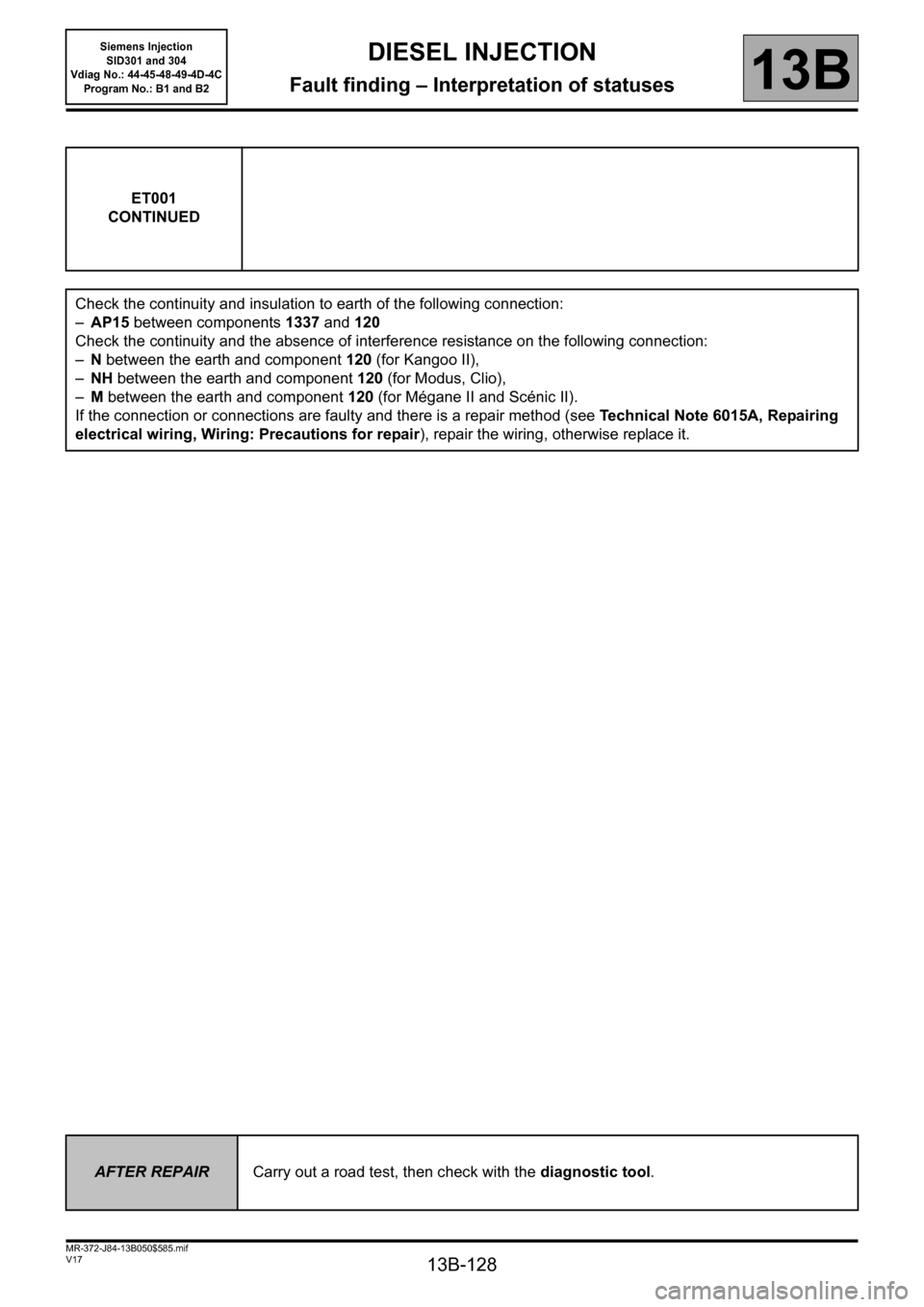
ET001
CONTINUED
Check the continuity and insulation to earth of the following connection:
–AP15 between components1337 and 120
Check the continuity and the absence of interference resistance on the following connection:
–N between the earth and component120 (for Kangoo II),
–NH between the earth and component120 (for Modus, Clio),
–M between the earth and component120 (for Mégane II and Scénic II).
If the connection or connections are faulty and there is a repair method (see Technical Note 6015A, Repairing
electrical wiring, Wiring: Precautions for repair), repair the wiring, otherwise replace it.
AFTER REPAIRCarry out a road test, then check with the diagnostic tool.
Page 140 of 329
13B-140
MR-372-J84-13B050$585.mif
V17
Siemens Injection
SID301 and 304
Vdiag No.: 44-45-48-49-4D-4C
Program No.: B1 and B2DIESEL INJECTION
Fault finding – Interpretation of statuses13B
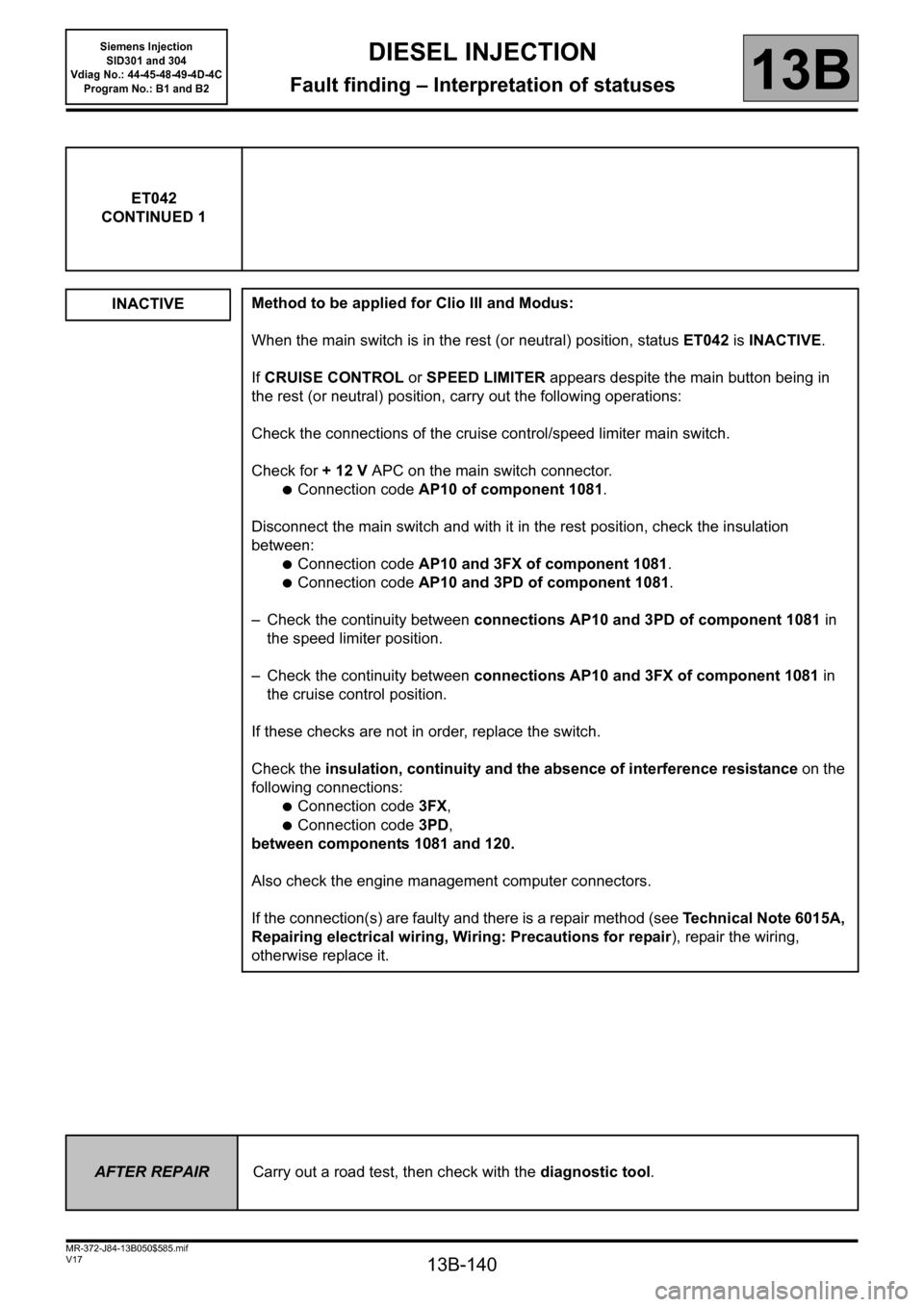
ET042
CONTINUED 1
INACTIVE
Method to be applied for Clio III and Modus:
When the main switch is in the rest (or neutral) position, status ET042 is INACTIVE.
If CRUISE CONTROL or SPEED LIMITER appears despite the main button being in
the rest (or neutral) position, carry out the following operations:
Check the connections of the cruise control/speed limiter main switch.
Check for + 12 V APC on the main switch connector.
●Connection code AP10 of component 1081.
Disconnect the main switch and with it in the rest position, check the insulation
between:
●Connection code AP10 and 3FX of component 1081.
●Connection code AP10 and 3PD of component 1081.
– Check the continuity between connections AP10 and 3PD of component 1081 in
the speed limiter position.
– Check the continuity between connections AP10 and 3FX of component 1081 in
the cruise control position.
If these checks are not in order, replace the switch.
Check the insulation, continuity and the absence of interference resistance on the
following connections:
●Connection code 3FX,
●Connection code 3PD,
between components 1081 and 120.
Also check the engine management computer connectors.
If the connection(s) are faulty and there is a repair method (see Technical Note 6015A,
Repairing electrical wiring, Wiring: Precautions for repair), repair the wiring,
otherwise replace it.
AFTER REPAIRCarry out a road test, then check with the diagnostic tool.
Page 141 of 329
13B-141
MR-372-J84-13B050$585.mif
V17
Siemens Injection
SID301 and 304
Vdiag No.: 44-45-48-49-4D-4C
Program No.: B1 and B2DIESEL INJECTION
Fault finding – Interpretation of statuses13B
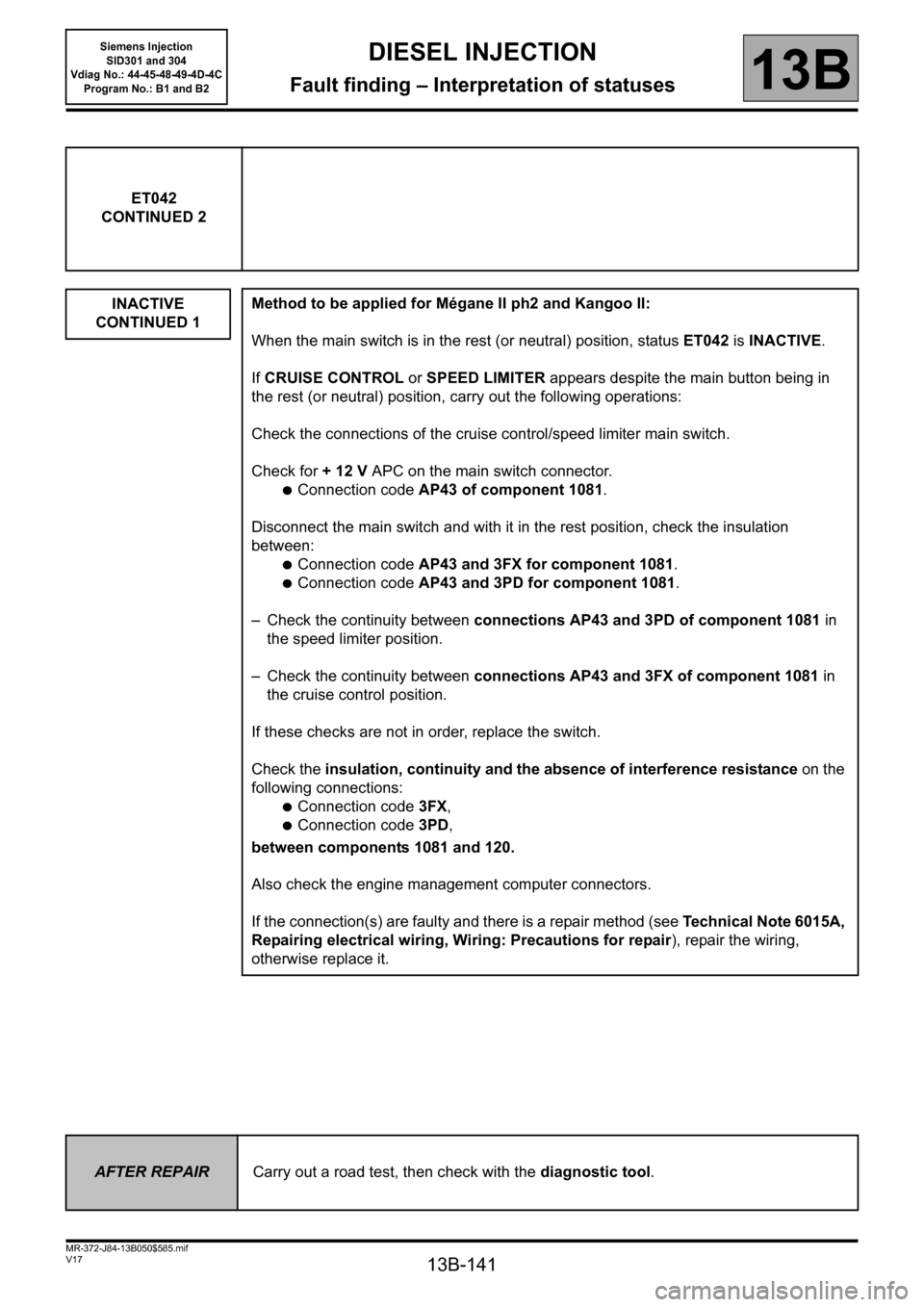
ET042
CONTINUED 2
INACTIVE
CONTINUED 1
Method to be applied for Mégane II ph2 and Kangoo II:
When the main switch is in the rest (or neutral) position, status ET042 is INACTIVE.
If CRUISE CONTROL or SPEED LIMITER appears despite the main button being in
the rest (or neutral) position, carry out the following operations:
Check the connections of the cruise control/speed limiter main switch.
Check for + 12 V APC on the main switch connector.
●Connection code AP43 of component 1081.
Disconnect the main switch and with it in the rest position, check the insulation
between:
●Connection code AP43 and 3FX for component 1081.
●Connection code AP43 and 3PD for component 1081.
– Check the continuity between connections AP43 and 3PD of component 1081 in
the speed limiter position.
– Check the continuity between connections AP43 and 3FX of component 1081 in
the cruise control position.
If these checks are not in order, replace the switch.
Check the insulation, continuity and the absence of interference resistance on the
following connections:
●Connection code 3FX,
●Connection code 3PD,
between components 1081 and 120.
Also check the engine management computer connectors.
If the connection(s) are faulty and there is a repair method (see Technical Note 6015A,
Repairing electrical wiring, Wiring: Precautions for repair), repair the wiring,
otherwise replace it.
AFTER REPAIRCarry out a road test, then check with the diagnostic tool.
Page 142 of 329
13B-142
MR-372-J84-13B050$585.mif
V17
Siemens Injection
SID301 and 304
Vdiag No.: 44-45-48-49-4D-4C
Program No.: B1 and B2DIESEL INJECTION
Fault finding – Interpretation of statuses13B
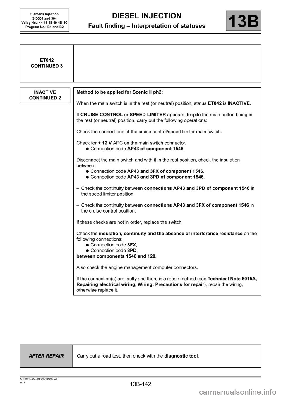
ET042
CONTINUED 3
INACTIVE
CONTINUED 2
Method to be applied for Scenic II ph2:
When the main switch is in the rest (or neutral) position, status ET042 is INACTIVE.
If CRUISE CONTROL or SPEED LIMITER appears despite the main button being in
the rest (or neutral) position, carry out the following operations:
Check the connections of the cruise control/speed limiter main switch.
Check for + 12 V APC on the main switch connector.
●Connection code AP43 of component 1546.
Disconnect the main switch and with it in the rest position, check the insulation
between:
●Connection code AP43 and 3FX of component 1546.
●Connection code AP43 and 3PD of component 1546.
– Check the continuity between connections AP43 and 3PD of component 1546 in
the speed limiter position.
– Check the continuity between connections AP43 and 3FX of component 1546 in
the cruise control position.
If these checks are not in order, replace the switch.
Check the insulation, continuity and the absence of interference resistance on the
following connections:
●Connection code 3FX,
●Connection code 3PD,
between components 1546 and 120.
Also check the engine management computer connectors.
If the connection(s) are faulty and there is a repair method (see Technical Note 6015A,
Repairing electrical wiring, Wiring: Precautions for repair), repair the wiring,
otherwise replace it.
AFTER REPAIRCarry out a road test, then check with the diagnostic tool.
Page 143 of 329
13B-143
MR-372-J84-13B050$585.mif
V17
Siemens Injection
SID301 and 304
Vdiag No.: 44-45-48-49-4D-4C
Program No.: B1 and B2DIESEL INJECTION
Fault finding – Interpretation of statuses13B
ET042
CONTINUED 4
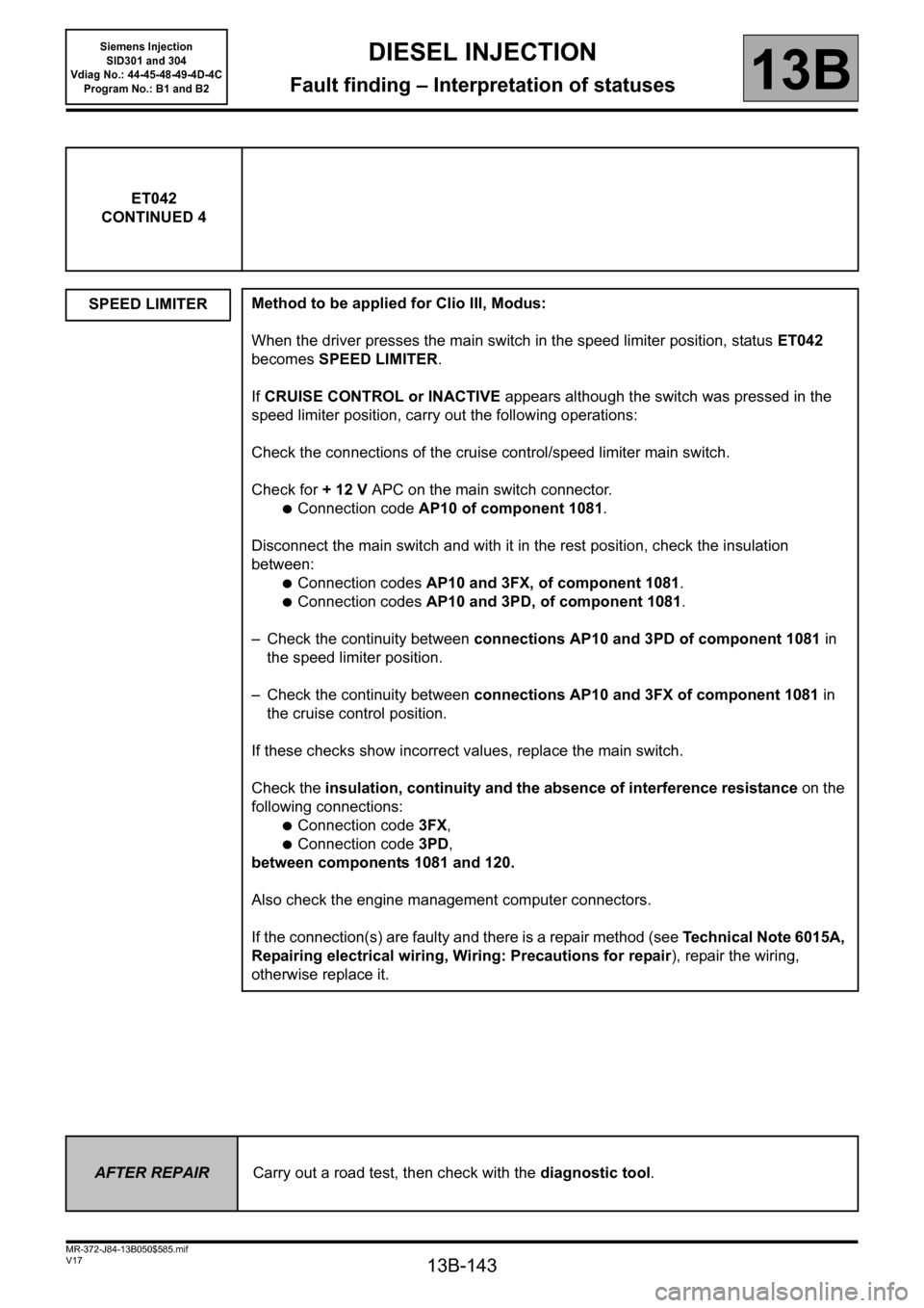
SPEED LIMITER
Method to be applied for Clio III, Modus:
When the driver presses the main switch in the speed limiter position, status ET042
becomes SPEED LIMITER.
If CRUISE CONTROL or INACTIVE appears although the switch was pressed in the
speed limiter position, carry out the following operations:
Check the connections of the cruise control/speed limiter main switch.
Check for + 12 V APC on the main switch connector.
●Connection code AP10 of component 1081.
Disconnect the main switch and with it in the rest position, check the insulation
between:
●Connection codes AP10 and 3FX, of component 1081.
●Connection codes AP10 and 3PD, of component 1081.
– Check the continuity between connections AP10 and 3PD of component 1081 in
the speed limiter position.
– Check the continuity between connections AP10 and 3FX of component 1081 in
the cruise control position.
If these checks show incorrect values, replace the main switch.
Check the insulation, continuity and the absence of interference resistance on the
following connections:
●Connection code 3FX,
●Connection code 3PD,
between components 1081 and 120.
Also check the engine management computer connectors.
If the connection(s) are faulty and there is a repair method (see Technical Note 6015A,
Repairing electrical wiring, Wiring: Precautions for repair), repair the wiring,
otherwise replace it.
AFTER REPAIRCarry out a road test, then check with the diagnostic tool.