ignition RENAULT SCENIC 2011 J95 / 3.G Engine And Peripherals Owner's Manual
[x] Cancel search | Manufacturer: RENAULT, Model Year: 2011, Model line: SCENIC, Model: RENAULT SCENIC 2011 J95 / 3.GPages: 198, PDF Size: 0.85 MB
Page 56 of 198
13B-56
AFTER REPAIRDeal with any faults displayed by the diagnostic tool. Clear the computer fault memory.
Carry out a road test followed by another check with the diagnostic tool.
V4 MR-372-J84-13B000$061.mif
DIESEL INJECTION
Fault finding – Interpretation of faults13B
DDCR INJECTION
Vdiag No.: 44, 48
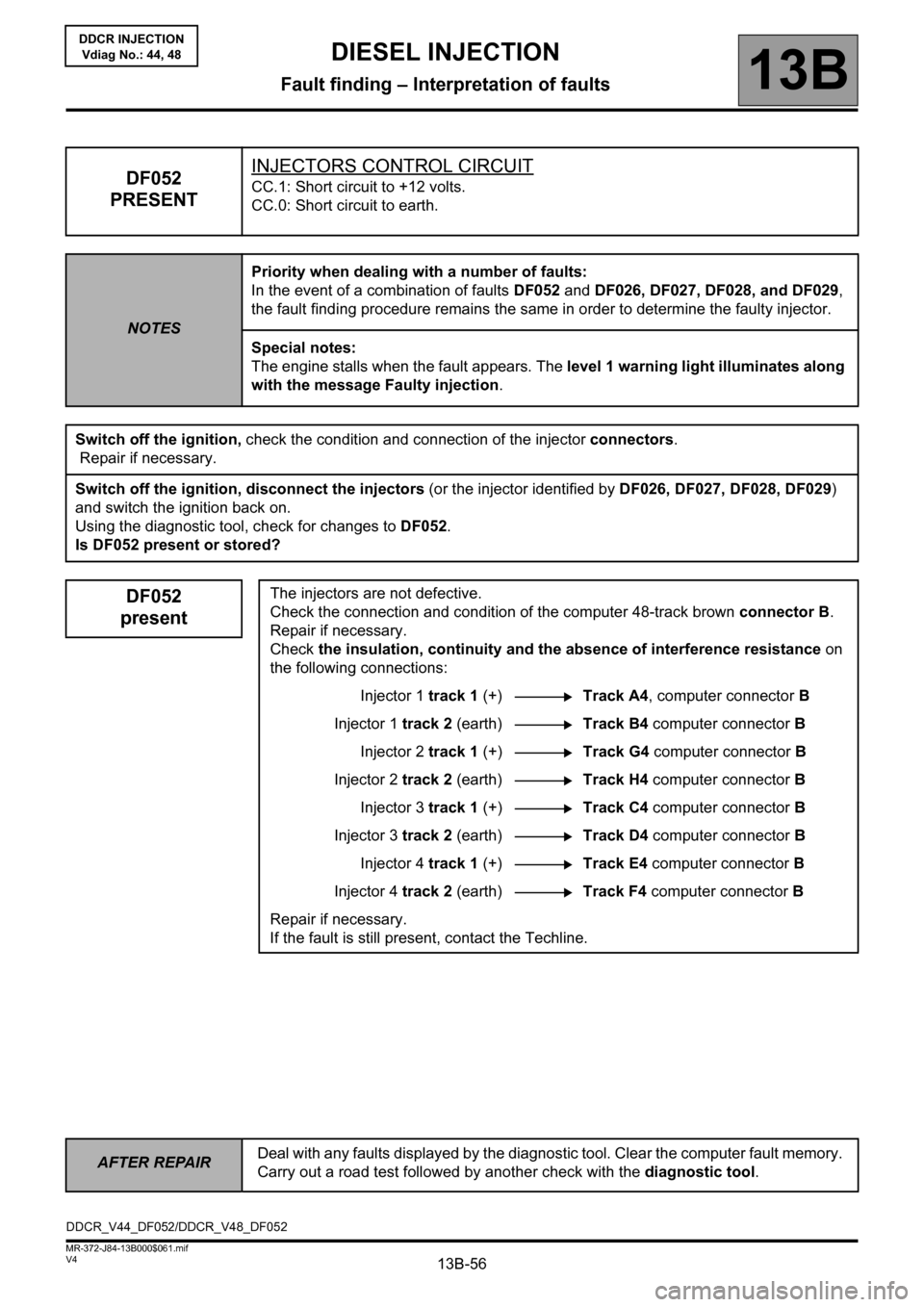
DF052
PRESENTINJECTORS CONTROL CIRCUITCC.1: Short circuit to +12 volts.
CC.0: Short circuit to earth.
NOTESPriority when dealing with a number of faults:
In the event of a combination of faults DF052 and DF026, DF027, DF028, and DF029,
the fault finding procedure remains the same in order to determine the faulty injector.
Special notes:
The engine stalls when the fault appears. The level 1 warning light illuminates along
with the message Faulty injection.
Switch off the ignition, check the condition and connection of the injector connectors.
Repair if necessary.
Switch off the ignition, disconnect the injectors (or the injector identified by DF026, DF027, DF028, DF029)
and switch the ignition back on.
Using the diagnostic tool, check for changes to DF052.
Is DF052 present or stored?
DF052
presentThe injectors are not defective.
Check the connection and condition of the computer 48-track brown connector B.
Repair if necessary.
Check the insulation, continuity and the absence of interference resistance on
the following connections:
Injector 1 track 1 (+)Track A4, computer connector B
Injector 1 track 2 (earth)Track B4 computer connector B
Injector 2 track 1 (+)Track G4 computer connector B
Injector 2 track 2 (earth)Track H4 computer connector B
Injector 3 track 1 (+)Track C4 computer connector B
Injector 3 track 2 (earth)Track D4 computer connector B
Injector 4 track 1 (+)Track E4 computer connector B
Injector 4 track 2 (earth)Track F4 computer connector B
Repair if necessary.
If the fault is still present, contact the Techline.
DDCR_V44_DF052/DDCR_V48_DF052
Page 57 of 198
13B-57
AFTER REPAIRDeal with any faults displayed by the diagnostic tool. Clear the computer fault memory.
Carry out a road test followed by another check with the diagnostic tool.
V4 MR-372-J84-13B000$061.mif
DIESEL INJECTION
Fault finding – Interpretation of faults13B
DDCR INJECTION
Vdiag No.: 44, 48
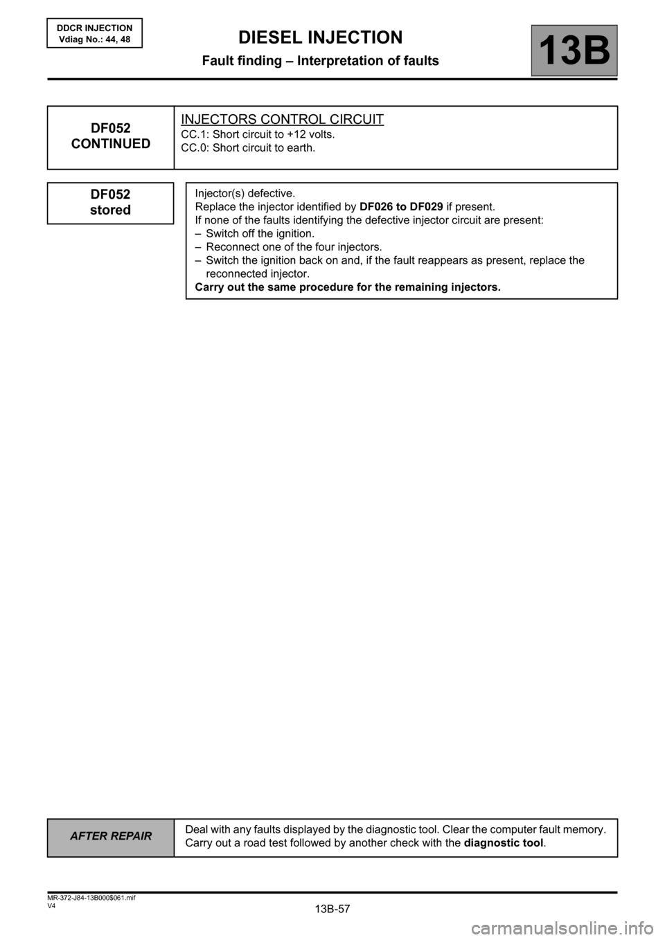
DF052
CONTINUEDINJECTORS CONTROL CIRCUITCC.1: Short circuit to +12 volts.
CC.0: Short circuit to earth.
DF052
storedInjector(s) defective.
Replace the injector identified by DF026 to DF029 if present.
If none of the faults identifying the defective injector circuit are present:
– Switch off the ignition.
– Reconnect one of the four injectors.
– Switch the ignition back on and, if the fault reappears as present, replace the
reconnected injector.
Carry out the same procedure for the remaining injectors.
Page 60 of 198
13B-60
AFTER REPAIRDeal with any faults declared by the diagnostic tool. Clear the computer fault memory.
Carry out a road test followed by another check with the diagnostic tool.
V4 MR-372-J84-13B000$062.mif
DIESEL INJECTION
Fault finding – Interpretation of faults13B
DDCR INJECTION
Vdiag No.: 44, 48
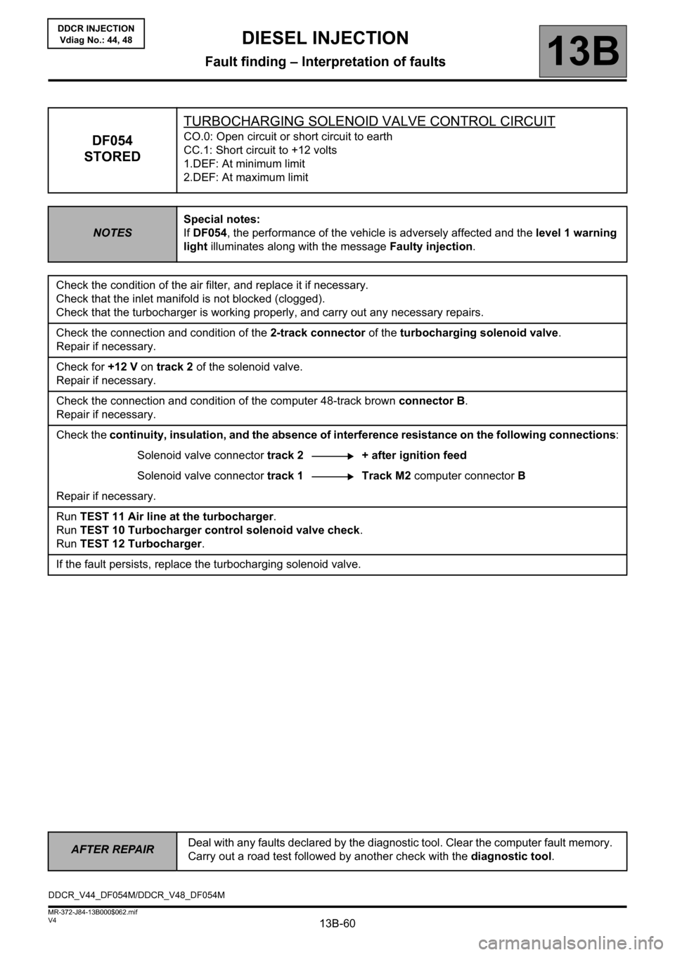
DF054
STOREDTURBOCHARGING SOLENOID VALVE CONTROL CIRCUITCO.0: Open circuit or short circuit to earth
CC.1: Short circuit to +12 volts
1.DEF: At minimum limit
2.DEF: At maximum limit
NOTESSpecial notes:
If DF054, the performance of the vehicle is adversely affected and the level 1 warning
light illuminates along with the message Faulty injection.
Check the condition of the air filter, and replace it if necessary.
Check that the inlet manifold is not blocked (clogged).
Check that the turbocharger is working properly, and carry out any necessary repairs.
Check the connection and condition of the 2-track connector of the turbocharging solenoid valve.
Repair if necessary.
Check for +12 V on track 2 of the solenoid valve.
Repair if necessary.
Check the connection and condition of the computer 48-track brown connector B.
Repair if necessary.
Check the continuity, insulation, and the absence of interference resistance on the following connections:
Solenoid valve connector track 2 + after ignition feed
Solenoid valve connector track 1 Track M2 computer connector B
Repair if necessary.
Run TEST 11 Air line at the turbocharger.
Run TEST 10 Turbocharger control solenoid valve check.
Run TEST 12 Turbocharger.
If the fault persists, replace the turbocharging solenoid valve.
DDCR_V44_DF054M/DDCR_V48_DF054M
Page 61 of 198
13B-61
AFTER REPAIRDeal with any faults declared by the diagnostic tool. Clear the computer fault memory.
Carry out a road test followed by another check with the diagnostic tool.
V4 MR-372-J84-13B000$062.mif
DIESEL INJECTION
Fault finding – Interpretation of faults13B
DDCR INJECTION
Vdiag No.: 44, 48
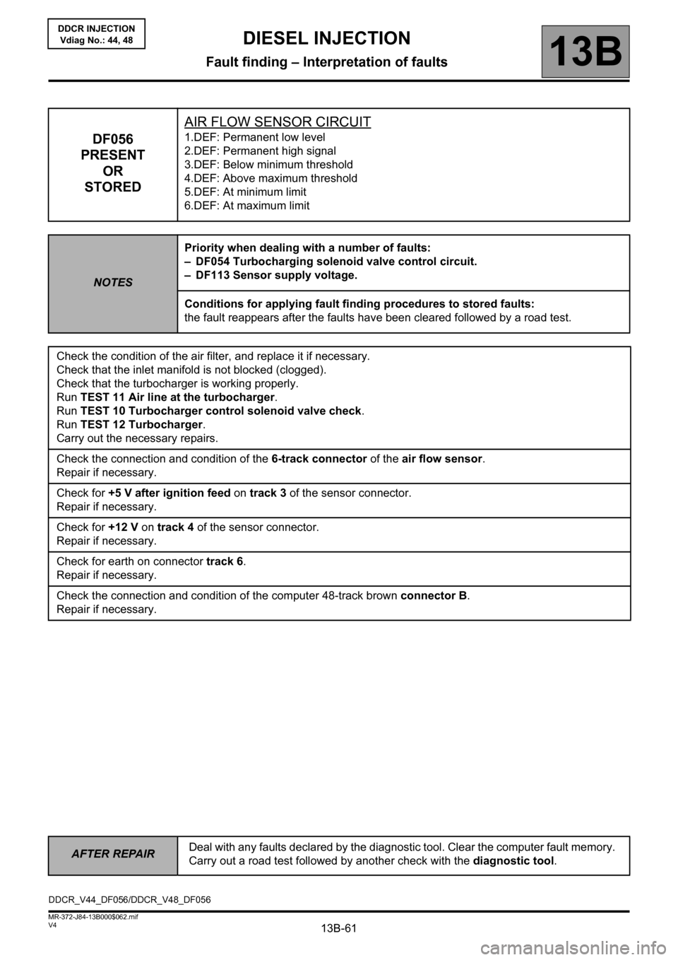
DF056
PRESENT
OR
STOREDAIR FLOW SENSOR CIRCUIT1.DEF: Permanent low level
2.DEF: Permanent high signal
3.DEF: Below minimum threshold
4.DEF: Above maximum threshold
5.DEF: At minimum limit
6.DEF: At maximum limit
NOTESPriority when dealing with a number of faults:
– DF054 Turbocharging solenoid valve control circuit.
– DF113 Sensor supply voltage.
Conditions for applying fault finding procedures to stored faults:
the fault reappears after the faults have been cleared followed by a road test.
Check the condition of the air filter, and replace it if necessary.
Check that the inlet manifold is not blocked (clogged).
Check that the turbocharger is working properly.
Run TEST 11 Air line at the turbocharger.
Run TEST 10 Turbocharger control solenoid valve check.
Run TEST 12 Turbocharger.
Carry out the necessary repairs.
Check the connection and condition of the 6-track connector of the air flow sensor.
Repair if necessary.
Check for +5 V after ignition feed on track 3 of the sensor connector.
Repair if necessary.
Check for +12 V on track 4 of the sensor connector.
Repair if necessary.
Check for earth on connector track 6.
Repair if necessary.
Check the connection and condition of the computer 48-track brown connector B.
Repair if necessary.
DDCR_V44_DF056/DDCR_V48_DF056
Page 62 of 198
13B-62
AFTER REPAIRDeal with any faults declared by the diagnostic tool. Clear the computer fault memory.
Carry out a road test followed by another check with the diagnostic tool.
V4 MR-372-J84-13B000$062.mif
DIESEL INJECTION
Fault finding – Interpretation of faults13B
DDCR INJECTION
Vdiag No.: 44, 48
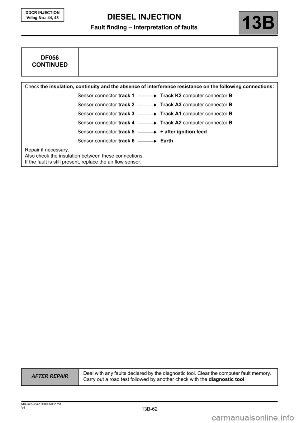
DF056
CONTINUED
Check the insulation, continuity and the absence of interference resistance on the following connections:
Sensor connector track 1 Track K2 computer connector B
Sensor connector track 2 Track A3 computer connector B
Sensor connector track 3 Track A1 computer connector B
Sensor connector track 4 Track A2 computer connector B
Sensor connector track 5 + after ignition feed
Sensor connector track 6Earth
Repair if necessary.
Also check the insulation between these connections.
If the fault is still present, replace the air flow sensor.
Page 83 of 198
13B-83V4 MR-372-J84-13B000$070.mif
13B
DDCR INJECTION
Vdiag No.: 44, 48
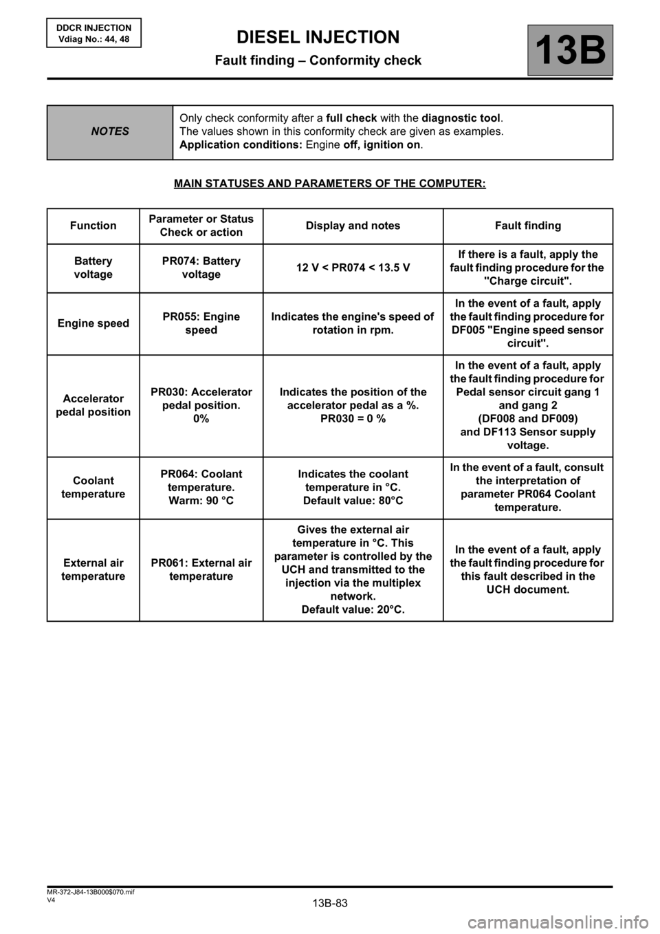
MAIN STATUSES AND PARAMETERS OF THE COMPUTER:
NOTESOnly check conformity after a full check with the diagnostic tool.
The values shown in this conformity check are given as examples.
Application conditions: Engine off, ignition on.
FunctionParameter or Status
Check or actionDisplay and notes Fault finding
Battery
voltagePR074: Battery
voltage12 V < PR074 < 13.5 VIf there is a fault, apply the
fault finding procedure for the
"Charge circuit".
Engine speedPR055: Engine
speedIndicates the engine's speed of
rotation in rpm.In the event of a fault, apply
the fault finding procedure for
DF005 "Engine speed sensor
circuit".
Accelerator
pedal positionPR030: Accelerator
pedal position.
0%Indicates the position of the
accelerator pedal as a %.
PR030 = 0 %In the event of a fault, apply
the fault finding procedure for
Pedal sensor circuit gang 1
and gang 2
(DF008 and DF009)
and DF113 Sensor supply
voltage.
Coolant
temperaturePR064: Coolant
temperature.
Warm: 90 °CIndicates the coolant
temperature in °C.
Default value: 80°CIn the event of a fault, consult
the interpretation of
parameter PR064 Coolant
temperature.
External air
temperaturePR061: External air
temperatureGives the external air
temperature in °C. This
parameter is controlled by the
UCH and transmitted to the
injection via the multiplex
network.
Default value: 20°C.In the event of a fault, apply
the fault finding procedure for
this fault described in the
UCH document.
DIESEL INJECTION
Fault finding – Conformity check
Page 84 of 198
13B-84V4 MR-372-J84-13B000$070.mif
DIESEL INJECTION
Fault finding – Conformity check13B
DDCR INJECTION
Vdiag No.: 44, 48
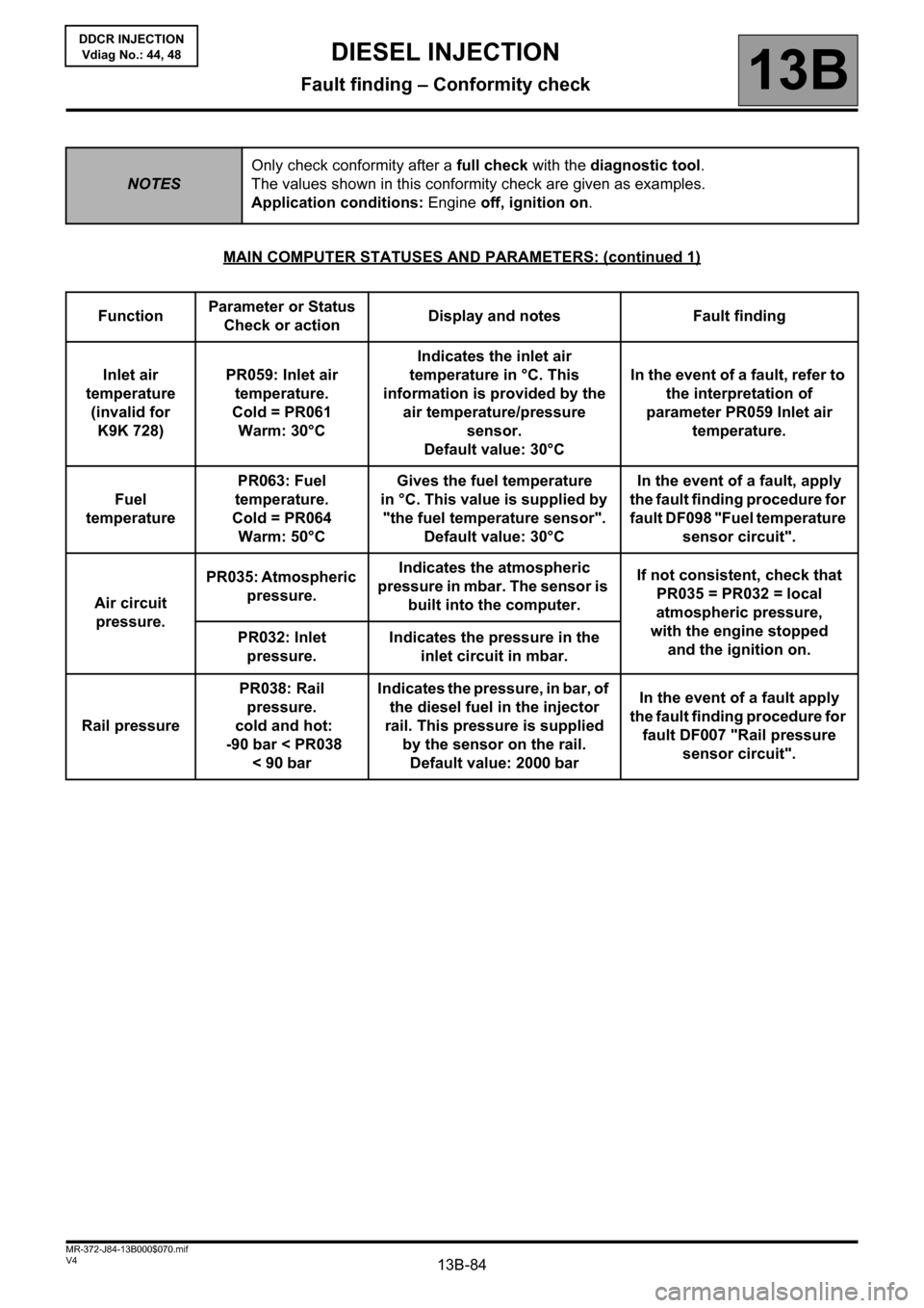
MAIN COMPUTER STATUSES AND PARAMETERS: (continued 1)
NOTESOnly check conformity after a full check with the diagnostic tool.
The values shown in this conformity check are given as examples.
Application conditions: Engine off, ignition on.
FunctionParameter or Status
Check or actionDisplay and notes Fault finding
Inlet air
temperature
(invalid for
K9K 728)PR059: Inlet air
temperature.
Cold = PR061
Warm: 30°CIndicates the inlet air
temperature in °C. This
information is provided by the
air temperature/pressure
sensor.
Default value: 30°CIn the event of a fault, refer to
the interpretation of
parameter PR059 Inlet air
temperature.
Fuel
temperaturePR063: Fuel
temperature.
Cold = PR064
Warm: 50°CGives the fuel temperature
in °C. This value is supplied by
"the fuel temperature sensor".
Default value: 30°CIn the event of a fault, apply
the fault finding procedure for
fault DF098 "Fuel temperature
sensor circuit".
Air circuit
pressure.PR035: Atmospheric
pressure.Indicates the atmospheric
pressure in mbar. The sensor is
built into the computer.If not consistent, check that
PR035 = PR032 = local
atmospheric pressure,
with the engine stopped
and the ignition on. PR032: Inlet
pressure.Indicates the pressure in the
inlet circuit in mbar.
Rail pressurePR038: Rail
pressure.
cold and hot:
-90 bar < PR038
<90barIndicates the pressure, in bar, of
the diesel fuel in the injector
rail. This pressure is supplied
by the sensor on the rail.
Default value: 2000 barIn the event of a fault apply
the fault finding procedure for
fault DF007 "Rail pressure
sensor circuit".
Page 85 of 198

13B-85V4 MR-372-J84-13B000$070.mif
DIESEL INJECTION
Fault finding – Conformity check13B
DDCR INJECTION
Vdiag No.: 44, 48
MAIN COMPUTER STATUSES AND PARAMETERS: (continued 2)
NOTESOnly check conformity after a full check with the diagnostic tool.
The values shown in this conformity check are given as examples.
Application conditions: Engine off, ignition on.
FunctionParameter or Status
Check or actionDisplay and notes Fault finding
EngineET038: Engine.
UNDER + AFTER
IGNITION FEEDIndicates the current status of
the engine.
- UNDER + AFTER IGNITION
FEED
- UNDER STARTER
- RUNNING
- SUPPLY MAINTAINED: Supply
maintained during the power
latch phase.
- STALLED: When the engine
has stalled.
- PROTECTED: When a level 2
fault has appeared or when
the engine speed is locked at
a certain value.NONE
Engine
immobiliserET003: Engine
immobiliser.
INACTIVEIndicates the status of the
immobiliser system.
- INACTIVE: The injection
computer has recognised the
immobiliser code transmitted
by the UCH.
- ACTIVE: The injection
computer does not recognise
the immobiliser code
transmitted by the UCH.If ACTIVE, apply the
associated Help given in
the tool.
Code
programmedET006: Code
programmed
YESIndicates whether the
immobiliser code has been
programmed into the computer.
- YES: Code is programmed.
- NO: Code was not
programmed into the injection
computer.If NO, contact the Techline.
Page 86 of 198
13B-86V4 MR-372-J84-13B000$070.mif
DIESEL INJECTION
Fault finding – Conformity check13B
DDCR INJECTION
Vdiag No.: 44, 48
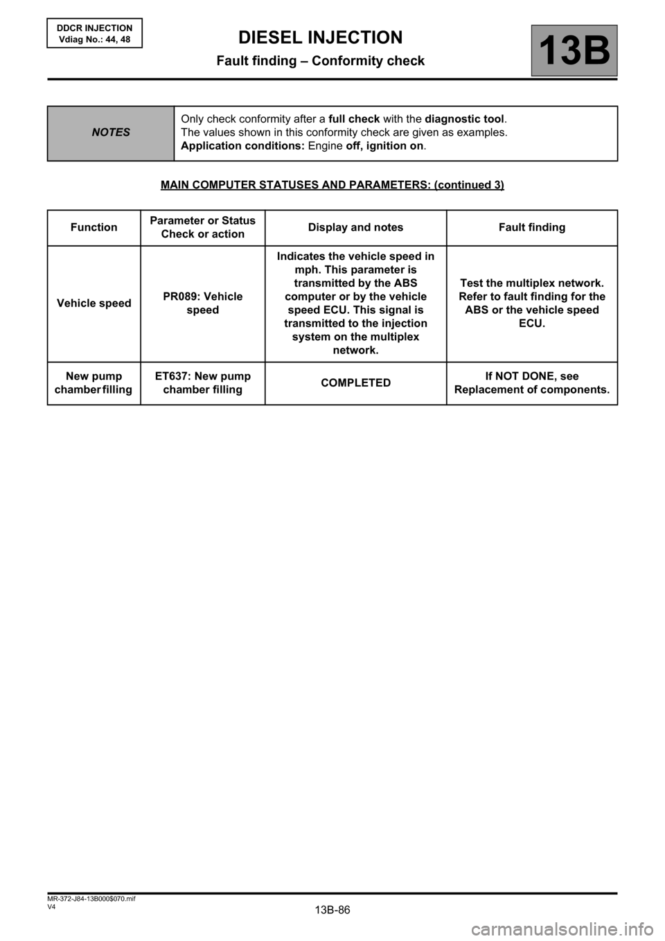
MAIN COMPUTER STATUSES AND PARAMETERS: (continued 3)
NOTESOnly check conformity after a full check with the diagnostic tool.
The values shown in this conformity check are given as examples.
Application conditions: Engine off, ignition on.
FunctionParameter or Status
Check or actionDisplay and notes Fault finding
Vehicle speedPR089: Vehicle
speedIndicates the vehicle speed in
mph. This parameter is
transmitted by the ABS
computer or by the vehicle
speed ECU. This signal is
transmitted to the injection
system on the multiplex
network. Test the multiplex network.
Refer to fault finding for the
ABS or the vehicle speed
ECU.
New pump
chamber filling ET637: New pump
chamber fillingCOMPLETEDIf NOT DONE, see
Replacement of components.
Page 87 of 198
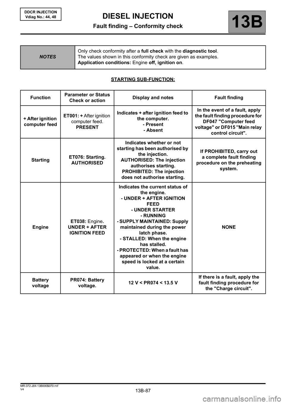
13B-87V4 MR-372-J84-13B000$070.mif
DIESEL INJECTION
Fault finding – Conformity check13B
DDCR INJECTION
Vdiag No.: 44, 48
STARTING SUB-FUNCTION:
NOTESOnly check conformity after a full check with the diagnostic tool.
The values shown in this conformity check are given as examples.
Application conditions: Engine off, ignition on.
FunctionParameter or Status
Check or actionDisplay and notes Fault finding
+ After ignition
computer feedET001: + After ignition
computer feed.
PRESENTIndicates + after ignition feed to
the computer.
- Present
- AbsentIn the event of a fault, apply
the fault finding procedure for
DF047 "Computer feed
voltage" or DF015 "Main relay
control circuit".
StartingET076: Starting.
AUTHORISEDIndicates whether or not
starting has been authorised by
the injection.
AUTHORISED: The injection
authorises starting.
PROHIBITED: The injection
does not authorise starting.If PROHIBITED, carry out
a complete fault finding
procedure on the preheating
system.
EngineET038: Engine.
UNDER + AFTER
IGNITION FEEDIndicates the current status of
the engine.
- UNDER + AFTER IGNITION
FEED
- UNDER STARTER
- RUNNING
- SUPPLY MAINTAINED: Supply
maintained during the power
latch phase.
- STALLED: When the engine
has stalled.
- PROTECTED: When a fault has
appeared or when the engine
speed is locked at a certain
value.NONE
Battery
voltagePR074: Battery
voltage.12 V < PR074 < 13.5 VIf there is a fault, apply the
fault finding procedure for
the "Charge circuit".