ESP RENAULT SCENIC 2011 J95 / 3.G Engine And Peripherals Workshop Manual
[x] Cancel search | Manufacturer: RENAULT, Model Year: 2011, Model line: SCENIC, Model: RENAULT SCENIC 2011 J95 / 3.GPages: 198, PDF Size: 0.85 MB
Page 3 of 198

13B-3V4 MR-372-J84-13B000$010.mif
DIESEL INJECTION
Fault finding – Introduction13B
DDCR INJECTION
Vdiag No.: 44, 48
To cut off + after ignition, proceed as follows:
– disconnect the diagnostic tool,
– press the start button twice briefly (less than 3 seconds),
– check that the + after ignition feed has been cut off by checking that the computer warning lights on the instrument
panel have gone out.
Fault
Faults are declared present or stored (depending on whether they appeared in a certain context and have
disappeared since, or whether they remain present but are not diagnosed within the current context).
The present or stored status of the faults should be taken into consideration when the diagnostic tool is used after
the + after ignition feed has been connected (with no system components activated).
For a present fault,apply the procedure described in the Interpretation of faults section.
For a stored fault, note the faults displayed and apply the Notes paragraph.
If the fault is confirmed when the notes are applied, the fault is present. Deal with the fault.
If the fault is not confirmed, check:
– the electrical lines which correspond to the fault,
– the connectors on these lines (corrosion, bent pins, etc.),
– the resistance of the faulty component,
– the condition of the wires (melted or cut insulation, wear).
Or use diagnostics to check the circuit of the suspect component.
Conformity check
The conformity check is designed to check the statuses and parameters that do not display any faults on
the diagnostic tool when inconsistent. Therefore, this stage is used to:
Run fault finding on faults that do not have a fault display, and which may correspond to a customer complaint,
– Check that the system is operating correctly and that there is no risk of a fault recurring after repair.
– This section features the fault finding procedures for statuses and parameters, and the conditions for checking
them.
If a status is not operating normally or a parameter is outside permitted tolerance values, you should consult
the corresponding fault finding page.
Customer complaints - Fault-finding chart
If the diagnostic tool check is correct, but the customer complaint is still present, it should be dealt with using
Customer complaints.NOTE:
The right-hand and left-hand xenon bulb computers are powered when the dipped headlights are lit. Fault finding
can only be carried out on them after the ignition has been switched on in fault finding mode (forced + after ignition
feed) and the dipped headlights are on.
A summary of the overall procedure to follow is provided on the following page in the form of a flow chart.
Page 5 of 198
13B-5V4 MR-372-J84-13B000$010.mif
DIESEL INJECTION
Fault finding – Introduction13B
DDCR INJECTION
Vdiag No.: 44, 48
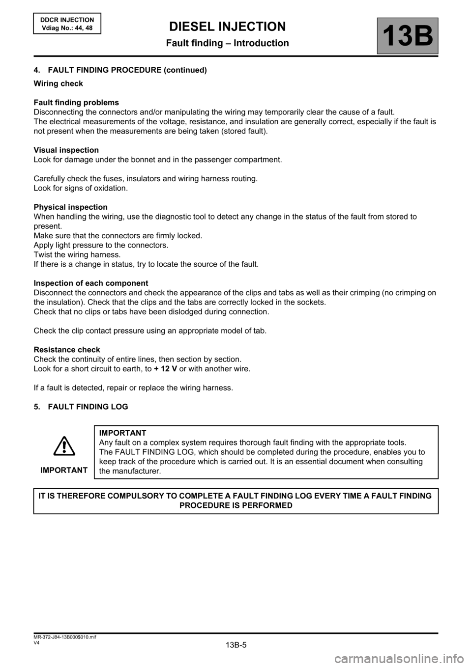
4. FAULT FINDING PROCEDURE (continued)
Wiring check
Fault finding problems
Disconnecting the connectors and/or manipulating the wiring may temporarily clear the cause of a fault.
The electrical measurements of the voltage, resistance, and insulation are generally correct, especially if the fault is
not present when the measurements are being taken (stored fault).
Visual inspection
Look for damage under the bonnet and in the passenger compartment.
Carefully check the fuses, insulators and wiring harness routing.
Look for signs of oxidation.
Physical inspection
When handling the wiring, use the diagnostic tool to detect any change in the status of the fault from stored to
present.
Make sure that the connectors are firmly locked.
Apply light pressure to the connectors.
Twist the wiring harness.
If there is a change in status, try to locate the source of the fault.
Inspection of each component
Disconnect the connectors and check the appearance of the clips and tabs as well as their crimping (no crimping on
the insulation). Check that the clips and the tabs are correctly locked in the sockets.
Check that no clips or tabs have been dislodged during connection.
Check the clip contact pressure using an appropriate model of tab.
Resistance check
Check the continuity of entire lines, then section by section.
Look for a short circuit to earth, to + 12 V or with another wire.
If a fault is detected, repair or replace the wiring harness.
5. FAULT FINDING LOG
IMPORTANTIMPORTANT
Any fault on a complex system requires thorough fault finding with the appropriate tools.
The FAULT FINDING LOG, which should be completed during the procedure, enables you to
keep track of the procedure which is carried out. It is an essential document when consulting
the manufacturer.
IT IS THEREFORE COMPULSORY TO COMPLETE A FAULT FINDING LOG EVERY TIME A FAULT FINDING
PROCEDURE IS PERFORMED
Page 8 of 198

13B-8V4 MR-372-J84-13B000$020.mif
13B
DDCR INJECTION
Vdiag No.: 44, 48
System outline
The DDCR injection system used on the K9 engine is an electronically managed high pressure injection system.
The fuel is compressed by a high pressure pump then stored in a rail that feeds the injectors. Injection occurs when
a current pulse is applied to the injector holders. The injected flow is proportional to the rail pressure and to
the applied pulse length, and the start of injection is phased with the start of the pulse.
The circuit comprises two subsystems, which are distinguished by the fuel pressure level.
– The low pressure system includes the tank, diesel fuel filter, transfer pump and injector holder return pipes.
– The high pressure circuit contains the high pressure pump, the rail, the injector holders and the high pressure tubes.
Finally, there are a certain number of sensors and regulating actuators for controlling and monitoring the entire
system.
Functions provided
Function: Fuel supply management (timing, flow and pressure).
Quantity of fuel injected and injection timing adjustment
The injection checking parameters are the quantities to be injected and their respective timing. These are calculated
by the computer using signals from the following sensors:
• Engine speed (Crankshaft + Cam for synchronisation)
• Accelerator pedal
• Turbocharging pressure and air temperature (Turbocharger pressure)
• Coolant temperature
• Air temperature
• Air load (Flow and Pressure)
• Rail pressure
• Flowmeter
• Turbocharging solenoid valve
The quantities to be injected and their respective timing are converted into:
• a reference tooth
• the time between this tooth and the start of the pulse
• the time for which the supply to the injector holder is on
An electrical current (pulse) is sent to each injector holder according to previously calculated data. The system
makes one or two injections (1 pilot injection, 1 main injection). The general principle is to calculate an overall
injected flow which will then be divided into a main injection flow and a pilot injection flow, to help the combustion
process work properly and to reduce pollutant emissions.
An accelerometer is used to monitor some of the fuel injection deviation. This has several roles:
• Protecting the engine by detecting injection leaks (disabled on the basic vehicle).
• Checking the pilot quantity by measuring deviation and dispersion
• By changing both the duration and timing of the injection, the quantity of fuel injected and the mixture ignition timing
can be adjusted.
DIESEL INJECTION
Fault finding – System operation
Page 12 of 198

13B-12V4 MR-372-J84-13B000$020.mif
DIESEL INJECTION
Fault finding – System operation13B
DDCR INJECTION
Vdiag No.: 44, 48
Functions included
Air conditioning management assistance
For vehicles with air conditioning, the DDCR system can switch off the air conditioning under certain engine
operating conditions:
– when requested by the driver,
– when starting the engine,
– if the engine overheats (in order to reduce the power the engine has to supply),
– when the engine speed is kept at a very high level (to protect the compressor),
– during transition phases (e.g. under heavy acceleration when overtaking, anti-stalling and moving off strategies).
These conditions are only taken into account when they do not occur repeatedly, in order to prevent system
instabilities (erratic deactivations),
– when certain faults appear.
Cold loop air conditioning management
The air conditioning is the cold loop type and its management shared between several computers. The injection
computer is responsible for:
– managing demand for cold air according to the passenger compartment commands and the pressure value,
– determining the power absorbed by the compressor from the pressure,
– determining the fan unit commands according to vehicle speed and pressure.
The driver requests the air conditioning to be switched on by means of the ventilation selector coupled to a switch.
The cold air request is authorised or denied depending on the pressure measured. If this pressure is outside
the operating limits, the cold loop program is not activated.
Thermal regulation of the passenger compartment heating circuit
In a direct injection engine, fuel is injected directly into the combustion chamber. This leads to heat being lost
through the upper part of the engine and consequently, the cylinder head cooling circuit is smaller in size.
The effect of this is that the temperature of the coolant flowing through this circuit rises more slowly. However, this
coolant is also used by the passenger compartment heating system. In very cold conditions, it is therefore difficult to
achieve a comfortable passenger compartment temperature quickly.
To limit the time taken to warm up the system, air heating resistors, called RCHs, are fitted into the passenger
compartment heating circuit. The UCH decides whether the RCH are required, the UPC physically actuates
the RCH, and the injection computer determines whether to limit the power supplied to the RCH depending on
alternator charge, and also whether to disable them according to engine speed, load and vehicle speed. NOTE:
Fan unit actuation requests can be made by the injection computer, but these are sent on the CAN. These requests
depend on the air conditioning but also on the coolant temperature and vehicle speed.
Page 28 of 198
13B-28
AFTER REPAIRDeal with any faults displayed by the diagnostic tool. Clear the computer fault memory.
Carry out a road test followed by another check with the diagnostic tool.
V4 MR-372-J84-13B000$061.mif
DIESEL INJECTION
Fault finding – Interpretation of faults13B
DDCR INJECTION
Vdiag No.: 44, 48
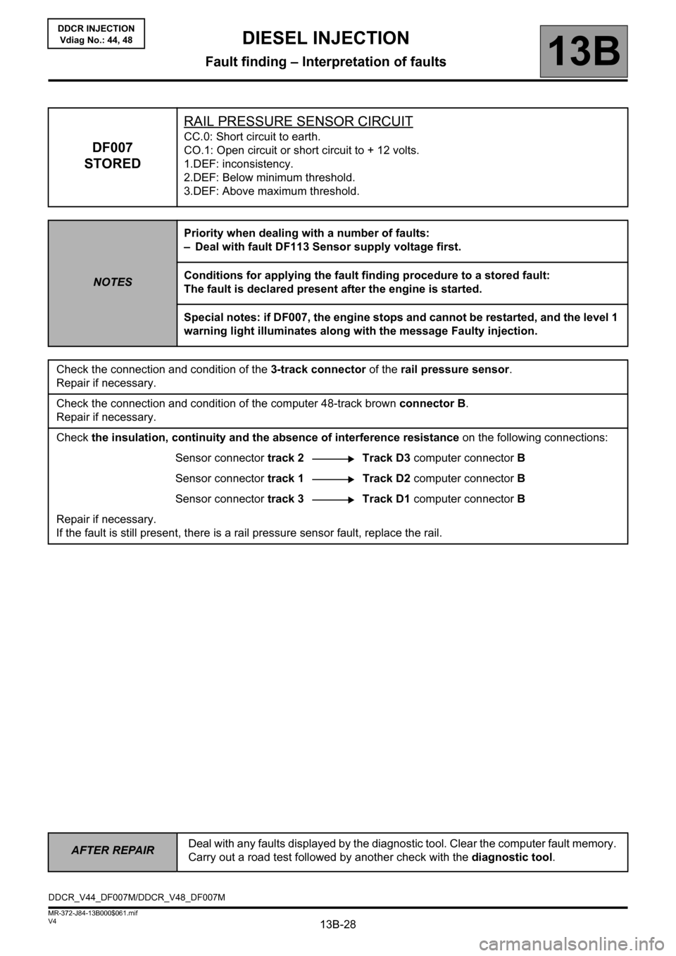
DF007
STOREDRAIL PRESSURE SENSOR CIRCUIT
CC.0: Short circuit to earth.
CO.1: Open circuit or short circuit to + 12 volts.
1.DEF: inconsistency.
2.DEF: Below minimum threshold.
3.DEF: Above maximum threshold.
NOTESPriority when dealing with a number of faults:
– Deal with fault DF113 Sensor supply voltage first.
Conditions for applying the fault finding procedure to a stored fault:
The fault is declared present after the engine is started.
Special notes: if DF007, the engine stops and cannot be restarted, and the level 1
warning light illuminates along with the message Faulty injection.
Check the connection and condition of the 3-track connector of the rail pressure sensor.
Repair if necessary.
Check the connection and condition of the computer 48-track brown connector B.
Repair if necessary.
Check the insulation, continuity and the absence of interference resistance on the following connections:
Sensor connector track 2 Track D3 computer connector B
Sensor connector track 1Track D2 computer connector B
Sensor connector track 3 Track D1 computer connector B
Repair if necessary.
If the fault is still present, there is a rail pressure sensor fault, replace the rail.
DDCR_V44_DF007M/DDCR_V48_DF007M
Page 29 of 198
13B-29
AFTER REPAIRDeal with any faults displayed by the diagnostic tool. Clear the computer fault memory.
Carry out a road test followed by another check with the diagnostic tool.
V4 MR-372-J84-13B000$061.mif
DIESEL INJECTION
Fault finding – Interpretation of faults13B
DDCR INJECTION
Vdiag No.: 44, 48
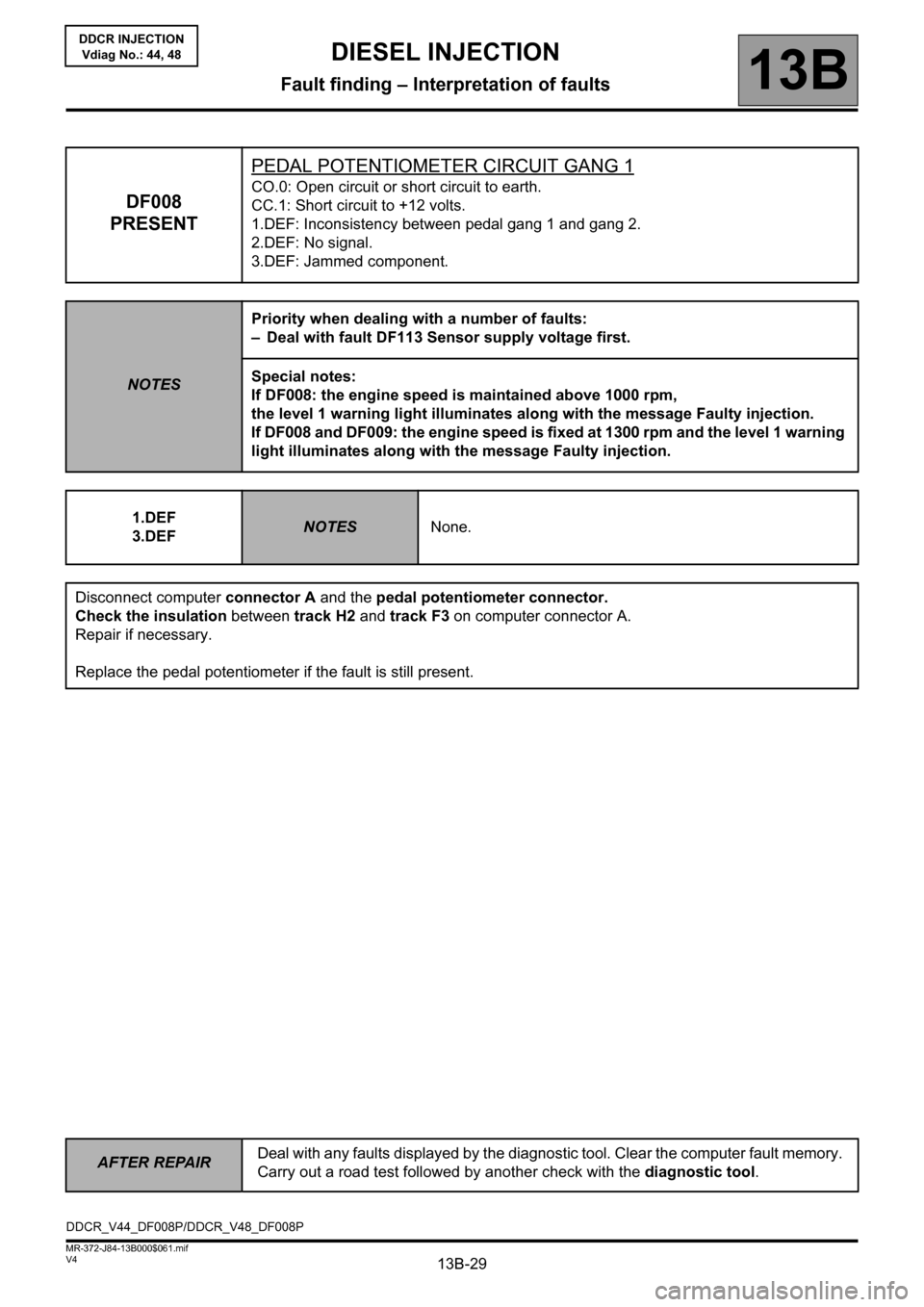
DF008
PRESENTPEDAL POTENTIOMETER CIRCUIT GANG 1
CO.0: Open circuit or short circuit to earth.
CC.1: Short circuit to +12 volts.
1.DEF: Inconsistency between pedal gang 1 and gang 2.
2.DEF: No signal.
3.DEF: Jammed component.
NOTESPriority when dealing with a number of faults:
– Deal with fault DF113 Sensor supply voltage first.
Special notes:
If DF008: the engine speed is maintained above 1000 rpm,
the level 1 warning light illuminates along with the message Faulty injection.
If DF008 and DF009: the engine speed is fixed at 1300 rpm and the level 1 warning
light illuminates along with the message Faulty injection.
1.DEF
3.DEF
NOTESNone.
Disconnect computer connector A and the pedal potentiometer connector.
Check the insulation between track H2 and track F3 on computer connector A.
Repair if necessary.
Replace the pedal potentiometer if the fault is still present.
DDCR_V44_DF008P/DDCR_V48_DF008P
Page 31 of 198
13B-31
AFTER REPAIRDeal with any faults displayed by the diagnostic tool. Clear the computer fault memory.
Carry out a road test followed by another check with the diagnostic tool.
V4 MR-372-J84-13B000$061.mif
DIESEL INJECTION
Fault finding – Interpretation of faults13B
DDCR INJECTION
Vdiag No.: 44, 48
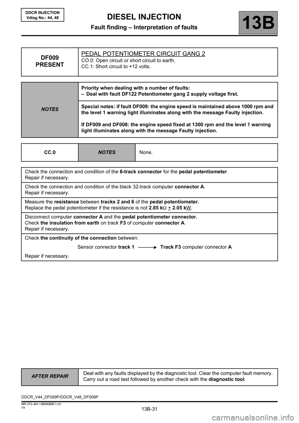
DF009
PRESENTPEDAL POTENTIOMETER CIRCUIT GANG 2CO.0: Open circuit or short circuit to earth.
CC.1: Short circuit to +12 volts.
NOTESPriority when dealing with a number of faults:
– Deal with fault DF122 Potentiometer gang 2 supply voltage first.
Special notes: if fault DF009: the engine speed is maintained above 1000 rpm and
the level 1 warning light illuminates along with the message Faulty injection.
If DF009 and DF008: the engine speed fixed at 1300 rpm and the level 1 warning
light illuminates along with the message Faulty injection.
CC.0
NOTESNone.
Check the connection and condition of the 6-track connector for the pedal potentiometer.
Repair if necessary.
Check the connection and condition of the black 32-track computer connector A.
Repair if necessary.
Measure the resistance between tracks 2 and 6 of the pedal potentiometer.
Replace the pedal potentiometer if the resistance is not 2.85 kΩ +
2.05 kW.
Disconnect computer connector A and the pedal potentiometer connector.
Check the insulation from earth on track F3 of computer connector A.
Repair if necessary.
Check the continuity of the connection between:
Sensor connector track 1 Track F3 computer connector A
Repair if necessary.
DDCR_V44_DF009P/DDCR_V48_DF009P
Page 33 of 198
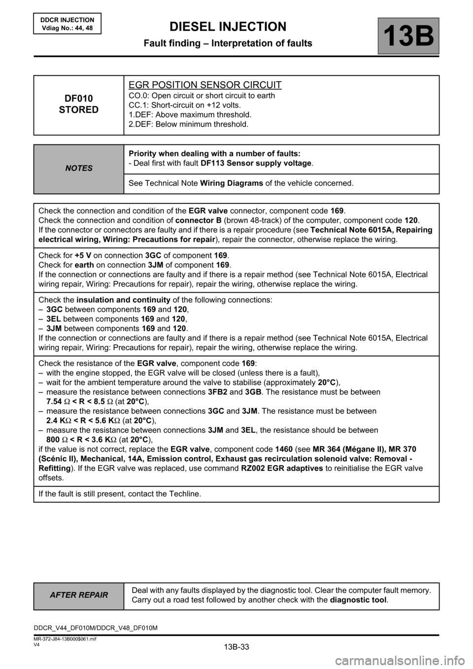
13B-33
AFTER REPAIRDeal with any faults displayed by the diagnostic tool. Clear the computer fault memory.
Carry out a road test followed by another check with the diagnostic tool.
V4 MR-372-J84-13B000$061.mif
DIESEL INJECTION
Fault finding – Interpretation of faults13B
DDCR INJECTION
Vdiag No.: 44, 48
DF010
STOREDEGR POSITION SENSOR CIRCUITCO.0: Open circuit or short circuit to earth
CC.1: Short-circuit on +12 volts.
1.DEF: Above maximum threshold.
2.DEF: Below minimum threshold.
NOTESPriority when dealing with a number of faults:
- Deal first with fault DF113 Sensor supply voltage.
See Technical Note Wiring Diagrams of the vehicle concerned.
Check the connection and condition of the EGR valve connector, component code 169.
Check the connection and condition of connector B (brown 48-track) of the computer, component code 120.
If the connector or connectors are faulty and if there is a repair procedure (see Technical Note 6015A, Repairing
electrical wiring, Wiring: Precautions for repair), repair the connector, otherwise replace the wiring.
Check for +5 V on connection 3GC of component 169.
Check for earth on connection 3JM of component 169.
If the connection or connections are faulty and if there is a repair method (see Technical Note 6015A, Electrical
wiring repair, Wiring: Precautions for repair), repair the wiring, otherwise replace the wiring.
Check the insulation and continuity of the following connections:
–3GC between components 169 and 120,
–3EL between components 169 and 120,
–3JM between components 169 and 120.
If the connection or connections are faulty and if there is a repair method (see Technical Note 6015A, Electrical
wiring repair, Wiring: Precautions for repair), repair the wiring, otherwise replace the wiring.
Check the resistance of the EGR valve, component code 169:
– with the engine stopped, the EGR valve will be closed (unless there is a fault),
– wait for the ambient temperature around the valve to stabilise (approximately 20°C),
– measure the resistance between connections 3FB2 and 3GB. The resistance must be between
7.54 Ω < R < 8.5 Ω (at 20°C),
– measure the resistance between connections 3GC and
3JM. The resistance must be between
2.4 KΩ < R < 5.6 KΩ (at 20°C),
– measure the resistance between connections 3JM and 3EL, the resistance should be between
800 Ω < R < 3.6 KΩ (at 20°C),
if the value is not correct, replace the EGR valve, component code 1460 (see MR 364 (Mégane II), MR 370
(Scénic II), Mechanical, 14A, Emission control, Exhaust gas recirculation solenoid valve: Removal -
Refitting). If the EGR valve was replaced, use command RZ002 EGR adaptives to reinitialise the EGR valve
offsets.
If the fault is still present, contact the Techline.
DDCR_V44_DF010M/DDCR_V48_DF010M
Page 51 of 198
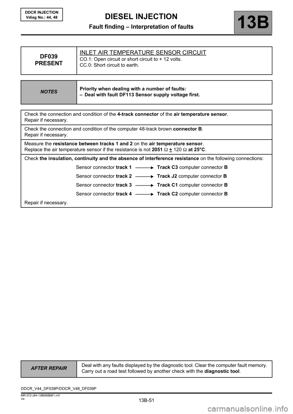
13B-51
AFTER REPAIRDeal with any faults displayed by the diagnostic tool. Clear the computer fault memory.
Carry out a road test followed by another check with the diagnostic tool.
V4 MR-372-J84-13B000$061.mif
DIESEL INJECTION
Fault finding – Interpretation of faults13B
DDCR INJECTION
Vdiag No.: 44, 48
DF039
PRESENTINLET AIR TEMPERATURE SENSOR CIRCUITCO.1: Open circuit or short circuit to + 12 volts.
CC.0: Short circuit to earth.
NOTESPriority when dealing with a number of faults:
– Deal with fault DF113 Sensor supply voltage first.
Check the connection and condition of the 4-track connector of the air temperature sensor.
Repair if necessary.
Check the connection and condition of the computer 48-track brown connector B.
Repair if necessary.
Measure the resistance between tracks 1 and 2 on the air temperature sensor.
Replace the air temperature sensor if the resistance is not 2051 Ω +
120 Ω at 25°C.
Check the insulation, continuity and the absence of interference resistance on the following connections:
Sensor connector track 1 Track C3 computer connector B
Sensor connector track 2 Track J2 computer connector B
Sensor connector track 3 Track C1 computer connector B
Sensor connector track 4 Track C2 computer connector B
Repair if necessary.
DDCR_V44_DF039P/DDCR_V48_DF039P
Page 56 of 198
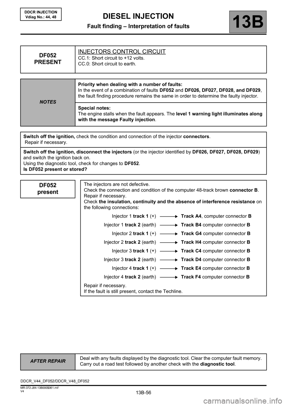
13B-56
AFTER REPAIRDeal with any faults displayed by the diagnostic tool. Clear the computer fault memory.
Carry out a road test followed by another check with the diagnostic tool.
V4 MR-372-J84-13B000$061.mif
DIESEL INJECTION
Fault finding – Interpretation of faults13B
DDCR INJECTION
Vdiag No.: 44, 48
DF052
PRESENTINJECTORS CONTROL CIRCUITCC.1: Short circuit to +12 volts.
CC.0: Short circuit to earth.
NOTESPriority when dealing with a number of faults:
In the event of a combination of faults DF052 and DF026, DF027, DF028, and DF029,
the fault finding procedure remains the same in order to determine the faulty injector.
Special notes:
The engine stalls when the fault appears. The level 1 warning light illuminates along
with the message Faulty injection.
Switch off the ignition, check the condition and connection of the injector connectors.
Repair if necessary.
Switch off the ignition, disconnect the injectors (or the injector identified by DF026, DF027, DF028, DF029)
and switch the ignition back on.
Using the diagnostic tool, check for changes to DF052.
Is DF052 present or stored?
DF052
presentThe injectors are not defective.
Check the connection and condition of the computer 48-track brown connector B.
Repair if necessary.
Check the insulation, continuity and the absence of interference resistance on
the following connections:
Injector 1 track 1 (+)Track A4, computer connector B
Injector 1 track 2 (earth)Track B4 computer connector B
Injector 2 track 1 (+)Track G4 computer connector B
Injector 2 track 2 (earth)Track H4 computer connector B
Injector 3 track 1 (+)Track C4 computer connector B
Injector 3 track 2 (earth)Track D4 computer connector B
Injector 4 track 1 (+)Track E4 computer connector B
Injector 4 track 2 (earth)Track F4 computer connector B
Repair if necessary.
If the fault is still present, contact the Techline.
DDCR_V44_DF052/DDCR_V48_DF052