air filter RENAULT SCENIC 2012 J95 / 3.G Engine And Peripherals EDC16CP33 Owners Manual
[x] Cancel search | Manufacturer: RENAULT, Model Year: 2012, Model line: SCENIC, Model: RENAULT SCENIC 2012 J95 / 3.GPages: 510, PDF Size: 2.98 MB
Page 459 of 510
13B-459V12 MR-372-J84-13B300$150.mif
DIESEL INJECTION
Fault finding – Interpretation of commands13B
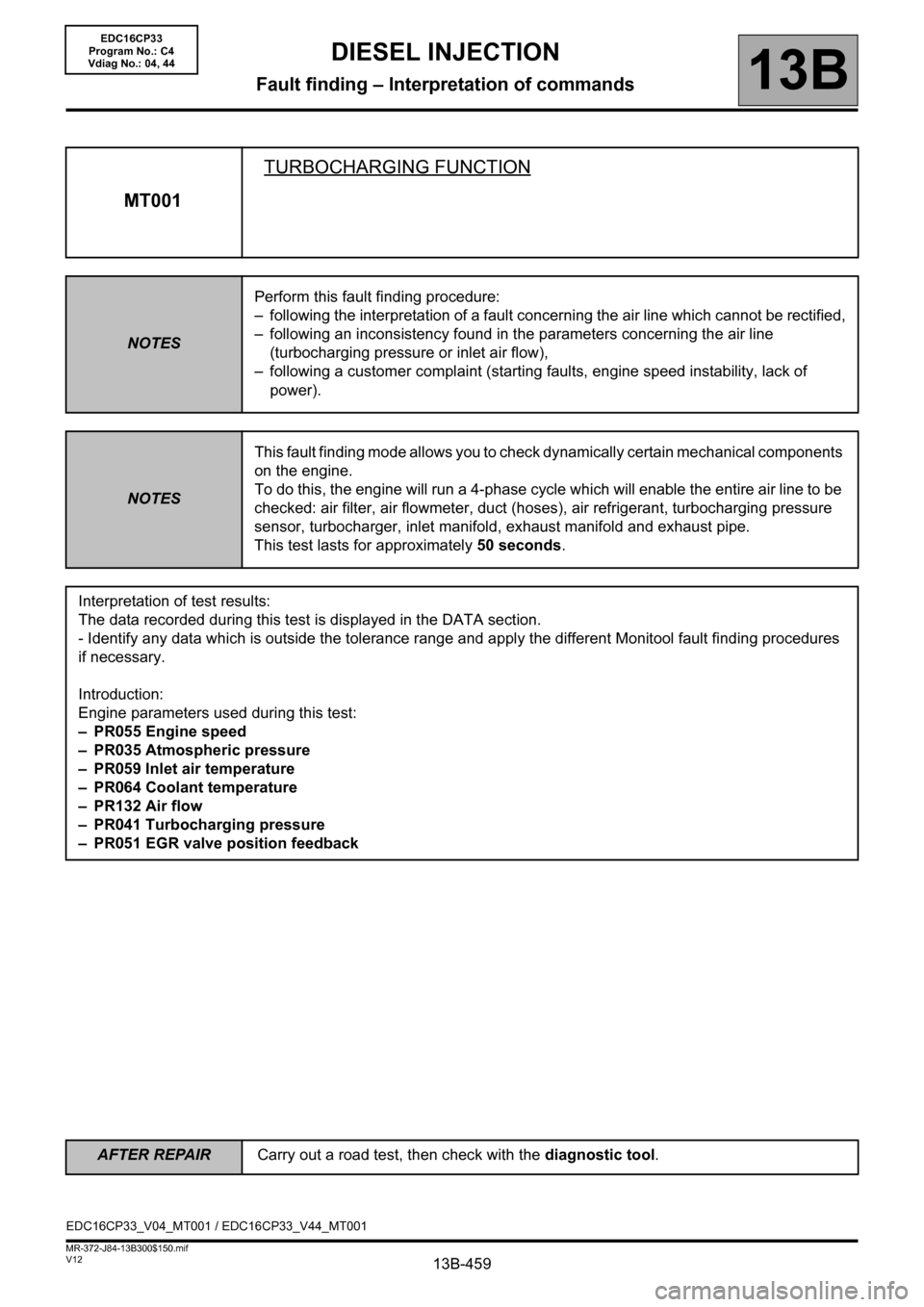
MT001TURBOCHARGING FUNCTION
NOTESPerform this fault finding procedure:
– following the interpretation of a fault concerning the air line which cannot be rectified,
– following an inconsistency found in the parameters concerning the air line
(turbocharging pressure or inlet air flow),
– following a customer complaint (starting faults, engine speed instability, lack of
power).
NOTESThis fault finding mode allows you to check dynamically certain mechanical components
on the engine.
To do this, the engine will run a 4-phase cycle which will enable the entire air line to be
checked: air filter, air flowmeter, duct (hoses), air refrigerant, turbocharging pressure
sensor, turbocharger, inlet manifold, exhaust manifold and exhaust pipe.
This test lasts for approximately 50 seconds.
Interpretation of test results:
The data recorded during this test is displayed in the DATA section.
- Identify any data which is outside the tolerance range and apply the different Monitool fault finding procedures
if necessary.
Introduction:
Engine parameters used during this test:
– PR055 Engine speed
– PR035 Atmospheric pressure
– PR059 Inlet air temperature
– PR064 Coolant temperature
–PR132 Air flow
– PR041 Turbocharging pressure
– PR051 EGR valve position feedback
EDC16CP33_V04_MT001 / EDC16CP33_V44_MT001
EDC16CP33
Program No.: C4
Vdiag No.: 04, 44
AFTER REPAIRCarry out a road test, then check with the diagnostic tool.
Page 462 of 510
13B-462V12 MR-372-J84-13B300$150.mif
DIESEL INJECTION
Fault finding – Interpretation of commands13B
MT001
CONTINUED 3
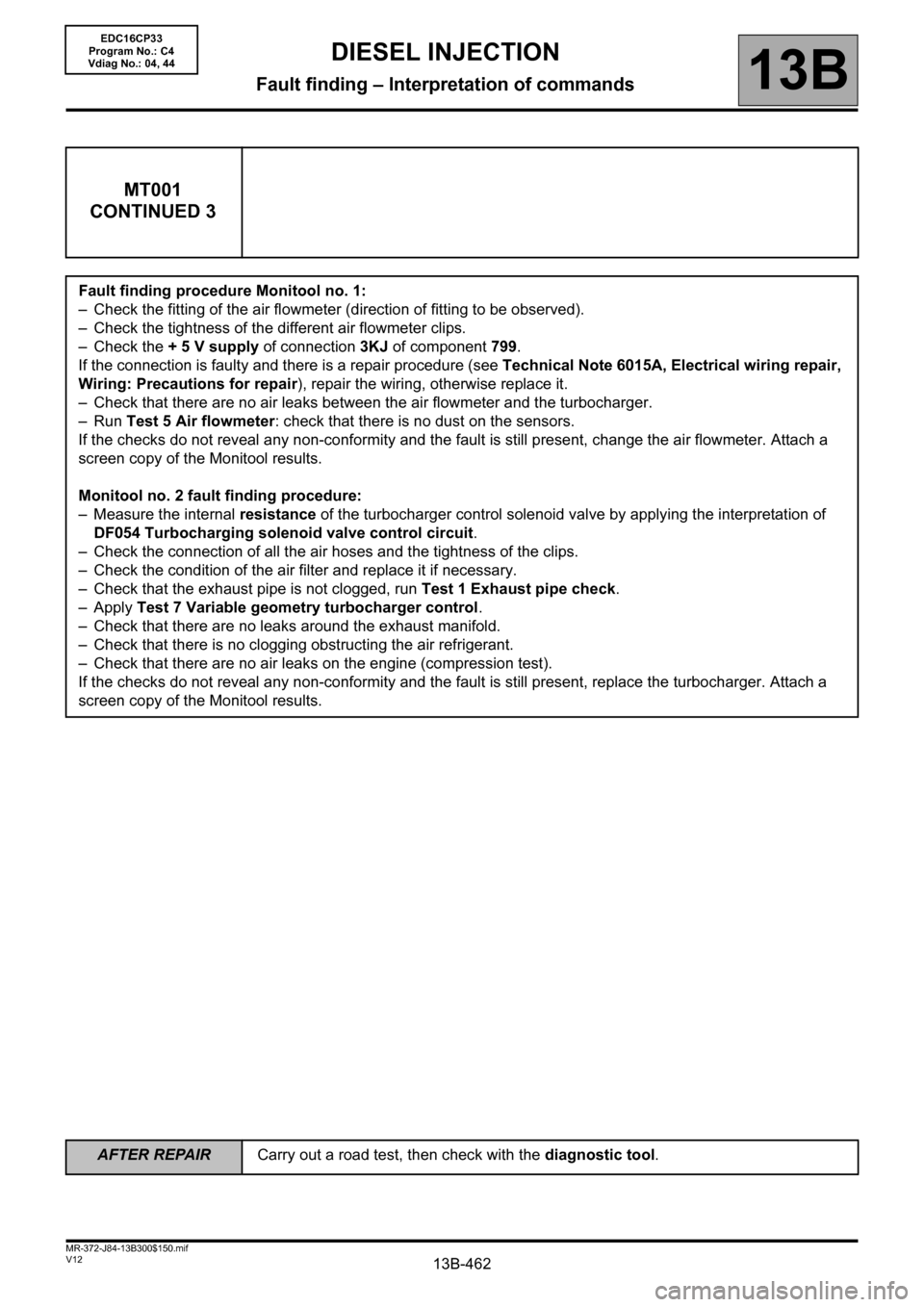
Fault finding procedure Monitool no. 1:
– Check the fitting of the air flowmeter (direction of fitting to be observed).
– Check the tightness of the different air flowmeter clips.
– Check the + 5 V supply of connection 3KJ of component 799.
If the connection is faulty and there is a repair procedure (see Technical Note 6015A, Electrical wiring repair,
Wiring: Precautions for repair), repair the wiring, otherwise replace it.
– Check that there are no air leaks between the air flowmeter and the turbocharger.
– Run Test 5 Air flowmeter: check that there is no dust on the sensors.
If the checks do not reveal any non-conformity and the fault is still present, change the air flowmeter. Attach a
screen copy of the Monitool results.
Monitool no. 2 fault finding procedure:
– Measure the internal resistance of the turbocharger control solenoid valve by applying the interpretation of
DF054 Turbocharging solenoid valve control circuit.
– Check the connection of all the air hoses and the tightness of the clips.
– Check the condition of the air filter and replace it if necessary.
– Check that the exhaust pipe is not clogged, run Test 1 Exhaust pipe check.
–Apply Test 7 Variable geometry turbocharger control.
– Check that there are no leaks around the exhaust manifold.
– Check that there is no clogging obstructing the air refrigerant.
– Check that there are no air leaks on the engine (compression test).
If the checks do not reveal any non-conformity and the fault is still present, replace the turbocharger. Attach a
screen copy of the Monitool results.
EDC16CP33
Program No.: C4
Vdiag No.: 04, 44
AFTER REPAIRCarry out a road test, then check with the diagnostic tool.
Page 469 of 510
13B-469
AFTER REPAIRCarry out a road test followed by a check with the diagnostic tool.
V12 MR-372-J84-13B300$160.mif
13B
EDC16CP33
Program No.: C4
Vdiag No.: 04, 08, 18, 1C,
20, 24, 26, 28, 34, 38, 44,
4C, 54, 58, 5C, 60, 62, 74
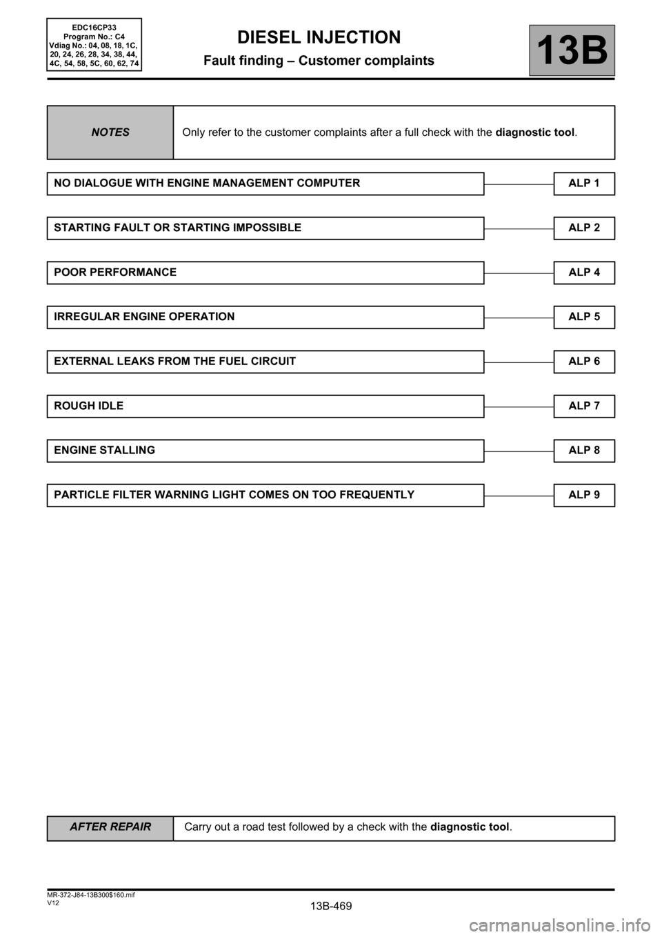
NOTESOnly refer to the customer complaints after a full check with the diagnostic tool.
NO DIALOGUE WITH ENGINE MANAGEMENT COMPUTER ALP 1
STARTING FAULT OR STARTING IMPOSSIBLE ALP 2
POOR PERFORMANCEALP 4
IRREGULAR ENGINE OPERATION ALP 5
EXTERNAL LEAKS FROM THE FUEL CIRCUIT ALP 6
ROUGH IDLEALP 7
ENGINE STALLINGALP 8
PARTICLE FILTER WARNING LIGHT COMES ON TOO FREQUENTLY ALP 9
DIESEL INJECTION
Fault finding – Customer complaints
Page 472 of 510
13B-472
AFTER REPAIRCarry out a road test, then check with the diagnostic tool.
V12 MR-372-J84-13B300$170.mif
DIESEL INJECTION
Fault finding – Fault Finding Chart13B
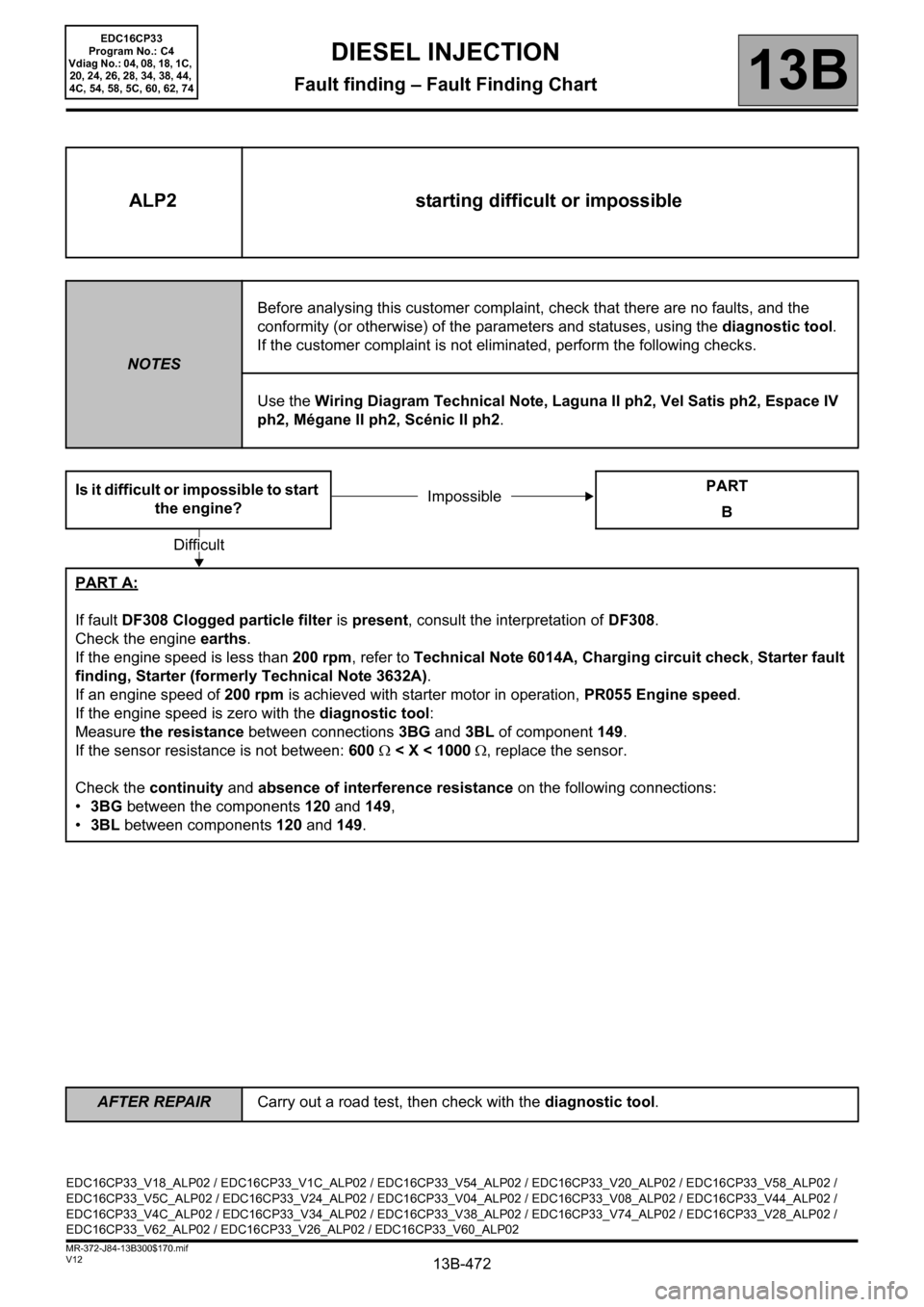
ALP2 starting difficult or impossible
NOTESBefore analysing this customer complaint, check that there are no faults, and the
conformity (or otherwise) of the parameters and statuses, using the diagnostic tool.
If the customer complaint is not eliminated, perform the following checks.
Use the Wiring Diagram Technical Note, Laguna II ph2, Vel Satis ph2, Espace IV
ph2, Mégane II ph2, Scénic II ph2.
Is it difficult or impossible to start
the engine?PART
B
PART A:
If fault DF308 Clogged particle filter is present, consult the interpretation of DF308.
Check the engine earths.
If the engine speed is less than 200 rpm, refer to Technical Note 6014A, Charging circuit check, Starter fault
finding, Starter (formerly Technical Note 3632A).
If an engine speed of 200 rpm is achieved with starter motor in operation, PR055 Engine speed.
If the engine speed is zero with the diagnostic tool:
Measure the resistance between connections 3BG and 3BL of component 149.
If the sensor resistance is not between: 600 Ω < X < 1000 Ω, replace the sensor.
Check the continuity and absence of interference resistance on the following connections:
•3BG between the components 120 and 149,
•3BL between components 120 and 149.
Impossible
Difficult
EDC16CP33_V18_ALP02 / EDC16CP33_V1C_ALP02 / EDC16CP33_V54_ALP02 / EDC16CP33_V20_ALP02 / EDC16CP33_V58_ALP02 /
EDC16CP33_V5C_ALP02 / EDC16CP33_V24_ALP02 / EDC16CP33_V04_ALP02 / EDC16CP33_V08_ALP02 / EDC16CP33_V44_ALP02 /
EDC16CP33_V4C_ALP02 / EDC16CP33_V34_ALP02 / EDC16CP33_V38_ALP02 / EDC16CP33_V74_ALP02 / EDC16CP33_V28_ALP02 /
EDC16CP33_V62_ALP02 / EDC16CP33_V26_ALP02 / EDC16CP33_V60_ALP02
EDC16CP33
Program No.: C4
Vdiag No.: 04, 08, 18, 1C,
20, 24, 26, 28, 34, 38, 44,
4C, 54, 58, 5C, 60, 62, 74
Page 475 of 510
13B-475
AFTER REPAIRCarry out a road test, then check with the diagnostic tool.
V12 MR-372-J84-13B300$170.mif
DIESEL INJECTION
Fault finding – Fault Finding Chart13B
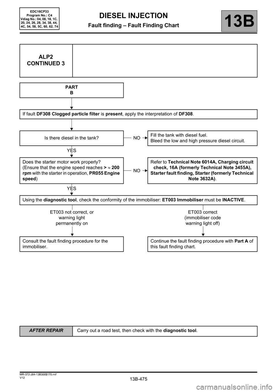
ALP2
CONTINUED 3
PART
B
If fault DF308 Clogged particle filter is present, apply the interpretation of DF308.
Is there diesel in the tank?Fill the tank with diesel fuel.
Bleed the low and high pressure diesel circuit.
Does the starter motor work properly?
(Ensure that the engine speed reaches > ≈ 200
rpm with the starter in operation, PR055 Engine
speed)Refer to Technical Note 6014A, Charging circuit
check, 16A (formerly Technical Note 3455A),
Starter fault finding, Starter (formerly Technical
Note 3632A).
Using the diagnostic tool, check the conformity of the immobiliser: ET003 Immobiliser must be INACTIVE.
Consult the fault finding procedure for the
immobiliser.Continue the fault finding procedure with Part A of
this fault finding chart.
NO
YES
NO
YES
ET003 not correct, or
warning light
permanently onET003 correct
(immobiliser code
warning light off)
EDC16CP33
Program No.: C4
Vdiag No.: 04, 08, 18, 1C,
20, 24, 26, 28, 34, 38, 44,
4C, 54, 58, 5C, 60, 62, 74
Page 477 of 510
13B-477
AFTER REPAIRCarry out a road test, then check with the diagnostic tool.
V12 MR-372-J84-13B300$170.mif
DIESEL INJECTION
Fault finding – Fault Finding Chart13B
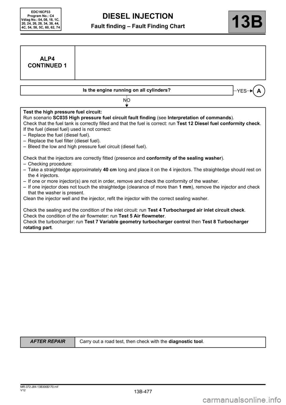
ALP4
CONTINUED 1
Is the engine running on all cylinders?
Test the high pressure fuel circuit:
Run scenario SC035 High pressure fuel circuit fault finding (see Interpretation of commands).
Check that the fuel tank is correctly filled and that the fuel is correct: run Test 12 Diesel fuel conformity check.
If the fuel (diesel fuel) used is not correct:
– Replace the fuel (diesel fuel).
– Replace the fuel filter (diesel fuel).
– Bleed the low and high pressure fuel circuit (diesel fuel).
Check that the injectors are correctly fitted (presence and conformity of the sealing washer).
– Checking procedure:
– Take a straightedge approximately 40 cm long and place it on the 4 injectors. The straightedge should rest on
the 4 injectors.
– If one or more injector(s) are not in order, remove and check the conformity of the washer.
– If one injector does not touch the straightedge (clearance of more than 1mm), remove the injector and check
that the washer is present.
Clean the injector well and the injector, refit the injector with the correct sealing washer.
Check the sealing and the condition of the inlet circuit: run Test 4 Turbocharged air inlet circuit check.
Check the condition of the air flowmeter: run Test 5 Air flowmeter.
Check the turbocharger: run Test 7 Variable geometry turbocharger control then Test 8 Turbocharger
rotating part.AYES
NO
EDC16CP33
Program No.: C4
Vdiag No.: 04, 08, 18, 1C,
20, 24, 26, 28, 34, 38, 44,
4C, 54, 58, 5C, 60, 62, 74
Page 478 of 510
13B-478
AFTER REPAIRCarry out a road test, then check with the diagnostic tool.
V12 MR-372-J84-13B300$170.mif
DIESEL INJECTION
Fault finding – Fault Finding Chart13B
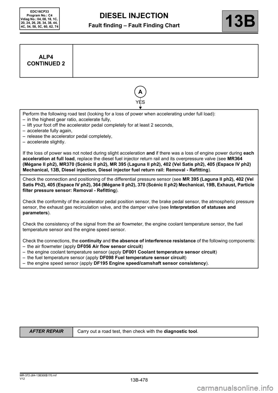
ALP4
CONTINUED 2
Perform the following road test (looking for a loss of power when accelerating under full load):
– in the highest gear ratio, accelerate fully,
– lift your foot off the accelerator pedal completely for at least 2 seconds,
– accelerate fully again,
– release the accelerator pedal completely,
– accelerate slightly.
If the loss of power was not noted during slight acceleration and if there was a loss of engine power during each
acceleration at full load, replace the diesel fuel injector return rail and its overpressure valve (see MR364
(Mégane II ph2), MR370 (Scénic II ph2), MR 395 (Laguna II ph2), 402 (Vel Satis ph2), 405 (Espace IV ph2)
Mechanical, 13B, Diesel injection, Diesel injector fuel return rail: Removal - Refitting).
Check the connection and positioning of the differential pressure sensor (see MR 395 (Laguna II ph2), 402 (Vel
Satis Ph2), 405 (Espace IV ph2), 364 (Mégane II ph2), 370 (Scénic II ph2) Mechanical, 19B, Exhaust, Particle
filter pressure sensor: Removal - Refitting).
Check the conformity of the accelerator pedal position sensor, the brake pedal sensor, the atmospheric pressure
sensor, the exhaust gas recirculation valve, and the damper valve (see Interpretation of statuses and
parameters).
Check the consistency of the signal from the air flowmeter, the engine coolant temperature sensor, the fuel
temperature sensor and the engine speed sensor.
Check the connections, the continuity and the absence of interference resistance of the following components:
– the air flowmeter (apply DF056 Air flow sensor circuit)
– the engine coolant temperature sensor (apply DF001 Coolant temperature sensor circuit)
– the fuel temperature sensor (apply DF098 Fuel temperature sensor circuit)
– the engine speed sensor (apply DF195 Engine speed/camshaft sensor consistency).
A
YES
EDC16CP33
Program No.: C4
Vdiag No.: 04, 08, 18, 1C,
20, 24, 26, 28, 34, 38, 44,
4C, 54, 58, 5C, 60, 62, 74
Page 479 of 510
13B-479
AFTER REPAIRCarry out a road test, then check with the diagnostic tool.
V12 MR-372-J84-13B300$170.mif
DIESEL INJECTION
Fault finding – Fault Finding Chart13B
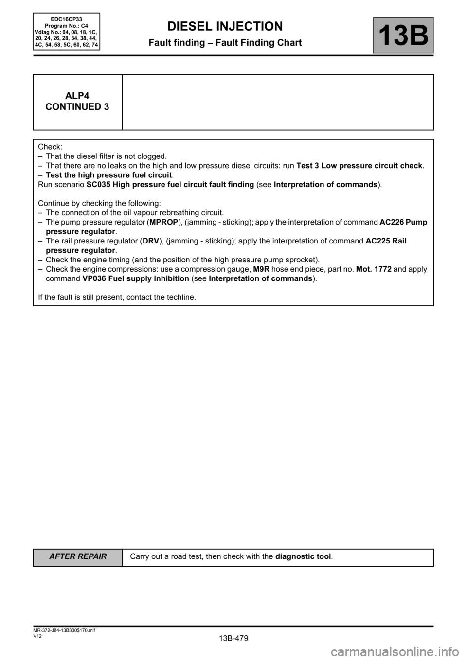
ALP4
CONTINUED 3
Check:
– That the diesel filter is not clogged.
– That there are no leaks on the high and low pressure diesel circuits: run Test 3 Low pressure circuit check.
–Test the high pressure fuel circuit:
Run scenario SC035 High pressure fuel circuit fault finding (see Interpretation of commands).
Continue by checking the following:
– The connection of the oil vapour rebreathing circuit.
– The pump pressure regulator (MPROP), (jamming - sticking); apply the interpretation of command AC226 Pump
pressure regulator.
– The rail pressure regulator (DRV), (jamming - sticking); apply the interpretation of command AC225 Rail
pressure regulator.
– Check the engine timing (and the position of the high pressure pump sprocket).
– Check the engine compressions: use a compression gauge, M9R hose end piece, part no. Mot. 1772 and apply
command VP036 Fuel supply inhibition (see Interpretation of commands).
If the fault is still present, contact the techline.
EDC16CP33
Program No.: C4
Vdiag No.: 04, 08, 18, 1C,
20, 24, 26, 28, 34, 38, 44,
4C, 54, 58, 5C, 60, 62, 74
Page 481 of 510
13B-481
AFTER REPAIRCarry out a road test, then check with the diagnostic tool.
V12 MR-372-J84-13B300$170.mif
DIESEL INJECTION
Fault finding – Fault Finding Chart13B
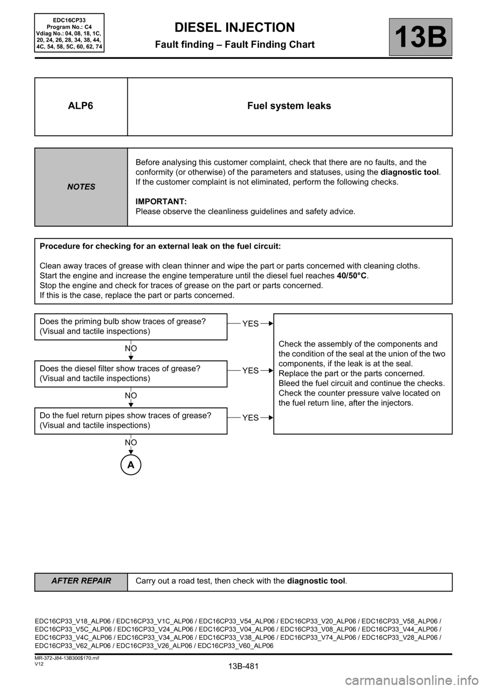
ALP6 Fuel system leaks
NOTESBefore analysing this customer complaint, check that there are no faults, and the
conformity (or otherwise) of the parameters and statuses, using the diagnostic tool.
If the customer complaint is not eliminated, perform the following checks.
IMPORTANT:
Please observe the cleanliness guidelines and safety advice.
Procedure for checking for an external leak on the fuel circuit:
Clean away traces of grease with clean thinner and wipe the part or parts concerned with cleaning cloths.
Start the engine and increase the engine temperature until the diesel fuel reaches 40/50°C.
Stop the engine and check for traces of grease on the part or parts concerned.
If this is the case, replace the part or parts concerned.
Does the priming bulb show traces of grease?
(Visual and tactile inspections)
Check the assembly of the components and
the condition of the seal at the union of the two
components, if the leak is at the seal.
Replace the part or the parts concerned.
Bleed the fuel circuit and continue the checks.
Check the counter pressure valve located on
the fuel return line, after the injectors. Does the diesel filter show traces of grease?
(Visual and tactile inspections)
Do the fuel return pipes show traces of grease?
(Visual and tactile inspections)
YES
NO
YES
NO
YES
NO
A
EDC16CP33_V18_ALP06 / EDC16CP33_V1C_ALP06 / EDC16CP33_V54_ALP06 / EDC16CP33_V20_ALP06 / EDC16CP33_V58_ALP06 /
EDC16CP33_V5C_ALP06 / EDC16CP33_V24_ALP06 / EDC16CP33_V04_ALP06 / EDC16CP33_V08_ALP06 / EDC16CP33_V44_ALP06 /
EDC16CP33_V4C_ALP06 / EDC16CP33_V34_ALP06 / EDC16CP33_V38_ALP06 / EDC16CP33_V74_ALP06 / EDC16CP33_V28_ALP06 /
EDC16CP33_V62_ALP06 / EDC16CP33_V26_ALP06 / EDC16CP33_V60_ALP06
EDC16CP33
Program No.: C4
Vdiag No.: 04, 08, 18, 1C,
20, 24, 26, 28, 34, 38, 44,
4C, 54, 58, 5C, 60, 62, 74
Page 485 of 510
13B-485
AFTER REPAIRCarry out a road test, then check with the diagnostic tool.
V12 MR-372-J84-13B300$170.mif
DIESEL INJECTION
Fault finding – Fault Finding Chart13B
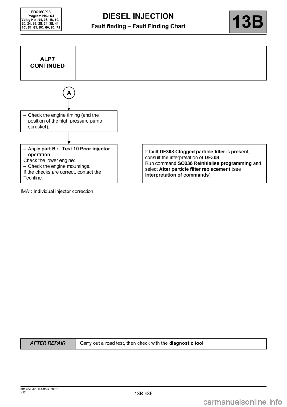
IMA*: Individual injector correction
ALP7
CONTINUED
– Check the engine timing (and the
position of the high pressure pump
sprocket).
–Apply part B of Test 10 Poor injector
operation.
Check the lower engine:
– Check the engine mountings.
If the checks are correct, contact the
Techline.If fault DF308 Clogged particle filter is present,
consult the interpretation of DF308.
Run command SC036 Reinitialise programming and
select After particle filter replacement (see
Interpretation of commands).
A
EDC16CP33
Program No.: C4
Vdiag No.: 04, 08, 18, 1C,
20, 24, 26, 28, 34, 38, 44,
4C, 54, 58, 5C, 60, 62, 74