RENAULT SCENIC 2012 J95 / 3.G Engine And Peripherals EDC16CP33 Workshop Manual
Manufacturer: RENAULT, Model Year: 2012, Model line: SCENIC, Model: RENAULT SCENIC 2012 J95 / 3.GPages: 510, PDF Size: 2.98 MB
Page 101 of 510
13B-101
AFTER REPAIRDeal with any other faults. Clear the fault memory.
Switch off the ignition until the end of the power-latch phase, and carry out a road test
followed by a check with the diagnostic tool.
V12 MR-372-J84-13B300$072.mif
DIESEL INJECTION
Fault finding – Interpretation of faults13B
EDC16CP33
Program No.: C4
Vdiag No.: 04, 08, 18, 1C,
20, 24, 26, 28, 34, 38, 44,
4C, 54, 58, 5C, 60, 62, 74
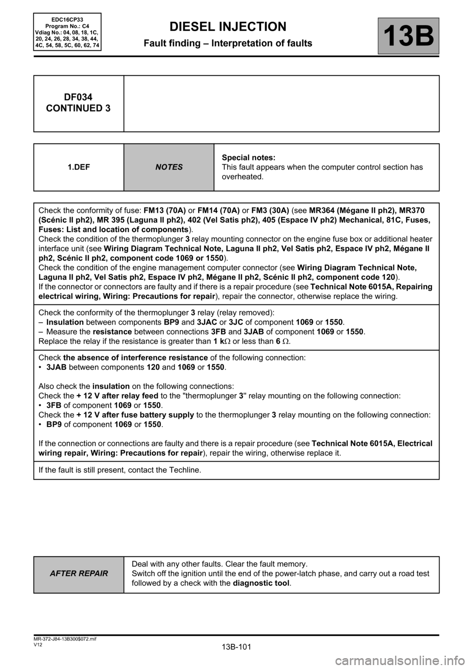
DF034
CONTINUED 3
1.DEFNOTESSpecial notes:
This fault appears when the computer control section has
overheated.
Check the conformity of fuse: FM13 (70A) or FM14 (70A) or FM3 (30A) (see MR364 (Mégane II ph2), MR370
(Scénic II ph2), MR 395 (Laguna II ph2), 402 (Vel Satis ph2), 405 (Espace IV ph2) Mechanical, 81C, Fuses,
Fuses: List and location of components).
Check the condition of the thermoplunger 3 relay mounting connector on the engine fuse box or additional heater
interface unit (see Wiring Diagram Technical Note, Laguna II ph2, Vel Satis ph2, Espace IV ph2, Mégane II
ph2, Scénic II ph2, component code 1069 or 1550).
Check the condition of the engine management computer connector (see Wiring Diagram Technical Note,
Laguna II ph2, Vel Satis ph2, Espace IV ph2, Mégane II ph2, Scénic II ph2, component code 120).
If the connector or connectors are faulty and if there is a repair procedure (see Technical Note 6015A, Repairing
electrical wiring, Wiring: Precautions for repair), repair the connector, otherwise replace the wiring.
Check the conformity of the thermoplunger 3 relay (relay removed):
–Insulation between components BP9 and 3JAC or 3JC of component 1069 or 1550.
– Measure the resistance between connections 3FB and 3JAB of component 1069 or 1550.
Replace the relay if the resistance is greater than 1 kΩ or less than 6 Ω.
Check the absence of interference resistance of the following connection:
•3JAB between components 120 and 1069 or 1550.
Also check the insulation on the following connections:
Check the + 12 V after relay feed to the "thermoplunger 3'' relay mounting on the following connection:
•3FB of component 1069 or
1550.
Check the + 12 V after fuse battery supply to the thermoplunger 3 relay mounting on the following connection:
•BP9 of component 1069 or 1550.
If the connection or connections are faulty and there is a repair procedure (see Technical Note 6015A, Electrical
wiring repair, Wiring: Precautions for repair), repair the wiring, otherwise replace it.
If the fault is still present, contact the Techline.
Page 102 of 510
13B-102
AFTER REPAIRDeal with any other faults. Clear the fault memory.
Switch off the ignition until the end of the power-latch phase, and carry out a road test
followed by a check with the diagnostic tool.
V12 MR-372-J84-13B300$072.mif
DIESEL INJECTION
Fault finding – Interpretation of faults13B
EDC16CP33
Program No.: C4
Vdiag No.: 04, 08, 18, 1C,
20, 24, 26, 28, 34, 38, 44,
4C, 54, 58, 5C, 60, 62, 74
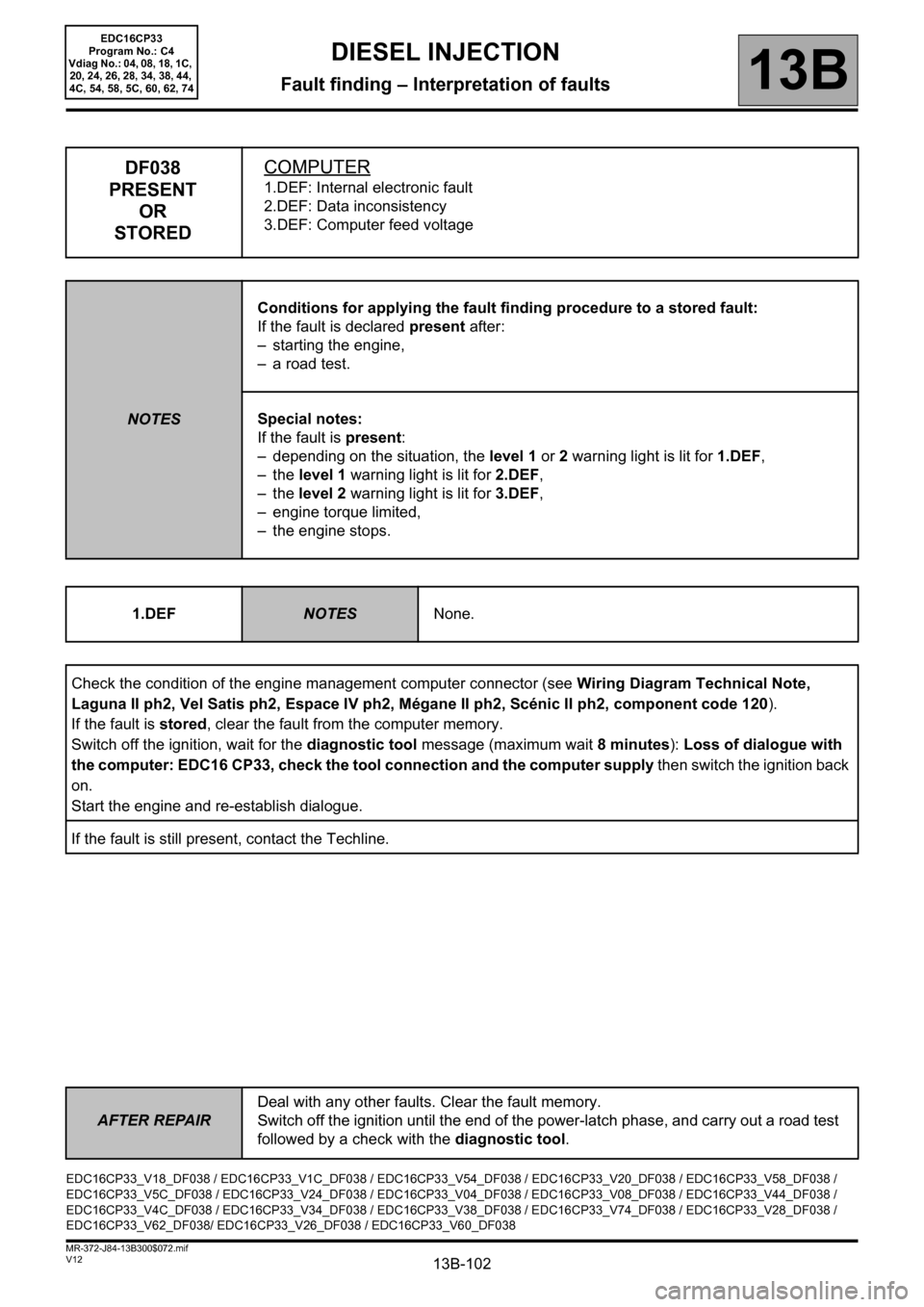
DF038
PRESENT
OR
STOREDCOMPUTER
1.DEF: Internal electronic fault
2.DEF: Data inconsistency
3.DEF: Computer feed voltage
NOTESConditions for applying the fault finding procedure to a stored fault:
If the fault is declared present after:
– starting the engine,
– a road test.
Special notes:
If the fault is present:
– depending on the situation, the level 1 or 2 warning light is lit for 1.DEF,
–the level 1 warning light is lit for 2.DEF,
–the level 2 warning light is lit for 3.DEF,
– engine torque limited,
– the engine stops.
1.DEF
NOTESNone.
Check the condition of the engine management computer connector (see Wiring Diagram Technical Note,
Laguna II ph2, Vel Satis ph2, Espace IV ph2, Mégane II ph2, Scénic II ph2, component code 120).
If the fault is stored, clear the fault from the computer memory.
Switch off the ignition, wait for the diagnostic tool message (maximum wait 8 minutes): Loss of dialogue with
the computer: EDC16 CP33, check the tool connection and the computer supply then switch the ignition back
on.
Start the engine and re-establish dialogue.
If the fault is still present, contact the Techline.
EDC16CP33_V18_DF038 / EDC16CP33_V1C_DF038 / EDC16CP33_V54_DF038 / EDC16CP33_V20_DF038 / EDC16CP33_V58_DF038 /
EDC16CP33_V5C_DF038 / EDC16CP33_V24_DF038 / EDC16CP33_V04_DF038 / EDC16CP33_V08_DF038 / EDC16CP33_V44_DF038 /
EDC16CP33_V4C_DF038 / EDC16CP33_V34_DF038 / EDC16CP33_V38_DF038 / EDC16CP33_V74_DF038 / EDC16CP33_V28_DF038 /
EDC16CP33_V62_DF038/ EDC16CP33_V26_DF038 / EDC16CP33_V60_DF038
Page 103 of 510
13B-103
AFTER REPAIRDeal with any other faults. Clear the fault memory.
Switch off the ignition until the end of the power-latch phase, and carry out a road test
followed by a check with the diagnostic tool.
V12 MR-372-J84-13B300$072.mif
DIESEL INJECTION
Fault finding – Interpretation of faults13B
EDC16CP33
Program No.: C4
Vdiag No.: 04, 08, 18, 1C,
20, 24, 26, 28, 34, 38, 44,
4C, 54, 58, 5C, 60, 62, 74
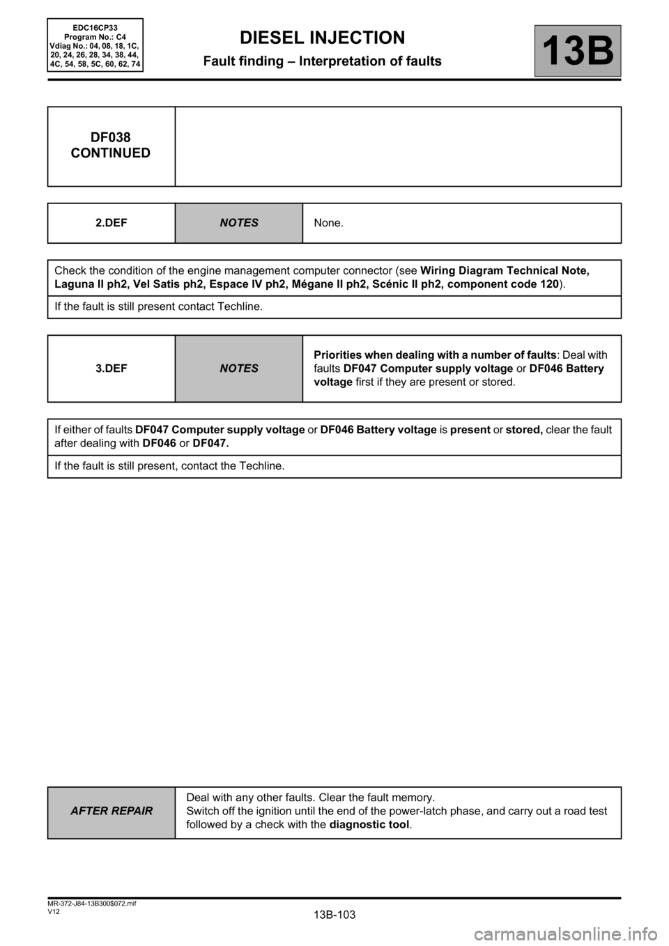
DF038
CONTINUED
2.DEFNOTESNone.
Check the condition of the engine management computer connector (see Wiring Diagram Technical Note,
Laguna II ph2, Vel Satis ph2, Espace IV ph2, Mégane II ph2, Scénic II ph2, component code 120).
If the fault is still present contact Techline.
3.DEF
NOTES
Priorities when dealing with a number of faults: Deal with
faults
DF047 Computer supply voltage or DF046 Battery
voltage
first if they are present or stored.
If either of faults DF047 Computer supply voltage or DF046 Battery voltage is present or stored, clear the fault
after dealing with DF046 or DF047.
If the fault is still present, contact the Techline.
Page 104 of 510
13B-104
AFTER REPAIRDeal with any other faults. Clear the fault memory.
Switch off the ignition until the end of the power-latch phase, and carry out a road test
followed by a check with the diagnostic tool.
V12 MR-372-J84-13B300$072.mif
DIESEL INJECTION
Fault finding – Interpretation of faults13B
EDC16CP33
Program No.: C4
Vdiag No.: 04, 08, 18, 1C,
20, 24, 26, 28, 34, 38, 44,
4C, 54, 58, 5C, 60, 62, 74
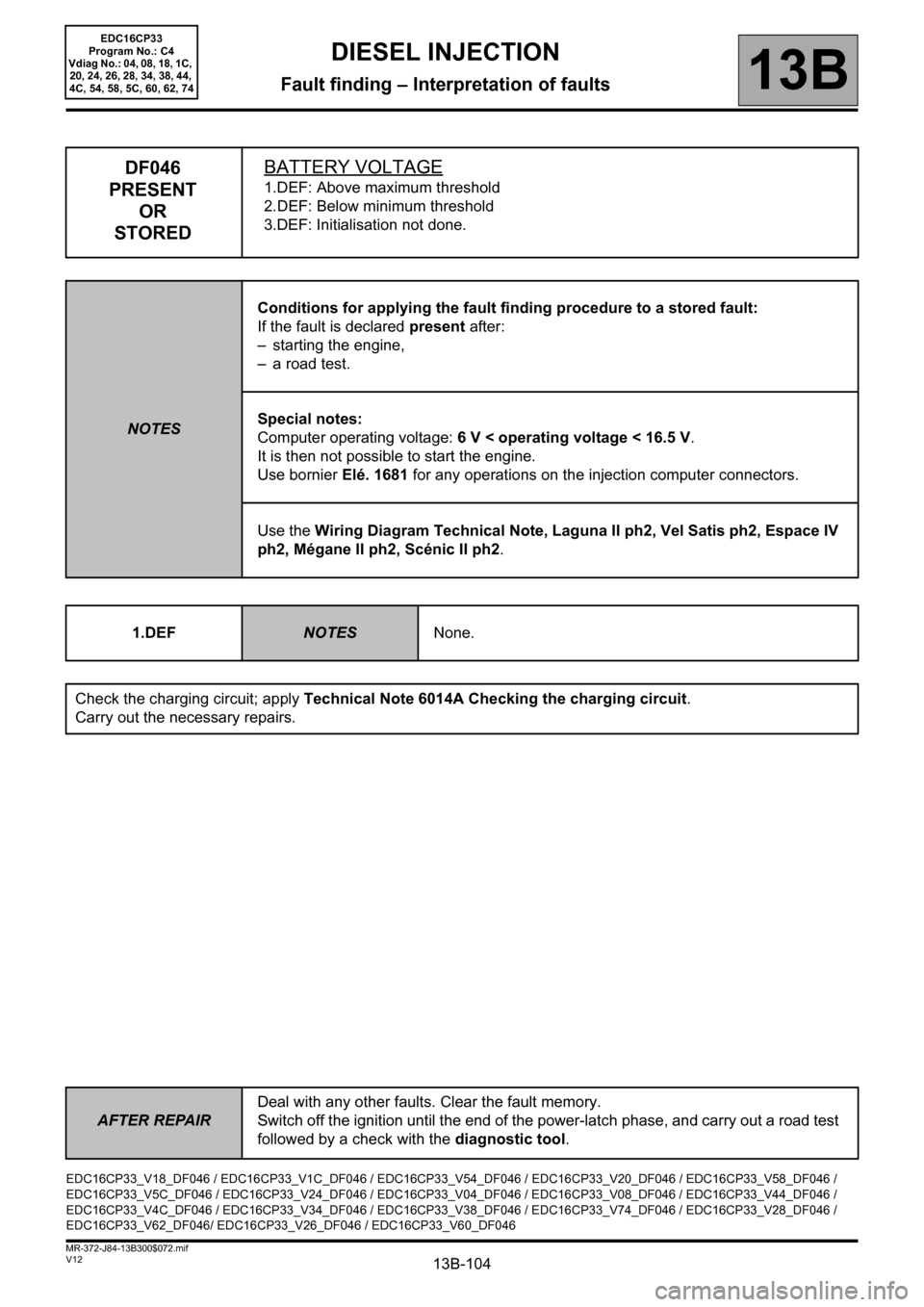
DF046
PRESENT
OR
STOREDBATTERY VOLTAGE
1.DEF: Above maximum threshold
2.DEF: Below minimum threshold
3.DEF: Initialisation not done.
NOTESConditions for applying the fault finding procedure to a stored fault:
If the fault is declared present after:
– starting the engine,
– a road test.
Special notes:
Computer operating voltage: 6 V < operating voltage < 16.5 V.
It is then not possible to start the engine.
Use bornier Elé. 1681 for any operations on the injection computer connectors.
Use the Wiring Diagram Technical Note, Laguna II ph2, Vel Satis ph2, Espace IV
ph2, Mégane II ph2, Scénic II ph2.
1.DEF
NOTESNone.
Check the charging circuit; apply Technical Note 6014A Checking the charging circuit.
Carry out the necessary repairs.
EDC16CP33_V18_DF046 / EDC16CP33_V1C_DF046 / EDC16CP33_V54_DF046 / EDC16CP33_V20_DF046 / EDC16CP33_V58_DF046 /
EDC16CP33_V5C_DF046 / EDC16CP33_V24_DF046 / EDC16CP33_V04_DF046 / EDC16CP33_V08_DF046 / EDC16CP33_V44_DF046 /
EDC16CP33_V4C_DF046 / EDC16CP33_V34_DF046 / EDC16CP33_V38_DF046 / EDC16CP33_V74_DF046 / EDC16CP33_V28_DF046 /
EDC16CP33_V62_DF046/ EDC16CP33_V26_DF046 / EDC16CP33_V60_DF046
Page 105 of 510
13B-105
AFTER REPAIRDeal with any other faults. Clear the fault memory.
Switch off the ignition until the end of the power-latch phase, and carry out a road test
followed by a check with the diagnostic tool.
V12 MR-372-J84-13B300$072.mif
DIESEL INJECTION
Fault finding – Interpretation of faults13B
EDC16CP33
Program No.: C4
Vdiag No.: 04, 08, 18, 1C,
20, 24, 26, 28, 34, 38, 44,
4C, 54, 58, 5C, 60, 62, 74
DF046
CONTINUED
2.DEFNOTESNone.
Using a voltmeter, take a reading of the battery voltage at its terminals.
Compare this value with the value displayed by the diagnostic tool PR074 Battery voltage.
If there is no difference (less than 1 V):
– Recharge and test the battery. If it is faulty, replace it.
– Check the charging circuit: Technical Note 6014A Checking the charging circuit.
If there is a difference (greater than 1 V):
– Check the tightness and the condition of the battery terminals.
Using the appropriate wiring diagram:
–Check the continuity and absence of interference resistance on the following connection:
•3FB between components 120 and 983 or 1337.
Check the conformity of the earths on connections NT of component 120.
If the connection or connections are faulty and if there is a repair method (see Technical Note 6015A, Electrical
wiring repair, Wiring: Precautions for repair), repair the wiring, otherwise replace the wiring.
3.DEF
NOTESOnly deal with this fault when it is present.
Switch off the ignition, wait for the diagnostic tool message (maximum wait 8 min): Loss of dialogue with the
computer: EDC16 CP33, check the tool connection and the computer supply voltage then switch on the
ignition again and check whether the fault is still present.
If the fault is still present, contact the Techline.
Page 106 of 510
13B-106
AFTER REPAIRDeal with any other faults. Clear the fault memory.
Switch off the ignition until the end of the power-latch phase, and carry out a road test
followed by a check with the diagnostic tool.
V12 MR-372-J84-13B300$072.mif
DIESEL INJECTION
Fault finding – Interpretation of faults13B
EDC16CP33
Program No.: C4
Vdiag No.: 04, 08, 18, 1C,
20, 24, 26, 28, 34, 38, 44,
4C, 54, 58, 5C, 60, 62, 74
DF047
PRESENT
OR
STOREDCOMPUTER SUPPLY VOLTAGE
1.DEF: Voltage outside permitted range of values
NOTESConditions for applying the fault finding procedure to a stored fault:
If the fault is declared present after:
– starting the engine,
– a road test.
Special notes:
Use bornier Elé.1681 for any operations on the injection computer connectors.
Use the Wiring Diagram Technical Note, Laguna II ph2, Vel Satis ph2, Espace IV
ph2, Mégane II ph2, Scénic II ph2.
Check the tightness and the condition of the battery terminals.
Using the appropriate wiring diagram:
–Check the continuity and absence of interference resistance on the following connection:
•3FB between components 120 and 983 or 1337.
Check the conformity of the earths on connections NT of component 120.
If the connection or connections are faulty and if there is a repair method (see Technical Note 6015A, Electrical
wiring repair, Wiring: Precautions for repair), repair the wiring, otherwise replace the wiring.
EDC16CP33_V18_DF047 / EDC16CP33_V1C_DF047 / EDC16CP33_V54_DF047 / EDC16CP33_V20_DF047 / EDC16CP33_V58_DF047 /
EDC16CP33_V5C_DF047 / EDC16CP33_V24_DF047 / EDC16CP33_V04_DF047 / EDC16CP33_V08_DF047 / EDC16CP33_V44_DF047 /
EDC16CP33_V4C_DF047 / EDC16CP33_V34_DF047 / EDC16CP33_V38_DF047 / EDC16CP33_V74_DF047 / EDC16CP33_V28_DF047 /
EDC16CP33_V62_DF047/ EDC16CP33_V26_DF047 / EDC16CP33_V60_DF047
Page 107 of 510
13B-107
AFTER REPAIRDeal with any other faults. Clear the fault memory.
Switch off the ignition until the end of the power-latch phase, and carry out a road test
followed by a check with the diagnostic tool.
V12 MR-372-J84-13B300$072.mif
DIESEL INJECTION
Fault finding – Interpretation of faults13B
EDC16CP33
Program No.: C4
Vdiag No.: 04, 08, 18, 1C,
20, 24, 26, 28, 34, 38, 44,
4C, 54, 58, 5C, 60, 62, 74
DF051
STOREDCRUISE CONTROL/SPEED LIMITER1.DEF: Cruise control/speed limiter steering wheel control
NOTESPriority when dealing with a number of faults:
– DF196 Pedal sensor circuit gang 1
– DF198 Pedal sensor circuit gang 2.
Conditions for applying the fault finding procedure to a stored fault:
If the fault is declared present after:
– a road test with activation of the cruise control/speed limiter function,
– the engine is started.
Special notes:
If the fault is present:
– the cruise control/speed limiter function is switched off.
Use bornier Elé. 1681 for any operations on the injection computer connectors.
Use the Wiring Diagram Technical Note, Laguna II ph2, Vel Satis ph2, Espace IV
ph2, Mégane II ph2, Scénic II ph2.
If the wiring of the particle filter downstream temperature sensor, component code 1288, is present (with or without
the sensor being present), check the electrical insulation in relation to + 12 V between the following connections:
–3XU between components 120 and 1288,
–3TG between components 120 and 1288.
If the connection or connections are faulty and there is a repair procedure (see Technical Note 6015A, Electrical
wiring repair, Wiring: Precautions for repair), repair the wiring, otherwise replace it.
EDC16CP33_V18_DF051M / EDC16CP33_V1C_DF051M / EDC16CP33_V54_DF051M / EDC16CP33_V20_DF051M /
EDC16CP33_V58_DF051M / EDC16CP33_V5C_DF051M / EDC16CP33_V24_DF051M / EDC16CP33_V04_DF051M /
EDC16CP33_V08_DF051M / EDC16CP33_V44_DF051M / EDC16CP33_V4C_DF051M / EDC16CP33_V34_DF051M /
EDC16CP33_V38_DF051M / EDC16CP33_V74_DF051M / EDC16CP33_V28_DF051M / EDC16CP33_V62_DF051M /
EDC16CP33_V26_DF051M / EDC16CP33_V60_DF051M
Page 108 of 510
13B-108
AFTER REPAIRDeal with any other faults. Clear the fault memory.
Switch off the ignition until the end of the power-latch phase, and carry out a road test
followed by a check with the diagnostic tool.
V12 MR-372-J84-13B300$072.mif
DIESEL INJECTION
Fault finding – Interpretation of faults13B
EDC16CP33
Program No.: C4
Vdiag No.: 04, 08, 18, 1C,
20, 24, 26, 28, 34, 38, 44,
4C, 54, 58, 5C, 60, 62, 74
DF051
CONTINUED
Check the conformity of the steering wheel controls as follows: disconnect connector689 under the centre cover
of the steering wheel (ohmmeter connected on the steering wheel control side). The measurement should read:
•890 Ω < X < 910 Ω when the Resume button is pressed.
(or the one-touch switch R on the right-hand side of the steering wheel)
•0 Ω < X < 0.8 Ω when the Suspend button is pressed.
(or the one-touch switch O on the right-hand side of the steering wheel)
•290 Ω < X < 310 Ω when the Set + button is pressed.
(or the one-touch switch on the left of the steering wheel)
•90 Ω < X < 110 Ω when the Set - button is pressed.
(or the one-touch switch on the left of the steering wheel)
•Infinite resistance in rest position.
– If the values are not correct, replace the controls on the steering wheel.
– If the values are correct, take the same measurements on connections86G and 86M from component120
(steering wheel control connector connected).
If the connection or connections are faulty and if there is a repair method (see Technical Note 6015A, Electrical
wiring repair, Wiring: Precautions for repair), repair the wiring, otherwise replace the wiring.
If the values are correct, clear the fault, switch off the ignition, wait for the diagnostic tool message (maximum
wait 8 min): Loss of dialogue with the computer: EDC16 CP33, check the tool connection and the computer
supply voltage and switch on the ignition again.
If the fault is still present (after pressing the steering wheel controls), contact the Techline.
Page 109 of 510
13B-109
AFTER REPAIRDeal with any other faults. Clear the fault memory.
Switch off the ignition until the end of the power-latch phase, and carry out a road test
followed by a check with the diagnostic tool.
V12 MR-372-J84-13B300$072.mif
DIESEL INJECTION
Fault finding – Interpretation of faults13B
EDC16CP33
Program No.: C4
Vdiag No.: 04, 08, 18, 1C,
20, 24, 26, 28, 34, 38, 44,
4C, 54, 58, 5C, 60, 62, 74
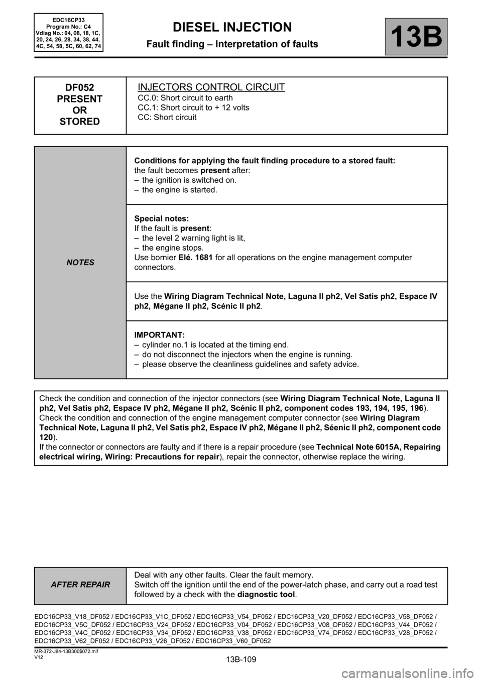
DF052
PRESENT
OR
STOREDINJECTORS CONTROL CIRCUIT
CC.0: Short circuit to earth
CC.1: Short circuit to + 12 volts
CC: Short circuit
NOTESConditions for applying the fault finding procedure to a stored fault:
the fault becomes present after:
– the ignition is switched on.
– the engine is started.
Special notes:
If the fault is present:
– the level 2 warning light is lit,
– the engine stops.
Use bornier Elé. 1681 for all operations on the engine management computer
connectors.
Use the Wiring Diagram Technical Note, Laguna II ph2, Vel Satis ph2, Espace IV
ph2, Mégane II ph2, Scénic II ph2.
IMPORTANT:
– cylinder no.1 is located at the timing end.
– do not disconnect the injectors when the engine is running.
– please observe the cleanliness guidelines and safety advice.
Check the condition and connection of the injector connectors (see Wiring Diagram Technical Note, Laguna II
ph2, Vel Satis ph2, Espace IV ph2, Mégane II ph2, Scénic II ph2, component codes 193, 194, 195, 196).
Check the condition and connection of the engine management computer connector (see Wiring Diagram
Technical Note, Laguna II ph2, Vel Satis ph2, Espace IV ph2, Mégane II ph2, Séenic II ph2, component code
120).
If the connector or connectors are faulty and if there is a repair procedure (see Technical Note 6015A, Repairing
electrical wiring, Wiring: Precautions for repair), repair the connector, otherwise replace the wiring.
EDC16CP33_V18_DF052 / EDC16CP33_V1C_DF052 / EDC16CP33_V54_DF052 / EDC16CP33_V20_DF052 / EDC16CP33_V58_DF052 /
EDC16CP33_V5C_DF052 / EDC16CP33_V24_DF052 / EDC16CP33_V04_DF052 / EDC16CP33_V08_DF052 / EDC16CP33_V44_DF052 /
EDC16CP33_V4C_DF052 / EDC16CP33_V34_DF052 / EDC16CP33_V38_DF052 / EDC16CP33_V74_DF052 / EDC16CP33_V28_DF052 /
EDC16CP33_V62_DF052 / EDC16CP33_V26_DF052 / EDC16CP33_V60_DF052
Page 110 of 510
13B-110
AFTER REPAIRDeal with any other faults. Clear the fault memory.
Switch off the ignition until the end of the power-latch phase, and carry out a road test
followed by a check with the diagnostic tool.
V12 MR-372-J84-13B300$072.mif
DIESEL INJECTION
Fault finding – Interpretation of faults13B
EDC16CP33
Program No.: C4
Vdiag No.: 04, 08, 18, 1C,
20, 24, 26, 28, 34, 38, 44,
4C, 54, 58, 5C, 60, 62, 74
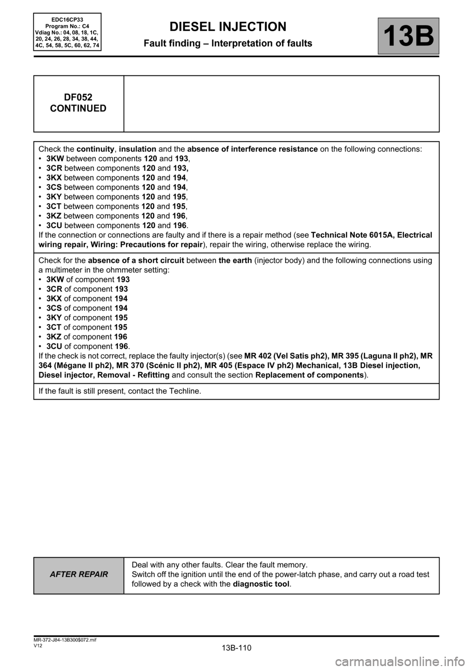
DF052
CONTINUED
Check the continuity, insulation and the absence of interference resistance on the following connections:
•3KW between components 120 and 193,
•3CR between components 120 and 193,
•3KX between components 120 and 194,
•3CS between components 120 and 194,
•3KY between components 120 and 195,
•3CT between components 120 and 195,
•3KZ between components 120 and 196,
•3CU between components 120 and 196.
If the connection or connections are faulty and if there is a repair method (see Technical Note 6015A, Electrical
wiring repair, Wiring: Precautions for repair), repair the wiring, otherwise replace the wiring.
Check for the absence of a short circuit between the earth (injector body) and the following connections using
a multimeter in the ohmmeter setting:
•3KW of component 193
•3CR of component 193
•3KX of component 194
•3CS of component 194
•3KY of component 195
•3CT of component 195
•
3KZ of component 196
•3CU of component 196.
If the check is not correct, replace the faulty injector(s) (see MR 402 (Vel Satis ph2), MR 395 (Laguna II ph2), MR
364 (Mégane II ph2), MR 370 (Scénic II ph2), MR 405 (Espace IV ph2) Mechanical, 13B Diesel injection,
Diesel injector, Removal - Refitting and consult the section Replacement of components).
If the fault is still present, contact the Techline.