Air condition RENAULT SCENIC 2012 J95 / 3.G Engine And Peripherals EDC16CP33 Workshop Manual
[x] Cancel search | Manufacturer: RENAULT, Model Year: 2012, Model line: SCENIC, Model: RENAULT SCENIC 2012 J95 / 3.GPages: 510, PDF Size: 2.98 MB
Page 448 of 510
13B-448V12 MR-372-J84-13B300$150.mif
DIESEL INJECTION
Fault finding – Interpretation of commands13B
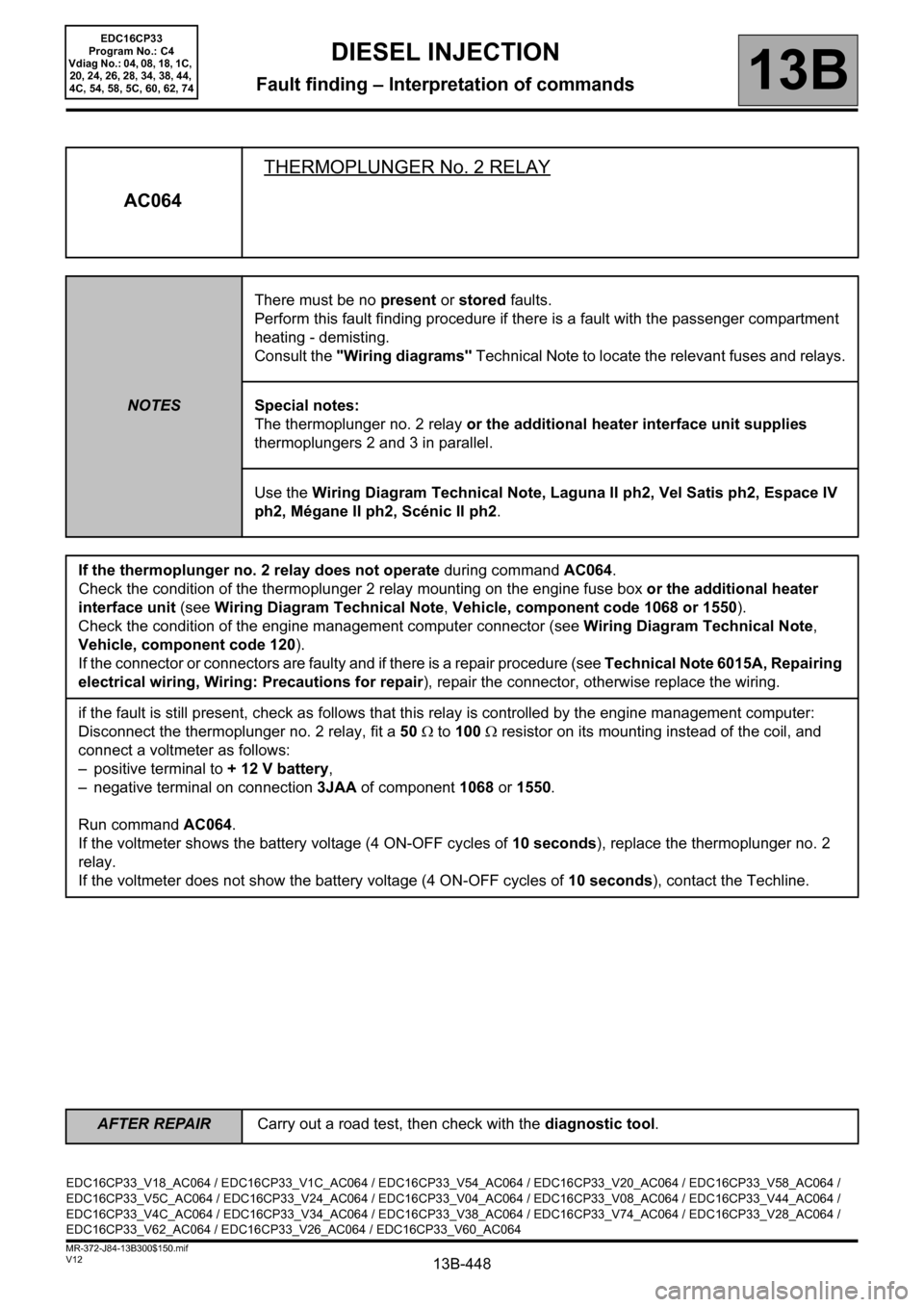
AC064THERMOPLUNGER No. 2 RELAY
NOTESThere must be no present or stored faults.
Perform this fault finding procedure if there is a fault with the passenger compartment
heating - demisting.
Consult the "Wiring diagrams" Technical Note to locate the relevant fuses and relays.
Special notes:
The thermoplunger no. 2 relay or the additional heater interface unit supplies
thermoplungers 2 and 3 in parallel.
Use the Wiring Diagram Technical Note, Laguna II ph2, Vel Satis ph2, Espace IV
ph2, Mégane II ph2, Scénic II ph2.
If the thermoplunger no. 2 relay does not operate during command AC064.
Check the condition of the thermoplunger 2 relay mounting on the engine fuse box or the additional heater
interface unit (see Wiring Diagram Technical Note, Vehicle, component code 1068 or 1550).
Check the condition of the engine management computer connector (see Wiring Diagram Technical Note,
Vehicle, component code 120).
If the connector or connectors are faulty and if there is a repair procedure (see Technical Note 6015A, Repairing
electrical wiring, Wiring: Precautions for repair), repair the connector, otherwise replace the wiring.
if the fault is still present, check as follows that this relay is controlled by the engine management computer:
Disconnect the thermoplunger no. 2 relay, fit a 50 Ω to 100 Ω resistor on its mounting instead of the coil, and
connect a voltmeter as follows:
– positive terminal to + 12 V battery,
– negative terminal on connection 3JAA of component 1068 or 1550.
Run command AC064.
If the voltmeter shows the battery voltage (4 ON-OFF cycles of 10 seconds), replace the thermoplunger no. 2
relay.
If the voltmeter does not show the battery voltage (4 ON-OFF cycles of 10 seconds), contact the Techline.
EDC16CP33_V18_AC064 / EDC16CP33_V1C_AC064 / EDC16CP33_V54_AC064 / EDC16CP33_V20_AC064 / EDC16CP33_V58_AC064 /
EDC16CP33_V5C_AC064 / EDC16CP33_V24_AC064 / EDC16CP33_V04_AC064 / EDC16CP33_V08_AC064 / EDC16CP33_V44_AC064 /
EDC16CP33_V4C_AC064 / EDC16CP33_V34_AC064 / EDC16CP33_V38_AC064 / EDC16CP33_V74_AC064 / EDC16CP33_V28_AC064 /
EDC16CP33_V62_AC064 / EDC16CP33_V26_AC064 / EDC16CP33_V60_AC064
EDC16CP33
Program No.: C4
Vdiag No.: 04, 08, 18, 1C,
20, 24, 26, 28, 34, 38, 44,
4C, 54, 58, 5C, 60, 62, 74
AFTER REPAIRCarry out a road test, then check with the diagnostic tool.
Page 452 of 510
13B-452V12 MR-372-J84-13B300$150.mif
DIESEL INJECTION
Fault finding – Interpretation of commands13B
Laguna II ph2, Vel Satis ph2, Espace IV ph2 only.
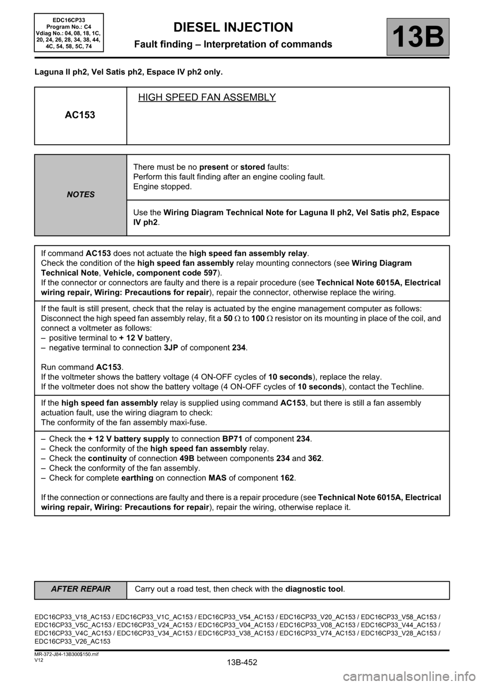
AC153HIGH SPEED FAN ASSEMBLY
NOTESThere must be no present or stored faults:
Perform this fault finding after an engine cooling fault.
Engine stopped.
Use the Wiring Diagram Technical Note for Laguna II ph2, Vel Satis ph2, Espace
IV ph2.
If command AC153 does not actuate the high speed fan assembly relay.
Check the condition of the high speed fan assembly relay mounting connectors (see Wiring Diagram
Technical Note, Vehicle, component code 597).
If the connector or connectors are faulty and there is a repair procedure (see Technical Note 6015A, Electrical
wiring repair, Wiring: Precautions for repair), repair the connector, otherwise replace the wiring.
If the fault is still present, check that the relay is actuated by the engine management computer as follows:
Disconnect the high speed fan assembly relay, fit a 50 Ω to 100 Ω resistor on its mounting in place of the coil, and
connect a voltmeter as follows:
– positive terminal to + 12 V battery,
– negative terminal to connection 3JP of component 234.
Run command AC153.
If the voltmeter shows the battery voltage (4 ON-OFF cycles of 10 seconds), replace the relay.
If the voltmeter does not show the battery voltage (4 ON-OFF cycles of 10 seconds), contact the Techline.
If the high speed fan assembly relay is supplied using command AC153, but there is still a fan assembly
actuation fault, use the wiring diagram to check:
The conformity of the fan assembly maxi-fuse.
– Check the + 12 V battery supply to connection BP71 of component 234.
– Check the conformity of the high speed fan assembly relay.
– Check the continuity of connection 49B between components 234 and 362.
– Check the conformity of the fan assembly.
– Check for complete earthing on connection MAS of component 162.
If the connection or connections are faulty and there is a repair procedure (see Technical Note 6015A, Electrical
wiring repair, Wiring: Precautions for repair), repair the wiring, otherwise replace it.
EDC16CP33_V18_AC153 / EDC16CP33_V1C_AC153 / EDC16CP33_V54_AC153 / EDC16CP33_V20_AC153 / EDC16CP33_V58_AC153 /
EDC16CP33_V5C_AC153 / EDC16CP33_V24_AC153 / EDC16CP33_V04_AC153 / EDC16CP33_V08_AC153 / EDC16CP33_V44_AC153 /
EDC16CP33_V4C_AC153 / EDC16CP33_V34_AC153 / EDC16CP33_V38_AC153 / EDC16CP33_V74_AC153 / EDC16CP33_V28_AC153 /
EDC16CP33_V26_AC153
EDC16CP33
Program No.: C4
Vdiag No.: 04, 08, 18, 1C,
20, 24, 26, 28, 34, 38, 44,
4C, 54, 58, 5C, 74
AFTER REPAIRCarry out a road test, then check with the diagnostic tool.
Page 453 of 510
13B-453V12 MR-372-J84-13B300$150.mif
DIESEL INJECTION
Fault finding – Interpretation of commands13B
Laguna II ph2, Vel Satis ph2, Espace IV ph2 only.
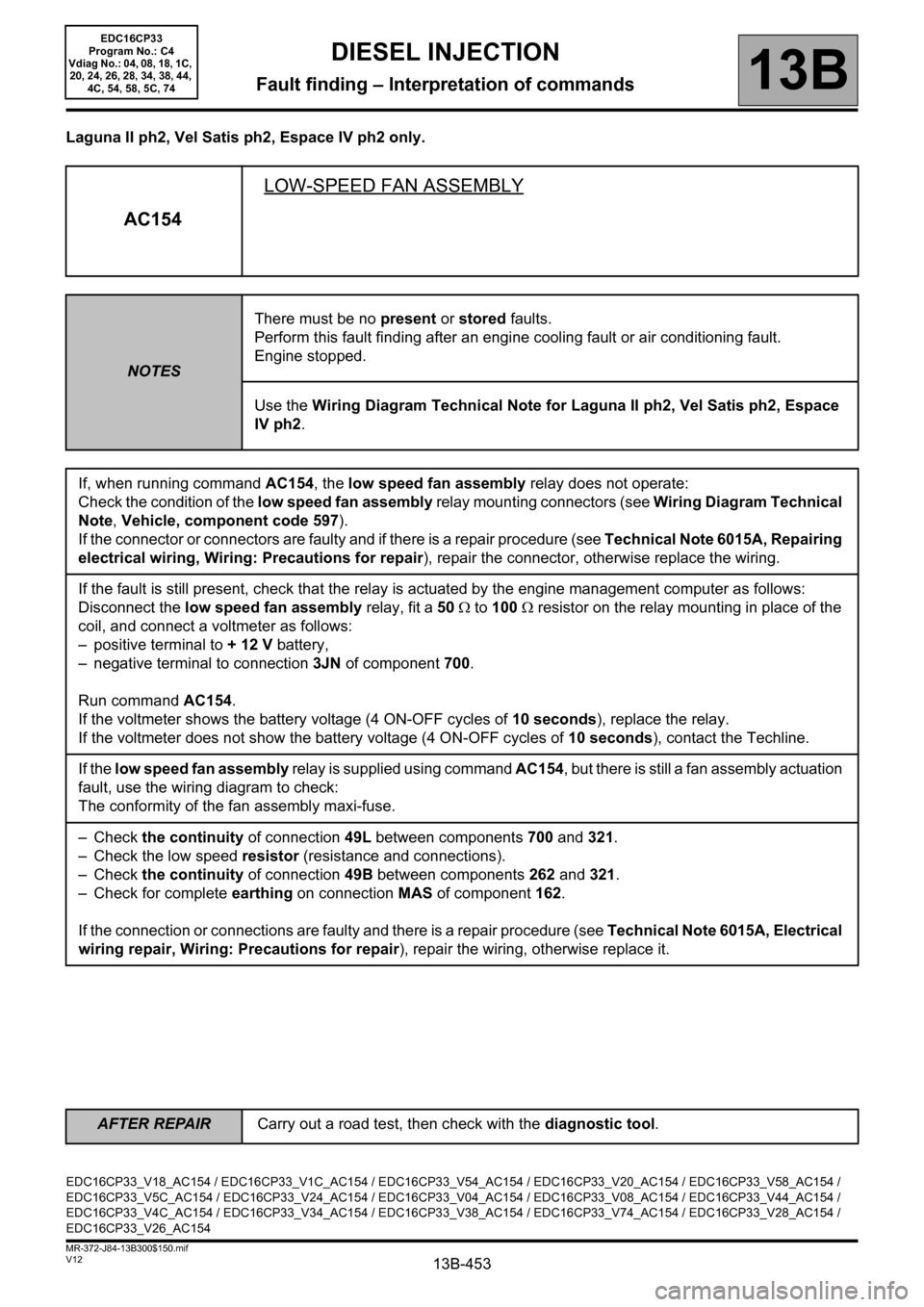
AC154LOW-SPEED FAN ASSEMBLY
NOTESThere must be no present or stored faults.
Perform this fault finding after an engine cooling fault or air conditioning fault.
Engine stopped.
Use the Wiring Diagram Technical Note for Laguna II ph2, Vel Satis ph2, Espace
IV ph2.
If, when running command AC154, the low speed fan assembly relay does not operate:
Check the condition of the low speed fan assembly relay mounting connectors (see Wiring Diagram Technical
Note, Vehicle, component code 597).
If the connector or connectors are faulty and if there is a repair procedure (see Technical Note 6015A, Repairing
electrical wiring, Wiring: Precautions for repair), repair the connector, otherwise replace the wiring.
If the fault is still present, check that the relay is actuated by the engine management computer as follows:
Disconnect the low speed fan assembly relay, fit a 50 Ω to 100 Ω resistor on the relay mounting in place of the
coil, and connect a voltmeter as follows:
– positive terminal to + 12 V battery,
– negative terminal to connection 3JN of component 700.
Run command AC154.
If the voltmeter shows the battery voltage (4 ON-OFF cycles of 10 seconds), replace the relay.
If the voltmeter does not show the battery voltage (4 ON-OFF cycles of 10 seconds), contact the Techline.
If the low speed fan assembly relay is supplied using command AC154, but there is still a fan assembly actuation
fault, use the wiring diagram to check:
The conformity of the fan assembly maxi-fuse.
– Check the continuity of connection 49L between components 700 and 321.
– Check the low speed resistor (resistance and connections).
– Check the continuity of connection 49B between components 262 and 321.
– Check for complete earthing on connection MAS of component 162.
If the connection or connections are faulty and there is a repair procedure (see Technical Note 6015A, Electrical
wiring repair, Wiring: Precautions for repair), repair the wiring, otherwise replace it.
EDC16CP33_V18_AC154 / EDC16CP33_V1C_AC154 / EDC16CP33_V54_AC154 / EDC16CP33_V20_AC154 / EDC16CP33_V58_AC154 /
EDC16CP33_V5C_AC154 / EDC16CP33_V24_AC154 / EDC16CP33_V04_AC154 / EDC16CP33_V08_AC154 / EDC16CP33_V44_AC154 /
EDC16CP33_V4C_AC154 / EDC16CP33_V34_AC154 / EDC16CP33_V38_AC154 / EDC16CP33_V74_AC154 / EDC16CP33_V28_AC154 /
EDC16CP33_V26_AC154
EDC16CP33
Program No.: C4
Vdiag No.: 04, 08, 18, 1C,
20, 24, 26, 28, 34, 38, 44,
4C, 54, 58, 5C, 74
AFTER REPAIRCarry out a road test, then check with the diagnostic tool.
Page 454 of 510

13B-454V12 MR-372-J84-13B300$150.mif
DIESEL INJECTION
Fault finding – Interpretation of commands13B
ac195electric coolant pump
NOTESthis command allows you to check the operation of the electric coolant pump.
Check the connection and condition of the coolant pump relay connector, component code 573 and the injection
computer connector, component code 120.
If the connectors are faulty and if there is a repair procedure (see Technical Note 6015A, Repairing electrical
wiring, Wiring: Precautions for repair), repair the connector, otherwise replace the connector.
Check the insulation, continuity and the absence of interference resistance on the following connections:
•3AAZ between components 573 and 120,
•3VH between components 573 and 369,
•3FB between components 573 and 983,
•3FB1 between components 573 and 983.
If the connection or connections are faulty and there is a repair procedure (see Technical Note 6015A, Electrical
wiring repair, Wiring: Precautions for repair), repair the wiring, otherwise replace it.
If the fault is still present, contact the techline.
EDC16CP33_V18_AC195 / EDC16CP33_V1C_AC195 / EDC16CP33_V54_AC195 / EDC16CP33_V20_AC195 / EDC16CP33_V58_AC195 /
EDC16CP33_V5C_AC195 / EDC16CP33_V24_AC195 / EDC16CP33_V28_AC195 / EDC16CP33_V62_AC195 / EDC16CP33_V26_AC195 /
EDC16CP33_V60_AC195
EEDC16CP33
Program No.: C4
Vdiag No.: 18, 1C, 20, 24,
26, 28, 54, 58, 5C, 60, 62
AFTER REPAIRCarry out a road test, then check with the diagnostic tool.
Page 456 of 510
13B-456V12 MR-372-J84-13B300$150.mif
DIESEL INJECTION
Fault finding – Interpretation of commands13B
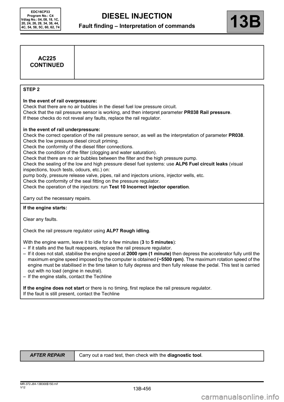
AC225
CONTINUED
STEP 2
In the event of rail overpressure:
Check that there are no air bubbles in the diesel fuel low pressure circuit.
Check that the rail pressure sensor is working, and then interpret parameter PR038 Rail pressure.
If these checks do not reveal any faults, replace the rail regulator.
in the event of rail underpressure:
Check the correct operation of the rail pressure sensor, as well as the interpretation of parameter PR038.
Check the low pressure diesel circuit priming.
Check the conformity of the diesel filter connections.
Check the condition of the filter (clogging and water saturation).
Check that there are no air bubbles between the filter and the high pressure pump.
Check the sealing of the low and high pressure diesel fuel systems: use ALP6 Fuel circuit leaks (visual
inspections, touch tests, odours, etc.) on:
pump body, pressure release valve, pipes, rail and injectors unions, injector wells, etc.
Check the conformity of the seal fitting on the pressure regulator.
Check the operation of the injectors: run Test 10 Incorrect injector operation.
Carry out the necessary repairs.
If the engine starts:
Clear any faults.
Check the rail pressure regulator using ALP7 Rough idling.
With the engine warm, leave it to idle for a few minutes (3 to 5 minutes):
– If it stalls and the fault reappears, replace the rail pressure regulator.
– If it does not stall, stabilise the engine speed at 2000 rpm (1 minute) then depress the accelerator fully until the
maximum engine speed imposed by the computer is obtained (~5500 rpm). The maximum rotation speed of the
engine must be stabilised in the time taken to fully depress and then fully release the pedal. This test is carried
out with no load (engine in neutral).
– If the engine stalls, contact the Techline
If the engine does not start or there is no timing, first replace the rail pressure regulator.
If the fault is still present, contact the Techline
EDC16CP33
Program No.: C4
Vdiag No.: 04, 08, 18, 1C,
20, 24, 26, 28, 34, 38, 44,
4C, 54, 58, 5C, 60, 62, 74
AFTER REPAIRCarry out a road test, then check with the diagnostic tool.
Page 458 of 510
13B-458V12 MR-372-J84-13B300$150.mif
DIESEL INJECTION
Fault finding – Interpretation of commands13B
AC226
CONTINUED
STEP 2
In the event of rail overpressure:
Check that there are no air bubbles in the diesel fuel low pressure circuit.
Check that the rail pressure sensor is working, and then interpret parameter PR038 Rail pressure.
If these checks do not reveal any faults, replace the pump regulator.
in the event of rail underpressure:
Check the correct operation of the rail pressure sensor, as well as the interpretation of parameter PR038.
Check the low pressure diesel circuit priming.
Check the conformity of the diesel filter connections.
Check the condition of the filter (clogging and water saturation).
Check that there are no air bubbles between the filter and the high pressure pump.
Check the sealing of the low and high pressure diesel fuel systems: use ALP6 Fuel circuit leaks (visual
inspections, touch tests, odours, etc.) on:
pump body, pressure release valve, pipes, rail and injectors unions, injector wells, etc.
Check the conformity of the seal fitting on the pressure regulator.
Check the operation of the injectors: run Test 10 Poor injector operation in this document.
Carry out the necessary repairs.
If the engine starts:
Clear any faults.
Check the pump pressure regulator by applying (see ALP 7 Rough idle).
With the engine warm, leave it to idle for a few minutes (3 to 5 minutes):
– If it stalls and the fault reappears, replace the pump regulator.
– If the engine does not stall, stabilise the engine speed at 2000 rpm (1 minute) then depress the accelerator
pedal fully until the maximum engine speed imposed by the computer is obtained (~5500 rpm). The maximum
rotation speed of the engine must be stabilised in the time taken to fully depress and then fully release the pedal.
This test is carried out with no load (engine in neutral).
– If the engine stalls, contact the Techline
If the engine does not start or does not stall, first replace the pump regulator.
If the fault is still present, contact the techline.
EDC16CP33
Program No.: C4
Vdiag No.: 04, 08, 18, 1C,
20, 24, 26, 28, 34, 38, 44,
4C, 54, 58, 5C, 60, 62, 74
AFTER REPAIRCarry out a road test, then check with the diagnostic tool.
Page 460 of 510
13B-460V12 MR-372-J84-13B300$150.mif
DIESEL INJECTION
Fault finding – Interpretation of commands13B
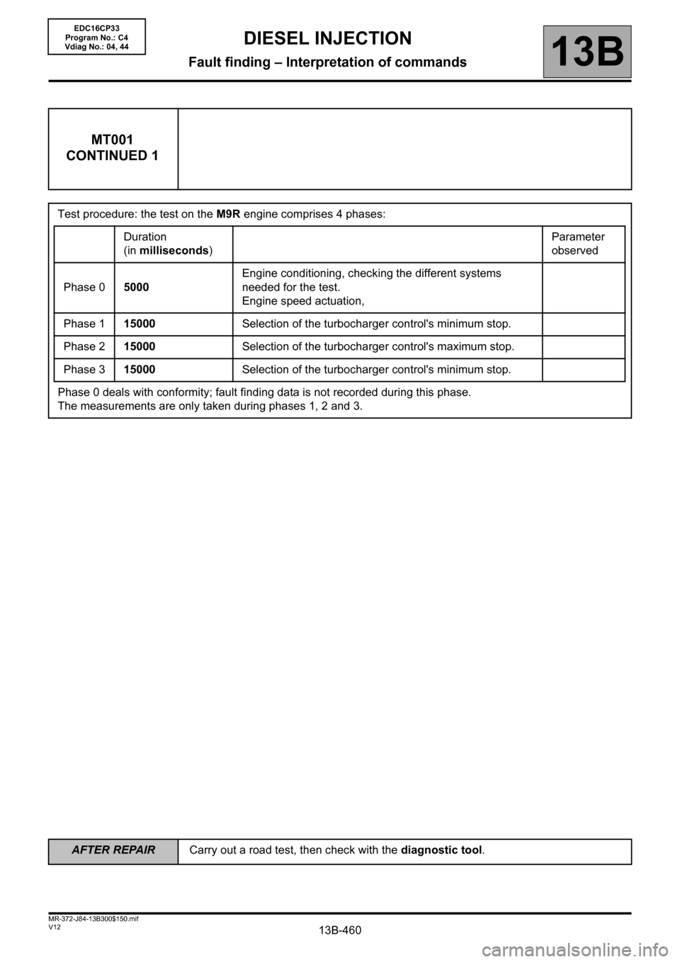
MT001
CONTINUED 1
Test procedure: the test on the M9R engine comprises 4 phases:
Duration
(in milliseconds)Parameter
observed
Phase 05000Engine conditioning, checking the different systems
needed for the test.
Engine speed actuation,
Phase 115000Selection of the turbocharger control's minimum stop.
Phase 215000Selection of the turbocharger control's maximum stop.
Phase 315000Selection of the turbocharger control's minimum stop.
Phase 0 deals with conformity; fault finding data is not recorded during this phase.
The measurements are only taken during phases 1, 2 and 3.
EDC16CP33
Program No.: C4
Vdiag No.: 04, 44
AFTER REPAIRCarry out a road test, then check with the diagnostic tool.
Page 462 of 510
13B-462V12 MR-372-J84-13B300$150.mif
DIESEL INJECTION
Fault finding – Interpretation of commands13B
MT001
CONTINUED 3
Fault finding procedure Monitool no. 1:
– Check the fitting of the air flowmeter (direction of fitting to be observed).
– Check the tightness of the different air flowmeter clips.
– Check the + 5 V supply of connection 3KJ of component 799.
If the connection is faulty and there is a repair procedure (see Technical Note 6015A, Electrical wiring repair,
Wiring: Precautions for repair), repair the wiring, otherwise replace it.
– Check that there are no air leaks between the air flowmeter and the turbocharger.
– Run Test 5 Air flowmeter: check that there is no dust on the sensors.
If the checks do not reveal any non-conformity and the fault is still present, change the air flowmeter. Attach a
screen copy of the Monitool results.
Monitool no. 2 fault finding procedure:
– Measure the internal resistance of the turbocharger control solenoid valve by applying the interpretation of
DF054 Turbocharging solenoid valve control circuit.
– Check the connection of all the air hoses and the tightness of the clips.
– Check the condition of the air filter and replace it if necessary.
– Check that the exhaust pipe is not clogged, run Test 1 Exhaust pipe check.
–Apply Test 7 Variable geometry turbocharger control.
– Check that there are no leaks around the exhaust manifold.
– Check that there is no clogging obstructing the air refrigerant.
– Check that there are no air leaks on the engine (compression test).
If the checks do not reveal any non-conformity and the fault is still present, replace the turbocharger. Attach a
screen copy of the Monitool results.
EDC16CP33
Program No.: C4
Vdiag No.: 04, 44
AFTER REPAIRCarry out a road test, then check with the diagnostic tool.
Page 473 of 510
13B-473
AFTER REPAIRCarry out a road test, then check with the diagnostic tool.
V12 MR-372-J84-13B300$170.mif
DIESEL INJECTION
Fault finding – Fault Finding Chart13B
ALP2
CONTINUED 1
If the connection or connections are faulty and there is a repair procedure (see Technical Note 6015A, Electrical
wiring repair, Wiring: Precautions for repair), repair the wiring, otherwise replace it.
Check the conformity of the engine earths (oxidation, tightness, etc.).
Check the mounting and condition (overheating) of the sensor.
Check the synchronisation of the camshaft sensors and the engine speed sensors with the display of ET238
Synchronisation. If synchronisation is not active, refer to the checks described in DF195 Camshaft/engine
speed sensor consistency.
Test the high pressure fuel circuit:
Run scenario SC035 High pressure fuel circuit fault finding.
To interpret the result, apply the interpretation of command SC035 (see Interpretation of commands).
Check the fuel circuit sealing: run Test 3 Low pressure circuit check.
If Test 3 is correct.
If Test 3 is not correct, proceed as follows:
Check the conformity of the type of heater plugs configured:
For Vdiag 20, 24, 38 and 74: consult ET781 Heater plugs in the Ignition/Preheating subfunction and check the
conformity with the type of plugs installed:
– Slow plugs have a black ring.
– Fast plugs have a white ring.
If the heater plugs are being replaced with plugs of a different type (see Replacement of components, Replacing
heater plugs).
For all Vdiags, check that all 4 plugs have the same colour ring.
Check that the heater plugs are actuated using the AC037 Preheating relay command.
Check the sealing and condition of the inlet circuit: run Test 4 Turbocharged air inlet circuit check, and follow
the related fault finding procedure (see Test 4).
EDC16CP33
Program No.: C4
Vdiag No.: 04, 08, 18, 1C,
20, 24, 26, 28, 34, 38, 44,
4C, 54, 58, 5C, 60, 62, 74
Page 477 of 510
13B-477
AFTER REPAIRCarry out a road test, then check with the diagnostic tool.
V12 MR-372-J84-13B300$170.mif
DIESEL INJECTION
Fault finding – Fault Finding Chart13B
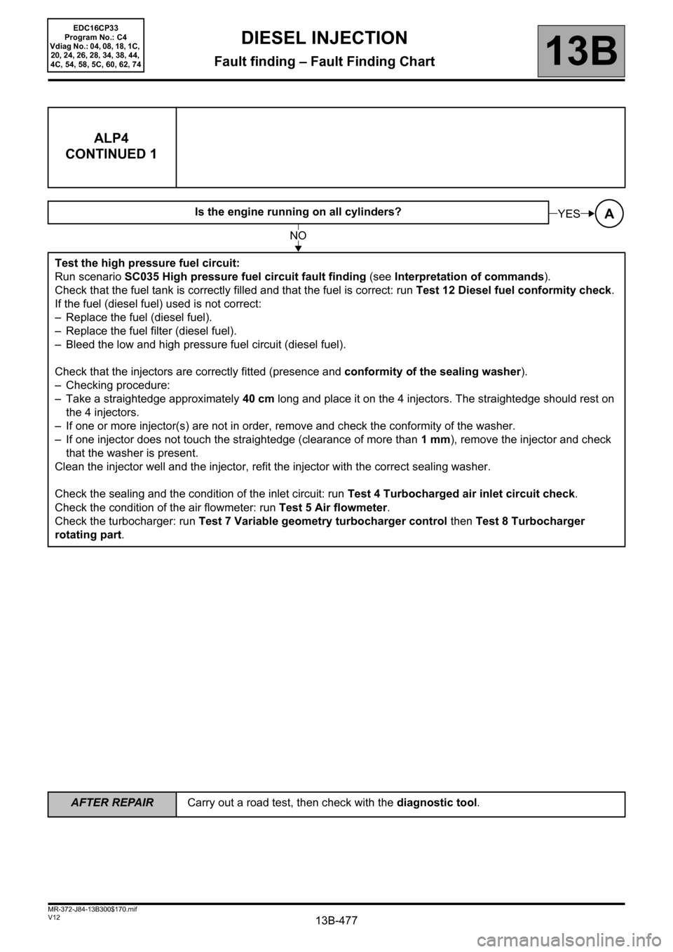
ALP4
CONTINUED 1
Is the engine running on all cylinders?
Test the high pressure fuel circuit:
Run scenario SC035 High pressure fuel circuit fault finding (see Interpretation of commands).
Check that the fuel tank is correctly filled and that the fuel is correct: run Test 12 Diesel fuel conformity check.
If the fuel (diesel fuel) used is not correct:
– Replace the fuel (diesel fuel).
– Replace the fuel filter (diesel fuel).
– Bleed the low and high pressure fuel circuit (diesel fuel).
Check that the injectors are correctly fitted (presence and conformity of the sealing washer).
– Checking procedure:
– Take a straightedge approximately 40 cm long and place it on the 4 injectors. The straightedge should rest on
the 4 injectors.
– If one or more injector(s) are not in order, remove and check the conformity of the washer.
– If one injector does not touch the straightedge (clearance of more than 1mm), remove the injector and check
that the washer is present.
Clean the injector well and the injector, refit the injector with the correct sealing washer.
Check the sealing and the condition of the inlet circuit: run Test 4 Turbocharged air inlet circuit check.
Check the condition of the air flowmeter: run Test 5 Air flowmeter.
Check the turbocharger: run Test 7 Variable geometry turbocharger control then Test 8 Turbocharger
rotating part.AYES
NO
EDC16CP33
Program No.: C4
Vdiag No.: 04, 08, 18, 1C,
20, 24, 26, 28, 34, 38, 44,
4C, 54, 58, 5C, 60, 62, 74