light RENAULT SCENIC 2014 J95 / 3.G Petrol Injection - Sagem3000 Repair Manual
[x] Cancel search | Manufacturer: RENAULT, Model Year: 2014, Model line: SCENIC, Model: RENAULT SCENIC 2014 J95 / 3.GPages: 181
Page 87 of 181
PETROL INJECTION
Fault finding – Interpretation of faults17B
17B - 87V12 MR-372-J84-17B000$405.mif
SAGEM 3000
Program No.: A7
Vdiag No.: 44, 48
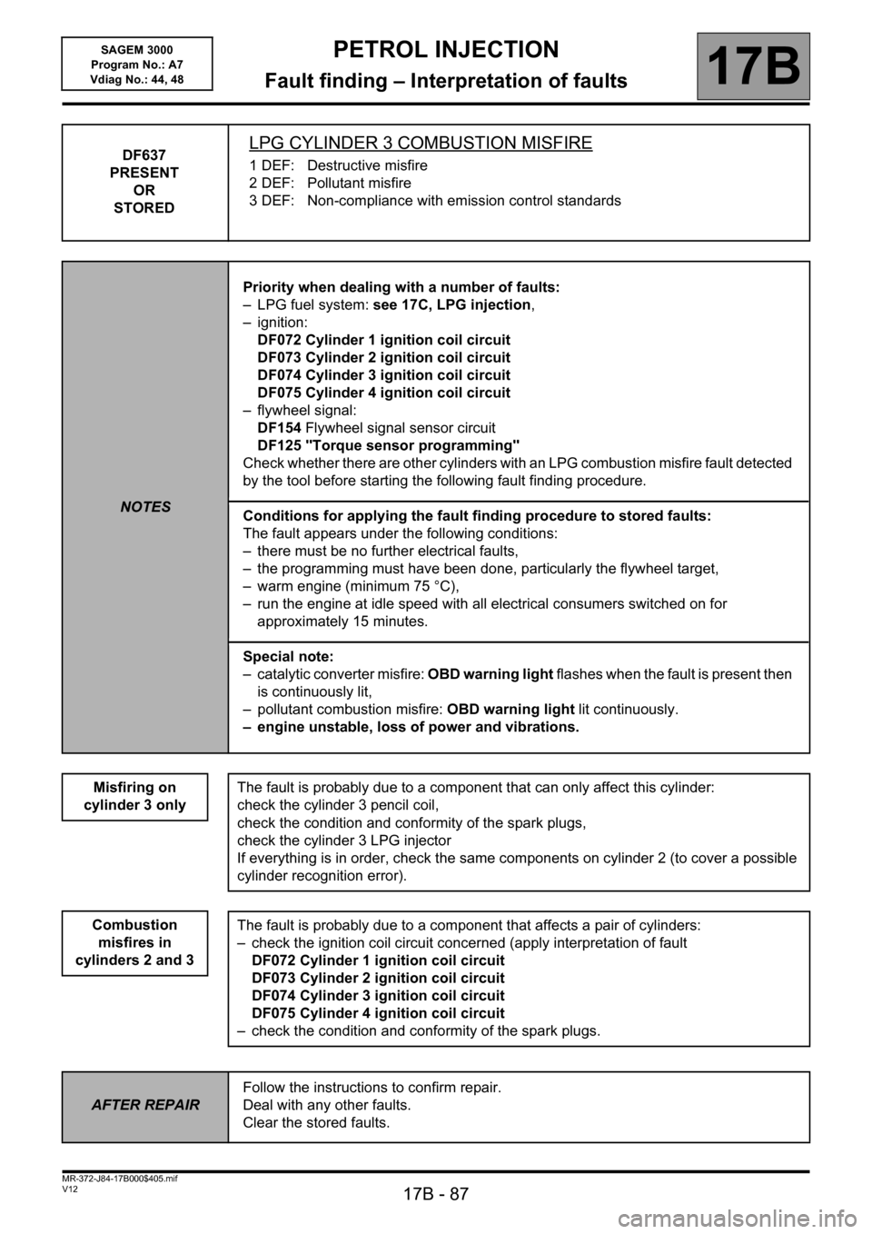
DF637
PRESENT
OR
STOREDLPG CYLINDER 3 COMBUSTION MISFIRE
1 DEF: Destructive misfire
2 DEF: Pollutant misfire
3 DEF: Non-compliance with emission control standards
NOTESPriority when dealing with a number of faults:
– LPG fuel system: see 17C, LPG injection,
– ignition:
DF072 Cylinder 1 ignition coil circuit
DF073 Cylinder 2 ignition coil circuit
DF074 Cylinder 3 ignition coil circuit
DF075 Cylinder 4 ignition coil circuit
– flywheel signal:
DF154 Flywheel signal sensor circuit
DF125 "Torque sensor programming"
Check whether there are other cylinders with an LPG combustion misfire fault detected
by the tool before starting the following fault finding procedure.
Conditions for applying the fault finding procedure to stored faults:
The fault appears under the following conditions:
– there must be no further electrical faults,
– the programming must have been done, particularly the flywheel target,
– warm engine (minimum 75 °C),
– run the engine at idle speed with all electrical consumers switched on for
approximately 15 minutes.
Special note:
– catalytic converter misfire: OBD warning light flashes when the fault is present then
is continuously lit,
– pollutant combustion misfire: OBD warning light lit continuously.
– engine unstable, loss of power and vibrations.
Misfiring on
cylinder 3 only
The fault is probably due to a component that can only affect this cylinder:
check the cylinder 3 pencil coil,
check the condition and conformity of the spark plugs,
check the cylinder 3 LPG injector
If everything is in order, check the same components on cylinder 2 (to cover a possible
cylinder recognition error).
The fault is probably due to a component that affects a pair of cylinders:
– check the ignition coil circuit concerned (apply interpretation of fault
DF072 Cylinder 1 ignition coil circuit
DF073 Cylinder 2 ignition coil circuit
DF074 Cylinder 3 ignition coil circuit
DF075 Cylinder 4 ignition coil circuit
– check the condition and conformity of the spark plugs.
Combustion
misfires in
cylinders 2 and 3
AFTER REPAIRFollow the instructions to confirm repair.
Deal with any other faults.
Clear the stored faults.
Page 88 of 181
PETROL INJECTION
Fault finding – Interpretation of faults17B
17B - 88V12 MR-372-J84-17B000$405.mif
SAGEM 3000
Program No.: A7
Vdiag No.: 44, 48
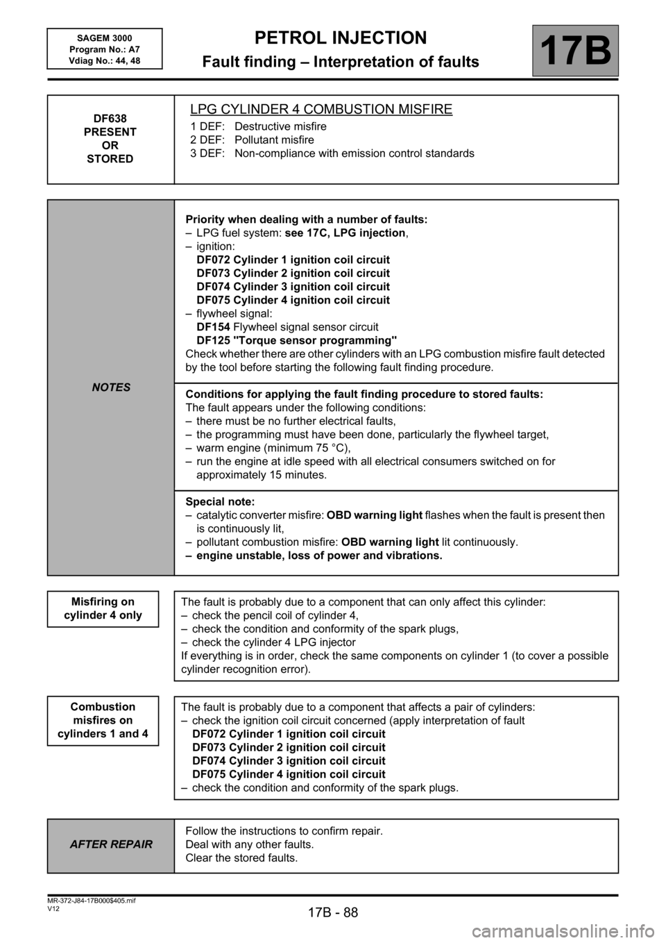
DF638
PRESENT
OR
STOREDLPG CYLINDER 4 COMBUSTION MISFIRE
1 DEF: Destructive misfire
2 DEF: Pollutant misfire
3 DEF: Non-compliance with emission control standards
NOTESPriority when dealing with a number of faults:
– LPG fuel system: see 17C, LPG injection,
– ignition:
DF072 Cylinder 1 ignition coil circuit
DF073 Cylinder 2 ignition coil circuit
DF074 Cylinder 3 ignition coil circuit
DF075 Cylinder 4 ignition coil circuit
– flywheel signal:
DF154 Flywheel signal sensor circuit
DF125 "Torque sensor programming"
Check whether there are other cylinders with an LPG combustion misfire fault detected
by the tool before starting the following fault finding procedure.
Conditions for applying the fault finding procedure to stored faults:
The fault appears under the following conditions:
– there must be no further electrical faults,
– the programming must have been done, particularly the flywheel target,
– warm engine (minimum 75 °C),
– run the engine at idle speed with all electrical consumers switched on for
approximately 15 minutes.
Special note:
– catalytic converter misfire: OBD warning light flashes when the fault is present then
is continuously lit,
– pollutant combustion misfire: OBD warning light lit continuously.
– engine unstable, loss of power and vibrations.
Misfiring on
cylinder 4 only
The fault is probably due to a component that can only affect this cylinder:
– check the pencil coil of cylinder 4,
– check the condition and conformity of the spark plugs,
– check the cylinder 4 LPG injector
If everything is in order, check the same components on cylinder 1 (to cover a possible
cylinder recognition error).
The fault is probably due to a component that affects a pair of cylinders:
– check the ignition coil circuit concerned (apply interpretation of fault
DF072 Cylinder 1 ignition coil circuit
DF073 Cylinder 2 ignition coil circuit
DF074 Cylinder 3 ignition coil circuit
DF075 Cylinder 4 ignition coil circuit
– check the condition and conformity of the spark plugs.
Combustion
misfires on
cylinders 1 and 4
AFTER REPAIRFollow the instructions to confirm repair.
Deal with any other faults.
Clear the stored faults.
Page 89 of 181
PETROL INJECTION
Fault finding – Interpretation of faults17B
17B - 89V12 MR-372-J84-17B000$405.mif
SAGEM 3000
Program No.: A7
Vdiag No.: 44, 48
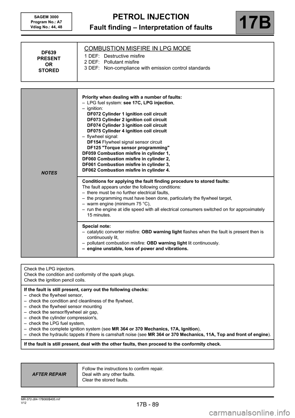
DF639
PRESENT
OR
STOREDCOMBUSTION MISFIRE IN LPG MODE
1 DEF: Destructive misfire
2 DEF: Pollutant misfire
3 DEF: Non-compliance with emission control standards
NOTESPriority when dealing with a number of faults:
– LPG fuel system: see 17C, LPG injection,
– ignition:
DF072 Cylinder 1 ignition coil circuit
DF073 Cylinder 2 ignition coil circuit
DF074 Cylinder 3 ignition coil circuit
DF075 Cylinder 4 ignition coil circuit
– flywheel signal:
DF154 Flywheel signal sensor circuit
DF125 "Torque sensor programming"
DF059 Combustion misfire in cylinder 1,
DF060 Combustion misfire in cylinder 2,
DF061 Combustion misfire in cylinder 3,
DF062 Combustion misfire in cylinder 4.
Conditions for applying the fault finding procedure to stored faults:
The fault appears under the following conditions:
– there must be no further electrical faults,
– the programming must have been done, particularly the flywheel target,
– warm engine (minimum 75 °C),
– run the engine at idle speed with all electrical consumers switched on for approximately
15 minutes.
Special note:
– catalytic converter misfire: OBD warning light flashes when the fault is present then is
continuously lit,
– pollutant combustion misfire: OBD warning light lit continuously.
– engine unstable, loss of power and vibrations.
Check the LPG injectors.
Check the condition and conformity of the spark plugs.
Check the ignition pencil coils.
If the fault is still present, carry out the following checks:
– check the flywheel sensor,
– check the condition and cleanliness of the flywheel,
– check the flywheel sensor mounting
– check the sensor/flywheel air gap,
– check the cylinder compression's,
– check the LPG fuel system,
– check the complete ignition system (see MR 364 or 370 Mechanics, 17A, Ignition),
– check the hydraulic tappets if there is camshaft noise (see MR 364 or 370 Mechanics, 11A, Top and front of engine).
If the fault is still present, deal with the other faults, then proceed to the conformity check.
AFTER REPAIRFollow the instructions to confirm repair.
Deal with any other faults.
Clear the stored faults.
Page 91 of 181

PETROL INJECTION
Fault finding – Conformity check17B
17B-91V12 MR-372-J84-17B000$450.mif
SAGEM 3000
Program No.: A7
Vdiag No.: 44, 48
MAIN COMPUTER STATUSES AND PARAMETERS (continued)
Order FunctionParameter or Status
Checked or ActionDisplay and notes Fault finding
6Brake
contactET039: Brake pedalIndicates recognition of
brake pedal contacts.
RELEASED: Pedal released
DEPRESSED: Pedal
depressedIf there is a fault, use the
interpretation for ET039
Brake pedal.
7 Automatic
gearbox
connectionET063: Park/Neutral
positionAT only.
YES: Automatic transmission
is in parking/neutral position
NO: Automatic transmission
is not in parking/neutral
positionIf ET014 is inconsistent,
perform a multiplex
network test using the
diagnostic tool, then if
the test is in order, see
the gearbox computer.
8
FaultsET064: Level 1
injection faultYES: fault present
NO: fault absentWITHOUT
9 ET065: Level 2
Injection faultYES: fault present
NO: fault absent
WITHOUT 10 PR105: OBD fault
warning light
lit mileage
counterShows distance travelled
with warning light on
11 PR106: Mileage
counter fault
warning
light litShows distance travelled
with warning light on
JSAA741.0
Page 112 of 181

PETROL INJECTION
Fault finding – Conformity check17B
17B-112V12 MR-372-J84-17B000$450.mif
SAGEM 3000
Program No.: A7
Vdiag No.: 44, 48
MAIN COMPUTER STATUSES AND PARAMETERS (continued)
Order FunctionParameter or Status
Checked or ActionDisplay and notes Fault finding
7 Automatic
gearbox
connectionET063: Park/Neutral
positionAT only.
YES: Automatic transmission
is in parking/neutral position
NO: Automatic transmission
is not in parking/neutral
positionIf ET063 is
inconsistent, carry
out a multiplex
network test using
the diagnostic tool. If
the test is correct
check the automatic
transmission.
8
FaultsET064: Level 1 injection
faultYES: fault present
NO: fault absent
WITHOUT 9 ET065: Level 2 Injection
faultYES: fault present
NO: fault absent
10 PR105: OBD fault warning
light lit mileage
counterShows the distance
covered with the warning
light lit.
11 PR106: Mileage counter
fault warning
light litShows the distance
covered with the warning
light lit.
JSAA741.0
Page 133 of 181

PETROL INJECTION
Fault finding – Status summary table17B
17B - 133V12 MR-372-J84-17B000$540.mif
SAGEM 3000
Program No.: A7
Vdiag No.: 44, 48
*AT: automatic transmission
*RCH: passenger compartment heating resistorTool Status Diagnostic tool title
ET074OBD warning light lit by AT*
ET075Pedal released and throttle closed
ET076Starting
ET077Impact detected
ET079Air conditioning present
ET081Accelerator pedal position
ET082Motorised throttle position
ET083Camshaft dephaser in defect mode
ET084Camshaft dephaser
ET086Camshaft dephaser control
ET088Compressor actuation request
ET089Flywheel target programming
ET111RCH* number set
ET112RCH* cut-off
ET405Clutch pedal switch
ET415Deactivation of cruise control/speed limiter
ET542Oil vapour defreeze resistor
ET543Coolant pump control
ET564Type 1 defect mode
ET565Type 2 defect mode
ET566Type 3 defect mode
ET567Type 4 defect mode
ET568Type 5 defect mode
ET569Type 6 defect mode
ET582LPG combustion misfire fault finding
ET703Cruise control/speed limiter buttons
ET704Brake switch No. 1
ET705Brake switch No. 2
JSAA741.0
Page 155 of 181
PETROL INJECTION
Fault finding – Interpretation of statuses17B
17B - 155V12 MR-372-J84-17B000$540.mif
SAGEM 3000
Program No.: A7
Vdiag No.: 44, 48
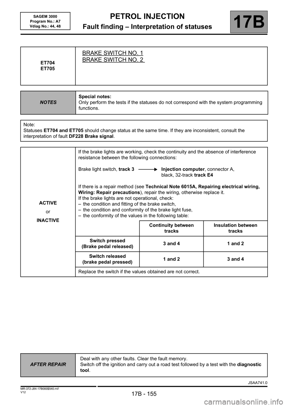
ET704
ET705
BRAKE SWITCH NO. 1
BRAKE SWITCH NO. 2
NOTESSpecial notes:
Only perform the tests if the statuses do not correspond with the system programming
functions.
Note:
Statuses ET704 and ET705 should change status at the same time. If they are inconsistent, consult the
interpretation of fault DF228 Brake signal.
ACTIVE
or
INACTIVEIf the brake lights are working, check the continuity and the absence of interference
resistance between the following connections:
Brake light switch, track 3 Injection computer, connector A,
black, 32-track track E4
If there is a repair method (see Technical Note 6015A, Repairing electrical wiring,
Wiring: Repair precautions), repair the wiring, otherwise replace it.
If the brake lights are not operational, check:
– the condition and fitting of the brake switch,
– the condition and conformity of the brake light fuse,
– the conformity of the values in the following table:
Continuity between
tracksInsulation between
tracks
Switch pressed
(Brake pedal released)3 and 4 1 and 2
Switch released
(brake pedal pressed)1 and 2 3 and 4
Replace the switch if the values obtained are not correct.
AFTER REPAIRDeal with any other faults. Clear the fault memory.
Switch off the ignition and carry out a road test followed by a test with the diagnostic
tool.
1JSAA741.0
Page 157 of 181

PETROL INJECTION
Fault finding – Parameter summary table17B
17B - 157V12 MR-372-J84-17B000$630.mif
SAGEM 3000
Program No.: A7
Vdiag No.: 44, 48
*OCR: Opening cycle ratio
*AT: automatic transmission
*SV: Solenoid valveTool parameter Diagnostic tool title
PR103Instantaneous fuel consumption
PR105OBD fault warning light lit mileage counter
PR106Mileage counter fault warning light lit
PR111Motorised throttle position corrected value.
PR112No load programmed value
PR113Lower throttle stop after applying offset
PR116Motorised throttle corrected position setpoint
PR118Measured throttle position gang 1
PR119Measured throttle position gang 2
PR122Torque received by AT* converter
PR123Estimated driver demand engine torque
PR124Resistant engine torque transmitted via multiplex line
PR125Power absorbed by the air conditioning compressor
PR127Heating resistor max. authorised power
PR130Cruise control setpoint.
PR138Richness correction
PR141Integral idling speed regulation correction
PR143Self-adapting richness gain
PR144Self-adapting richness offset
PR846Turbocharging solenoid valve opening cycle ratio
JSAA741.0
Page 176 of 181
PETROL INJECTION
Fault finding – Fault Finding Chart17B
17B - 176V12 MR-372-J84-17B000$900.mif
SAGEM 3000
Program No.: A7
Vdiag No.: 44, 48PETROL INJECTION
Fault finding – Fault Finding Chart
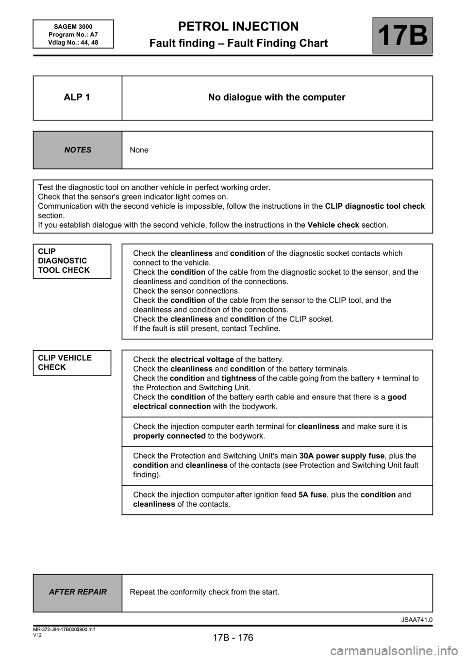
ALP 1 No dialogue with the computer
NOTESNone
Test the diagnostic tool on another vehicle in perfect working order.
Check that the sensor's green indicator light comes on.
Communication with the second vehicle is impossible, follow the instructions in the CLIP diagnostic tool check
section.
If you establish dialogue with the second vehicle, follow the instructions in the Vehicle check section.
CLIP
DIAGNOSTIC
TOOL CHECK
CLIP VEHICLE
CHECK
Check the cleanliness and condition of the diagnostic socket contacts which
connect to the vehicle.
Check the condition of the cable from the diagnostic socket to the sensor, and the
cleanliness and condition of the connections.
Check the sensor connections.
Check the condition of the cable from the sensor to the CLIP tool, and the
cleanliness and condition of the connections.
Check the cleanliness and condition of the CLIP socket.
If the fault is still present, contact Techline.
Check the electrical voltage of the battery.
Check the cleanliness and condition of the battery terminals.
Check the condition and tightness of the cable going from the battery + terminal to
the Protection and Switching Unit.
Check the condition of the battery earth cable and ensure that there is a good
electrical connection with the bodywork.
Check the injection computer earth terminal for cleanliness and make sure it is
properly connected to the bodywork.
Check the Protection and Switching Unit's main 30A power supply fuse, plus the
condition and cleanliness of the contacts (see Protection and Switching Unit fault
finding).
Check the injection computer after ignition feed 5A fuse, plus the condition and
cleanliness of the contacts.
AFTER REPAIRRepeat the conformity check from the start.
JSAA741.0
MR-372-J84-17B000$900.mif