RENAULT TWINGO 2009 2.G Chasiss User Guide
TWINGO 2009 2.G
RENAULT
RENAULT
https://www.carmanualsonline.info/img/7/1719/w960_1719-0.png
RENAULT TWINGO 2009 2.G Chasiss User Guide
Page 18 of 281
30A-14
GENERAL INFORMATION
Rigid brake pipe: Repair
30A
aFit the pipe in the rivet press (see Garage Equip-
ment Catalogue).
aAdjust the length of the pipe to be shaped.
aTorque tighten the press end piece(40 N.m).
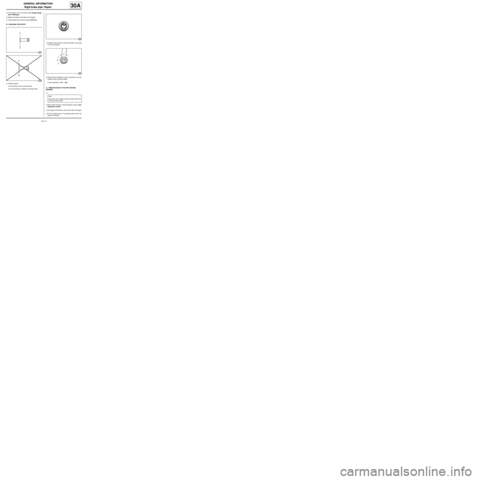
III - CHECKING THE RIVETS
aVisually inspect:
-the uniformity of the rivets' diameter,
-the rivet centring in relation to the pipe shaft.aVisually check that the internal diameter of the pipe
is not oval-shaped.
aCheck that the diameter of the end panel is not oval
shaped using a sliding calliper.
Correct diameter if (X1) = (X2)
IV - PREPARATION OF THE PIPE BEFORE
BENDING
a
aBlow inside the pipe in both directions using a com-
pressed air nozzle.
aPut plugs on the bolts or nuts at the ends of the pipe.
aPut the original pipe on a flat base plate that is the
length of the pipe.
128667
128669
128668
128645
Note:
Impurities may spread inside the pipe while the
rivets are being made.
Page 21 of 281
30A-17
GENERAL INFORMATION
Rigid brake pipe: Repair
30A
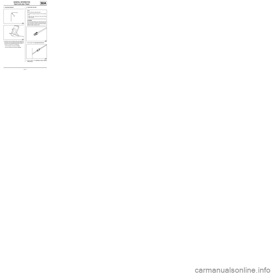
V - CHECKING BENDING
aCheck the out-of-roundness of the outer diameter at
the centre of the curve radius (2) using a sliding cal-
liper (the out-of-roundness of the outer diameter is
correct if it is less than 10% flattening):
-nominal diameter of the pipe: 4.75 mm,
-minimum diameter after bending: 4.30 mm.VI - REFITTING THE PIPE
a
aTorque tighten the brake pipe bolts (8 N.m).
aTorque tighten the underbody unions (female/
male) (6 N.m).
128664
128670
Note:
When refitting the rigid brake pipe:
-respect the original routing as much as possi-
ble,
-adjust the pipe routing by hand when fitting
inside the clips.
WARNING
Contact points between the rigid brake pipe and
the surrounding components could cause dam-
age to the pipe. In order to avoid these contacts,
adjust the pipe routing by hand.
128644
128646
Page 24 of 281
30A-20
GENERAL INFORMATION
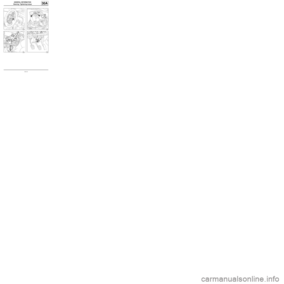
Steering: Tightening torque
30A
119483
119647119883
119544
Page 25 of 281
30A-21
GENERAL INFORMATION
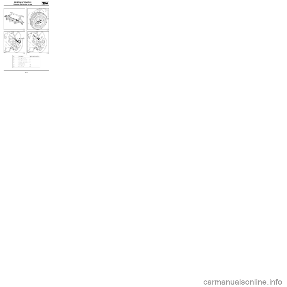
Steering: Tightening torque
30A
119405
121365119649
121364
No. Description Tightening torque (Nm)
(1) Steering wheel bolt 44
(2) Steering column nuts 21
(3) Universal joint bolts on
the steering box24
(4) Steering box bolt 105
(5) Track rod nuts 37
Page 26 of 281
30A-22
GENERAL INFORMATION
Steering: Tightening torque
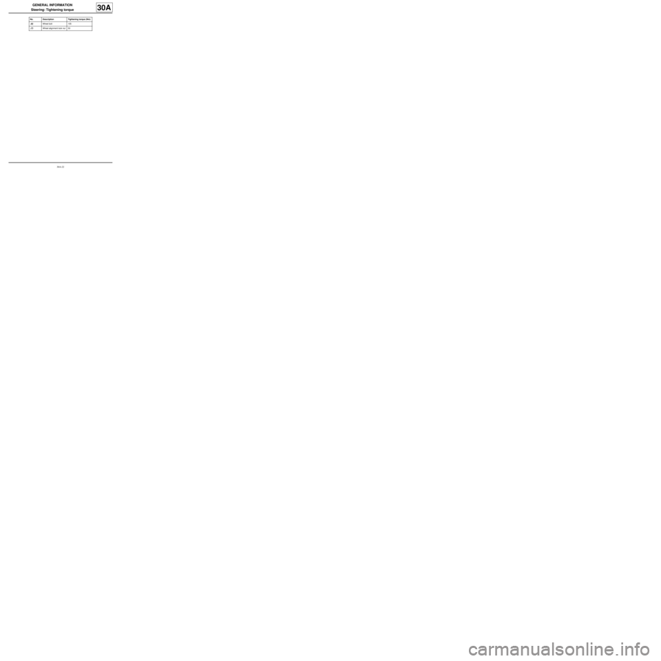
30A
(6) Wheel bolt 105
(7) Wheel alignment lock nut 53 No. Description Tightening torque (Nm)
Page 31 of 281
30A-27
GENERAL INFORMATION
Front axle system: Tightening torque
30A
119335
119210
119336
119406
Page 32 of 281
30A-28
GENERAL INFORMATION
Front axle system: Tightening torque
30A
119224
119344
119654
119221
Page 33 of 281
30A-29
GENERAL INFORMATION
Front axle system: Tightening torque
30A
119543
119405121365
121364
Page 34 of 281
30A-30
GENERAL INFORMATION
Front axle system: Tightening torque
30A
119649
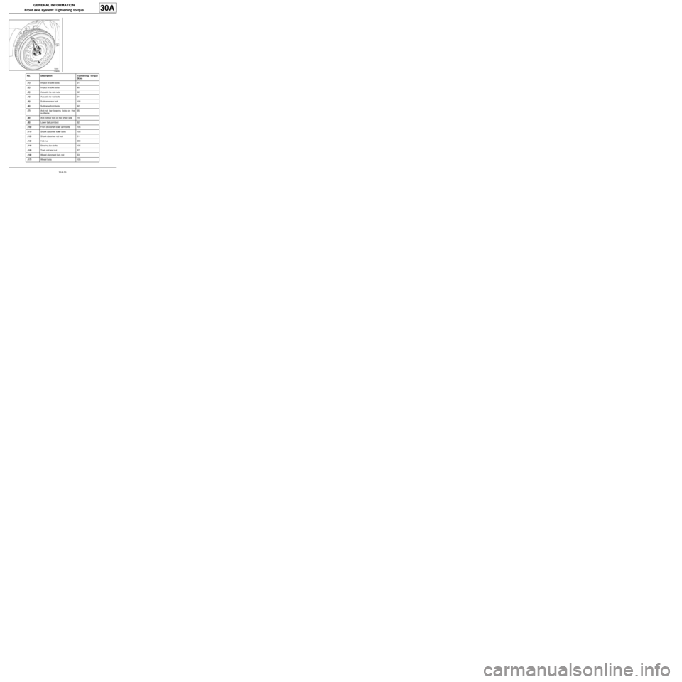
No. DescriptionTightening torque
(N.m)
(1) Impact bracket bolts 21
(2) Impact bracket bolts 90
(3) Acoustic tie-rod nuts 62
(4) Acoustic tie-rod bolts 21
(5) Subframe rear bolt 105
(6) Subframe front bolts 62
(7) Anti-roll bar bearing bolts on the
subframe35
(8) Anti-roll bar bolt on the wheel side 14
(9) Lower ball joint bolt 62
(10) Front driveshaft lower arm bolts 105
(11) Shock absorber lower bolts 105
(12) Shock absorber rod nut 21
(13) Hub nut 280
(14) Steering box bolts 105
(15) Track rod end nut 37
(16) Wheel alignment lock nut 53
(17) Wheel bolts 105
Page 40 of 281
30A-36
GENERAL INFORMATION
Front axle system: Adjustment
30A
I - ADJUSTMENT PREPARATION STAGE
aCheck the geometry (see 30A, General informa-
tion, Axle assemblies: Check, page 30A-23) .
II - ADJUSTMENT OPERATION
1 - Wheel alignment
aSet the wheels straight ahead.
aLock the steering wheel using a flywheel immobil-
iser.
aAdjust the wheel alignment by rotating the track rod
sleeves.
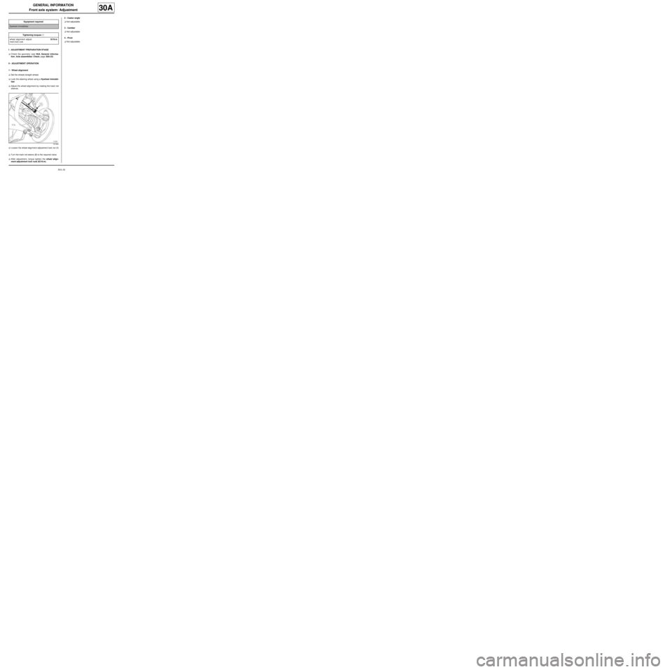
aLoosen the wheel alignment adjustment lock nut (1)
.
aTurn the track rod sleeve (2) to the required value.
aAfter adjustment, torque tighten the wheel align-
ment adjustment lock nuts (53 N.m).2 - Castor angle
aNot adjustable.
3 - Camber
aNot adjustable.
4 - Pivot
aNot adjustable. Equipment required
flywheel immobiliser
Tightening torquesm
wheel alignment adjust-
ment lock nuts53 N.m
121364
