torque RENAULT TWINGO 2009 2.G Chasiss Service Manual
[x] Cancel search | Manufacturer: RENAULT, Model Year: 2009, Model line: TWINGO, Model: RENAULT TWINGO 2009 2.GPages: 281
Page 76 of 281
31A-33
FRONT AXLE COMPONENTS
Front driveshaft lower arm: Removal - Refitting
EQ UIPMENT LEVEL EA0 or EQUIPMENT LEVEL EA1 or EQUIPMENT LEVEL EA3 or EQUIPMENT LEVEL EA5
or EQUIPMENT LEVEL EAG or EQUIPMENT LEVEL EZ2 or EQUIPMENT LEVEL EZ4
31A
REMOVAL
I - REMOVAL PREPARATION OPERATION
aPosition the vehicle on a two-post lift (see Vehicle:
Towing and lifting) (02A, Lifting equipment).
aRemove the front wheel on the side concerned (see
35A, Wheels and tyres, Wheel: Removal - Refit-
ting, page 35A-1) .aCompress the anti-roll bar rubber mounting bush on
the wheel side using the (Sus. 1413) (1) .
aRemove:
-the bolt (2) from the anti-roll bar on the wheel side,
-the rubber mounting bush from the anti-roll bar on
the wheel side. Special tooling required
Sus. 1413Rubber mounting compres-
sor for fitting the anti-roll bar.
(wheel end).
Tightening torquesm
front driveshaft lower
arm bolts105 Nm
lower ball joint bolt105 Nm
acoustic tie-rod nut62 Nm
acoustic tie-rod bolt21 Nm
anti-roll bar bolt on the
wheel side14 Nm
119346
Page 78 of 281
31A-35
FRONT AXLE COMPONENTS
Front driveshaft lower arm: Removal - Refitting
EQ UIPMENT LEVEL EA0 or EQUIPMENT LEVEL EA1 or EQUIPMENT LEVEL EA3 or EQUIPMENT LEVEL EA5
or EQUIPMENT LEVEL EAG or EQUIPMENT LEVEL EZ2 or EQUIPMENT LEVEL EZ4
31A
II - OPERATION FOR REMOVAL OF PART
CONCERNED
aRemove:
-the bolts (7) from the front driveshaft lower arm,
-the front driveshaft lower arm.REFITTING
I - REFITTING OPERATION FOR PART
CONCERNED
aRefit:
-the front driveshaft lower arm,
-the front driveshaft lower arm bolts.
aTorque tighten the front driveshaft lower arm
bolts (105 Nm).
II - FINAL OPERATION.
aFit the lower ball joint on the front driveshaft hub car-
rier.
119344
WARNING
To prevent any damage, do not use the lower
arm as support for the lifting system.
119344
Note:
Obser ve the direction of fitting for the front drive-
shaft lo wer arm bolts (7) .
Page 79 of 281
31A-36
FRONT AXLE COMPONENTS
Front driveshaft lower arm: Removal - Refitting
EQ UIPMENT LEVEL EA0 or EQUIPMENT LEVEL EA1 or EQUIPMENT LEVEL EA3 or EQUIPMENT LEVEL EA5
or EQUIPMENT LEVEL EAG or EQUIPMENT LEVEL EZ2 or EQUIPMENT LEVEL EZ4
31A
aEnsure that the ring (8) is correctly positioned on the
lower ball joint.
aRefit the lower ball joint stud.
aTorque tighten the lower ball joint bolt (105 Nm).
aRefit:
-the acoustic tie-rod,
-the acoustic tie-rod nut,
-the acoustic tie-rod bolt.
aTighten to torque:
-the acoustic tie-rod nut (62 Nm),
-the acoustic tie-rod bolt (21 Nm).
aRefit:
-the anti-roll bar rubber mounting bush on the wheel
side,
-the anti-roll bar bolt on the wheel side.
aCompress the anti-roll bar rubber mounting bush on
the wheel side using the (Sus. 1413).
aRefit the anti-roll bar nut on the wheel side.
aTorque tighten the anti-roll bar bolt on the wheel
side (14 Nm).
aRefit the front wheel on the side concerned (see
35A, Wheels and tyres, Wheel: Removal - Refit-
ting, page 35A-1) .
aCheck the front axle geometry (see 30A, General
information, Front axle assembly: Adjustment
values, page 30A-31) .
119223
Page 80 of 281
31A-37
FRONT AXLE COMPONENTS
Front driveshaft lower arm: Removal - Refitting
EQ UIPMENT LEVEL SPORT
31A
REMOVAL
I - REMOVAL PREPARATION OPERATION
aPosition the vehicle on a two-post lift (see Vehicle:
Towing and lifting) (02A, Lifting equipment).
aRemove the front wheel (see 35A, Wheels and ty-
res, Wheel: Removal - Refitting, page 35A-1) .
aDetach the wheel arch liner (1) .aRemove:
-the bolt (2) from the acoustic tie-rod,
-the nut (3) from the acoustic tie-rod,
-the acoustic tie-rod. Tightening torquesm
front driveshaft lower
arm bolts105 N.m
lower ball joint nut62 N.m
acoustic tie-rod nut62 N.m
acoustic tie-rod bolt21 N.m
119209
119210
Page 82 of 281
31A-39
FRONT AXLE COMPONENTS
Front driveshaft lower arm: Removal - Refitting
EQ UIPMENT LEVEL SPORT
31A
REFITTING
I - REFITTING OPERATION FOR PART
CONCERNED
aRefit the front driveshaft lower arm.
aFit the lower ball joint on the front driveshaft hub car-
rier.
aTorque tighten the front driveshaft lower arm
bolts (105 N.m ).
aTorque tighten the lower ball joint nut (62 N.m).
II - FINAL OPERATION
aRefit the acoustic tie-rod.
aTorque tighten:
-the acoustic tie-rod nut (62 N.m),
-the acoustic tie-rod bolt (21 N.m).
aRefit the front wheel (see 35A, Wheels and tyres,
Wheel: Removal - Refitting, page 35A-1) .
aCheck the front axle geometry (see 30A, General
information, Front axle assembly: Adjustment
values, page 30A-31) .
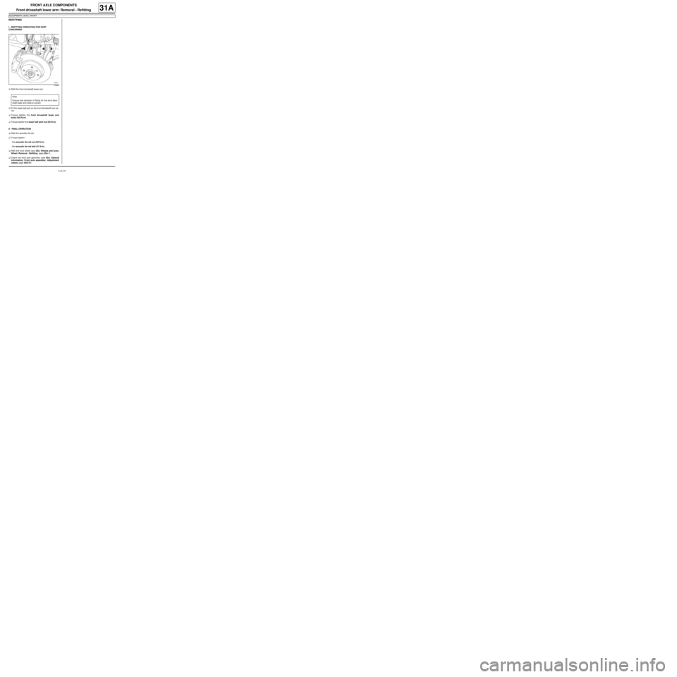
119344
Note:
Ensure that direction of fitting for the front drive-
shaft lower arm bolts is correct.
Page 83 of 281
31A-40
FRONT AXLE COMPONENTS
Front driveshaft lower arm ball joint: Removal - Refitting31A
REMOVAL
I - REMOVAL PREPARATION OPERATION
aPosition the vehicle on a two-post lift (see Vehicle:
Towing and lifting) (MR 411, 02A, Lifting equip-
ment).
aRemove the front wheel on the side concerned (see
35A, Wheels and tyres, Wheel: Removal - Refit-
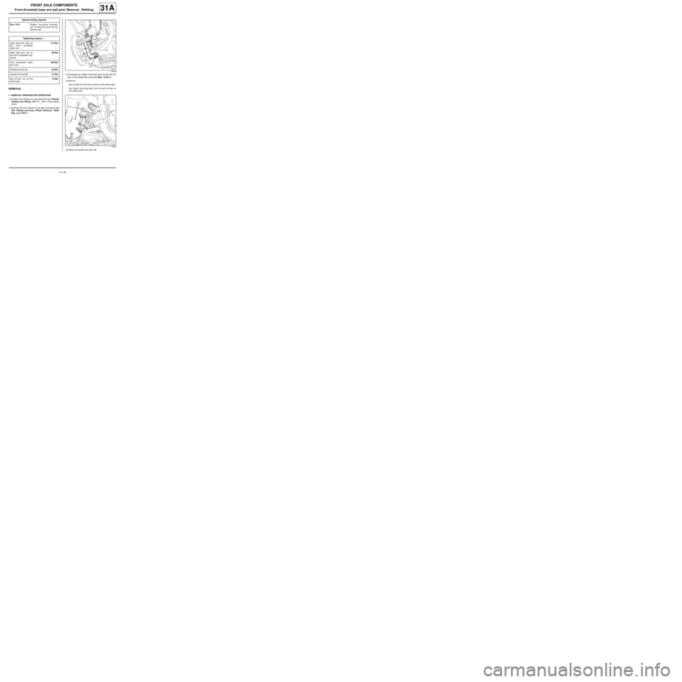
ting, page 35A-1) .aCompress the rubber mounting bush on the anti-roll
bar on the wheel side using the (Sus. 1413) (1) .
aRemove:
-the nut (2) from the anti-roll bar on the wheel side,
-the rubber mounting bush from the anti-roll bar on
the wheel side.
aDetach the wheel arch liner (3) . Special tooling required
Sus. 1413Rubber mounting compres-
sor for fitting the anti-roll bar.
(wheel end).
Tightening torquesm
lower ball joint nuts on
the front driveshaft
lower arm113 Nm
lower ball joint nut on
the front dr iveshaft hub-
carr ier62 Nm
front driveshaft lower
arm nuts105 Nm
acoustic tie-rod nut62 Nm
acoustic tie-rod bolt21 Nm
anti-roll bar nut on the
wheel side14 Nm
119346
119209
Page 85 of 281
31A-42
FRONT AXLE COMPONENTS
Front driveshaft lower arm ball joint: Removal - Refitting31A
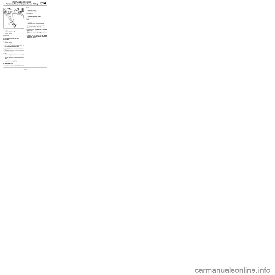
aRemove:
-the lower ball joint nuts (8) ,
-the lower ball joint.
REFITTING
I - REFITTING OPERATION FOR PART
CONCERNED
aRefit:
-the lower ball joint,
-the lower ball joint nuts.
aTorque tighten the lower ball joint nuts on the
front driveshaft lower arm (113 Nm).
aFit the lower ball joint on the front driveshaft hub car-
rier.
aCheck that the plastic ring is correctly positioned on
the lower arm ball joint.
aRefit:
-the lower ball joint bolt on the front driveshaft hub
carrier,
-the lower ball joint nut on the front driveshaft hub-
carrier.
aTorque tighten the lower ball joint nut on the front
driveshaft hub-carrier (62 Nm).
II - FINAL OPERATION.
aTorque tighten the front driveshaft lower arm nuts
(105 Nm).aRefit:
-the acoustic tie-rod,
-the acoustic tie-rod nut,
-the acoustic tie-rod bolt.
aTorque tighten:
-the acoustic tie-rod nut (62 Nm),
-the acoustic tie-rod bolt (21 Nm).
aAttach the wheel arch liner.
aRefit:
-the front anti-roll bar rubber mounting bush on the
wheel side,
-the front anti-roll bar bolt on the wheel side.
aCompress the anti-roll bar rubber mounting bush on
the wheel side using the (Sus. 1413).
aRefit the front anti-roll bar nut on the wheel side.
aTorque tighten the anti-roll bar nut on the wheel
side ( 14 Nm).
aRefit the front wheel on the side concerned (see
35A, Wheels and tyres, Wheel: Removal - Refit-
ting, page 35A-1) .
aCheck the front axle geometry (see 30A, General
information, Front axle assembly: Adjustment
values, page 30A-31) .
85875-1
Page 86 of 281
31A-43
FRONT AXLE COMPONENTS
Front axle subframe: Removal - Refitting
31A
REMOVAL
I - REMOVAL PREPARATION OPERATION
aPosition the vehicle on a two-post lift (see Vehicle:
Towing and lifting) (02A, Lifting equipment).
aRemove:
-the front wheels (see 35A, Wheels and tyres,
Wheel: Removal - Refitting, page 35A-1) ,
-the front wheel arch liners (see Front wheel arch
liner: Removal - Refitting) (55A, Exterior protec-
tion).II - OPERATION FOR REMOVAL OF PART
CONCERNED
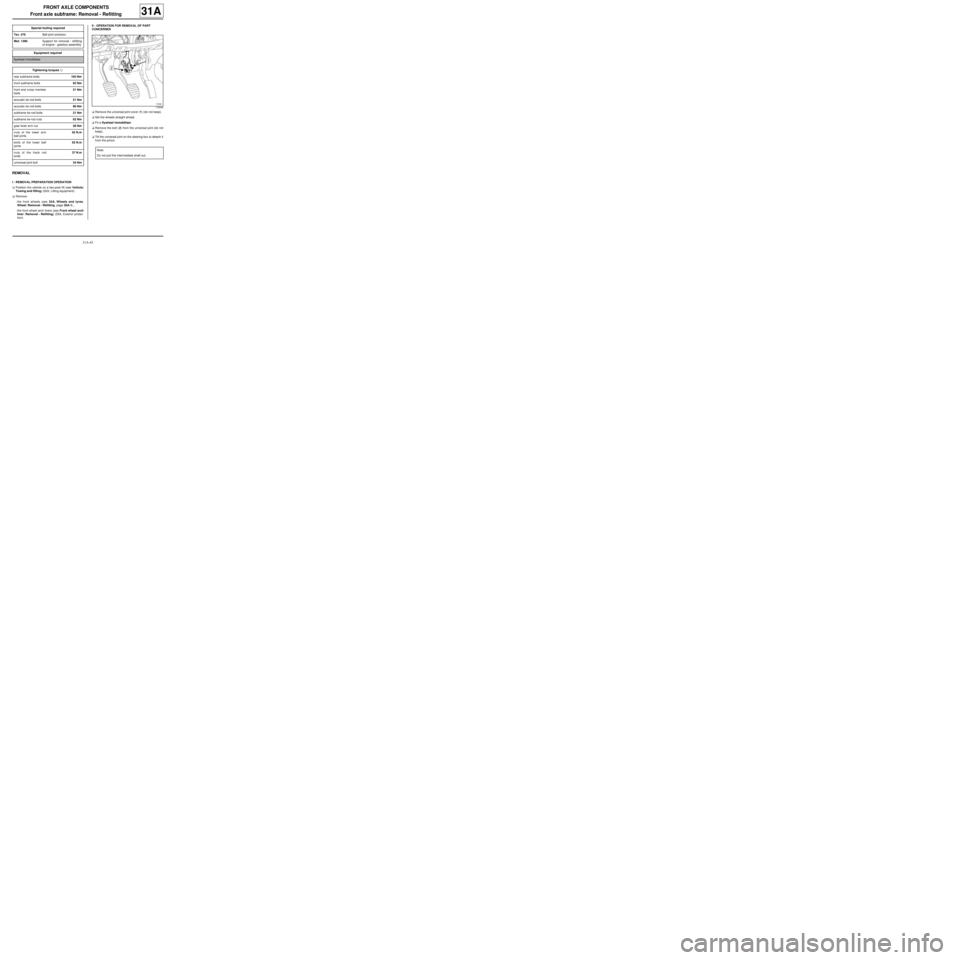
aRemove the universal joint cover (1) (do not keep).
aSet the wheels straight ahead.
aFit a flywheel immobiliser.
aRemove the bolt (2) from the universal joint (do not
keep).
aTilt the universal joint on the steering box to detach it
from the pinion. Special tooling required
Tav. 476Ball joint extractor.
Mot. 1390Suppor t for removal - refitting
of engine - gearbox assembly
Equipment required
flywheel immobiliser
Tightening torquesm
rear subframe bolts105 Nm
front subframe bolts62 Nm
front end cross member
bolts21 Nm
acoustic tie-rod bolts21 Nm
acoustic tie-rod bolts90 Nm
subframe tie-rod bolts21 Nm
subframe tie-rod nuts62 Nm
gear lever arm nut28 Nm
nuts of the lower arm
ball joints62 N.m
bolts of the lower ball
joints62 N.m
nuts of the track rod
ends37 N.m
universal joint bolt24 Nm
119544
Note:
Do not pull the intermediate shaft out.
Page 91 of 281
31A-48
FRONT AXLE COMPONENTS
Front axle subframe: Removal - Refitting
31A
II - REFITTING OPERATION FOR PART
CONCERNED
aRefit the speed selection cable guide on the sub-
frame.
aRefit:
-the front driveshaft lower arms (see 31A, Front
axle components, Front driveshaft lower arm:
Removal - Refitting, page 31A-33) ,
-the front anti-roll bar (see 31A, Front axle compo-
nents, Front anti-roll bar: Removal - Refitting,
page 31A-52) ,
-the steering box (see 36A, Steering assembly,
Steering box: Removal - Refitting, page 36A-1) .
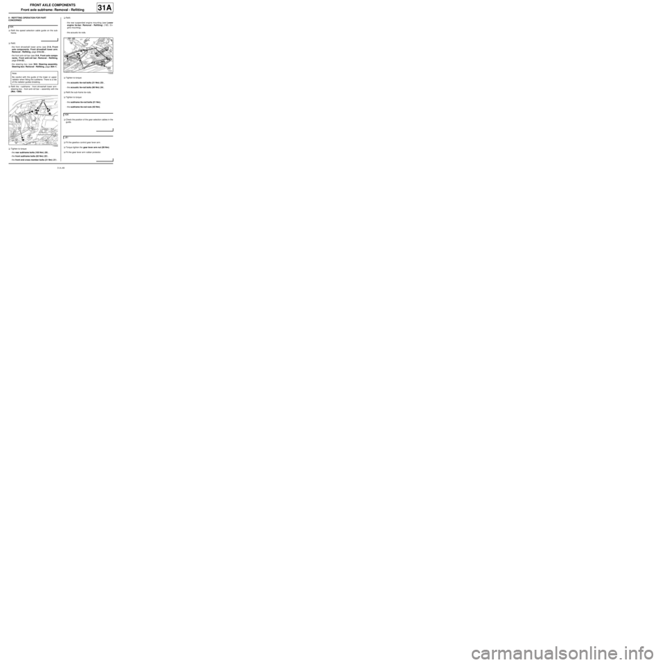
aRefit the « subframe - front driveshaft lower arm -
steering box - front anti-roll bar » assembly with the
(Mot. 1390).
aTighten to torque:
-the rear subframe bolts (105 Nm) (20) ,
-the front subframe bolts (62 Nm) (22) ,
-the front end cross member bolts (21 Nm) (21) .aRefit:
-the rear suspended engine mounting (see Lower
engine tie-bar: Removal - Refitting) (19D, En-
gine mounting),
-the acoustic tie rods.
aTighten to torque:
-the acoustic tie-rod bolts (21 Nm) (23) ,
-the acoustic tie-rod bolts (90 Nm) (24) .
aRefit the sub-frame tie-rods.
aTighten to torque:
-the subframe tie-rod bolts (21 Nm),
-the subframe tie-rod nuts (62 Nm).
aCheck the position of the gear selection cables in the
guide.
aFit the gearbox control gear lever arm.
aTorque tighten the gear lever arm nut (28 Nm).
aFit the gear lever arm rubber protector. K9K
Note:
Be careful with the guide of the lower or upper
radiator when fitting the subframe. There is a risk
of the radiator guides breaking.
119336
119335
K9K
JB1
Page 92 of 281
31A-49
FRONT AXLE COMPONENTS
Front axle subframe: Removal - Refitting
31A
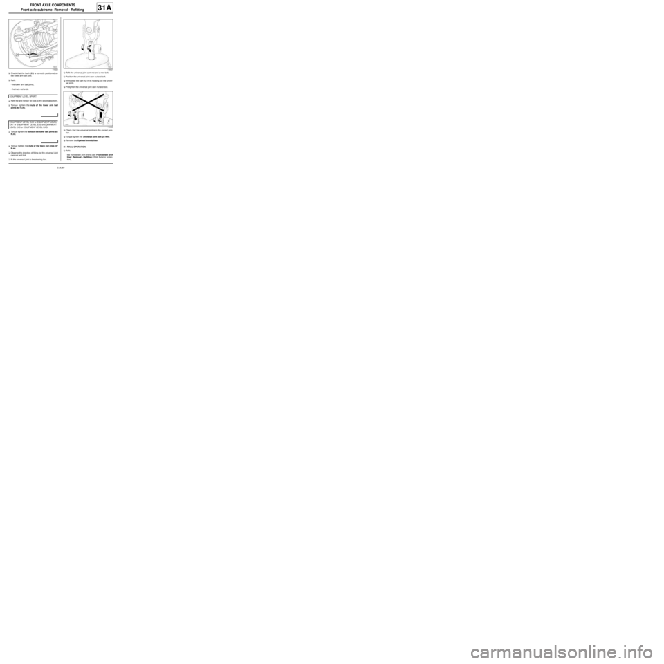
aCheck that the bush (25) is correctly positioned on
the lower arm ball joint.
aRefit:
-the lower arm ball joints,
-the track rod ends.
aRefit the anti-roll bar tie-rods to the shock absorbers.
aTorque tighten the nuts of the lower arm ball
joints (62 N.m).
aTorque tighten the bolts of the lower ball joints (62
N.m).
aTorque tighten the nuts of the track rod ends (37
N.m).
aObserve the direction of fitting for the universal joint
cam nut and bolt.
afit the universal joint to the steering box.aRefit the universal joint cam nut and a new bolt.
aPosition the universal joint cam nut and bolt.
aImmobilise the cam nut in its housing (on the univer-
sal joint).
aPretighten the universal joint cam nut and bolt.
aCheck that the universal joint is in the correct posi-
tion.
aTorque tighten the universal joint bolt (24 Nm).
aRemove the flywheel immobiliser.
III - FINAL OPERATION.
aRefit:
-the front wheel arch liners (see Front wheel arch
liner: Removal - Refitting) (55A, Exterior protec-
tion),
119223
EQ UIPMENT LEVEL SPORT
EQUIPMENT LEVEL EA0 or EQUIPMENT LEVEL
EA1 or EQUIPMENT LEVEL EA3 or EQUIPMENT
LEVEL EA5 or EQUIPMENT LEVEL EAG
116021
116022