torque RENAULT TWINGO 2009 2.G Chasiss Owner's Guide
[x] Cancel search | Manufacturer: RENAULT, Model Year: 2009, Model line: TWINGO, Model: RENAULT TWINGO 2009 2.GPages: 281
Page 57 of 281
31A-14
FRONT AXLE COMPONENTS
Front brake calliper mounting: Removal - Refitting
EQ UIPMENT LEVEL EA0 or EQUIPMENT LEVEL EA1 or EQUIPMENT LEVEL EA3 or EQUIPMENT LEVEL EA5
or EQUIPMENT LEVEL EAG or EQUIPMENT LEVEL EZ2 or EQUIPMENT LEVEL EZ4
31A
REMOVAL
I - REMOVAL PREPARATION OPERATION
aPosition the vehicle on a two-post lift (see Vehicle:
Towing and lifting) (02A, Lifting equipment).
aRemove:
-the front wheel (see 35A, Wheels and tyres,
Wheel: Removal - Refitting, page 35A-1) ,
-the front brake pads (see 31A, Front axle compo-
nents, Front brake pads: Removal - Refitting,
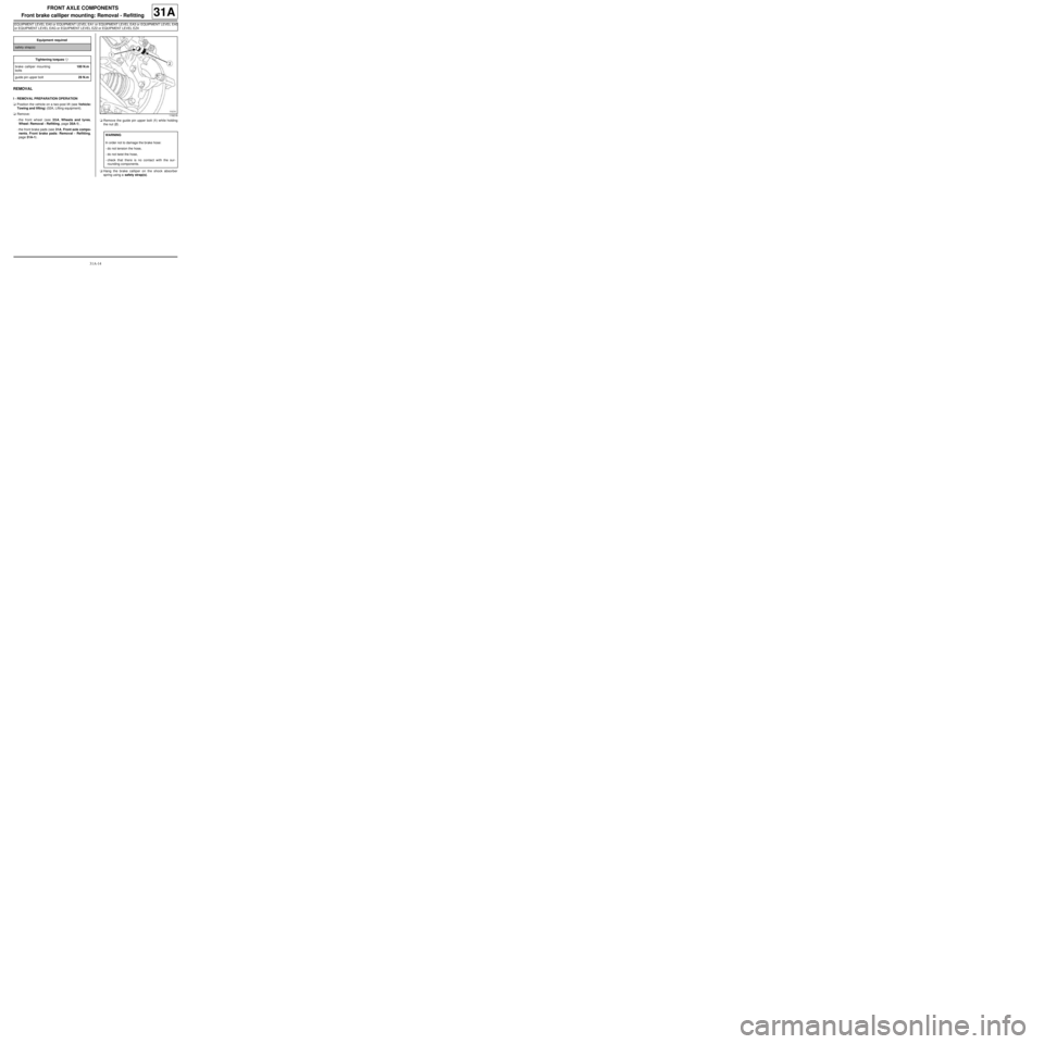
page 31A-1) .aRemove the guide pin upper bolt (1) while holding
the nut (2) .
aHang the brake calliper on the shock absorber
spring using a safety strap(s). Equipment required
safety strap(s)
Tightening torquesm
brake calliper mounting
bolts100 N.m
guide pin upper bolt29 N.m
119218
WARNING
In order not to damage the brake hose:
-do not tension the hose,
-do not twist the hose,
-check that there is no contact with the sur-
rounding components.
Page 58 of 281
31A-15
FRONT AXLE COMPONENTS
Front brake calliper mounting: Removal - Refitting
EQ UIPMENT LEVEL EA0 or EQUIPMENT LEVEL EA1 or EQUIPMENT LEVEL EA3 or EQUIPMENT LEVEL EA5
or EQUIPMENT LEVEL EAG or EQUIPMENT LEVEL EZ2 or EQUIPMENT LEVEL EZ4
31A
II - REMOVAL OPERATION
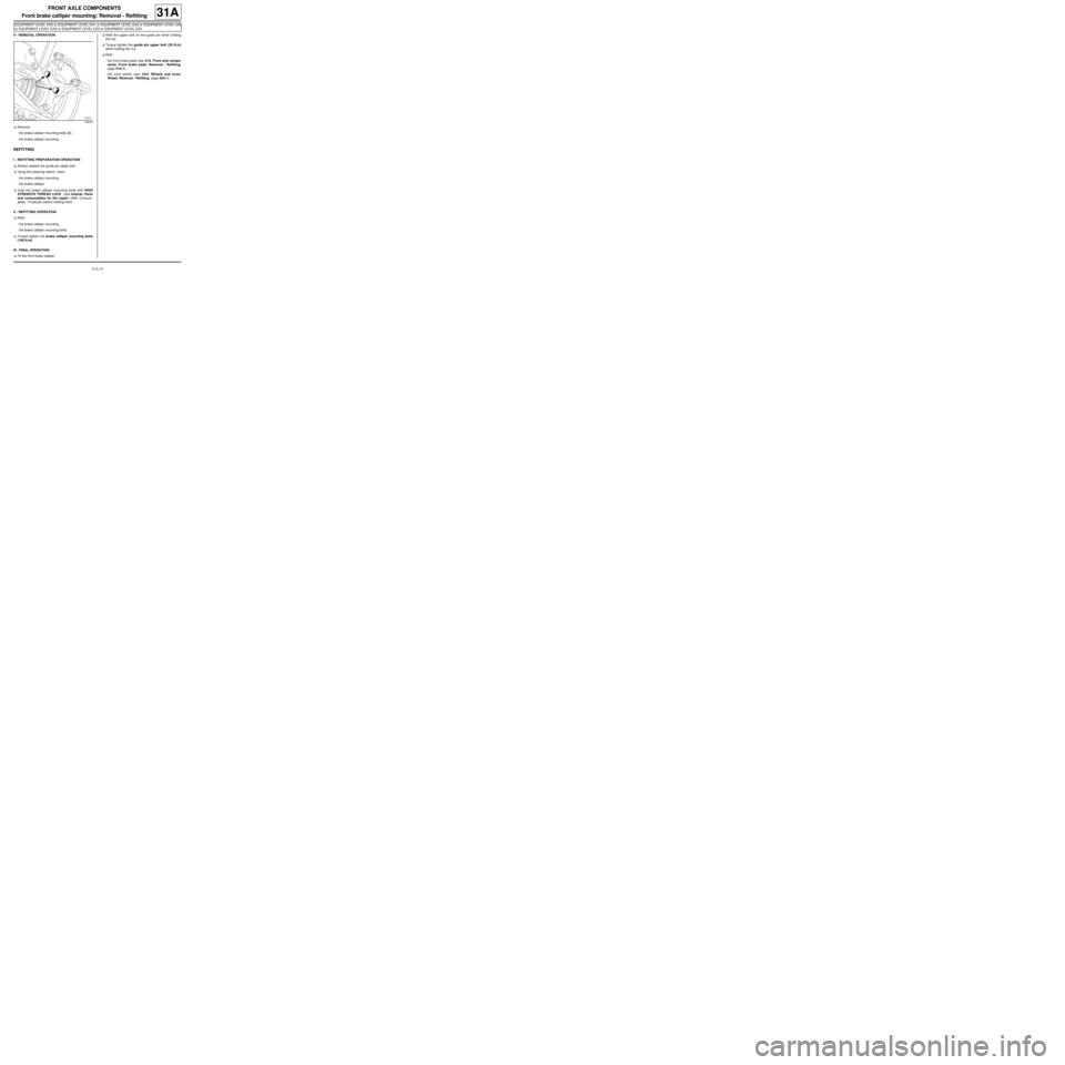
aRemove:
-the brake calliper mounting bolts (3) ,
-the brake calliper mounting.
REFITTING
I - REFITTING PREPARATION OPERATION
aAlways replace the guide pin upper bolt.
aUsing the cleaning station, clean:
-the brake calliper mounting,
-the brake calliper.
aCoat the brake calliper mounting bolts with HIGH
STRENGTH THREAD LOCK (see Vehicle: Parts
and consumables for the repair) (04B, Consum-
ables - Products) before refitting them.
II - REFITTING OPERATION
aRefit:
-the brake calliper mounting,
-the brake calliper mounting bolts.
aTorque tighten the brake calliper mounting bolts
(100 N.m).
III - FINAL OPERATION
aFit the front brake calliper.aRefit the upper bolt on the guide pin while holding
the nut.
aTorque tighten the guide pin upper bolt (29 N.m)
while holding the nut.
aRefit:
-the front brake pads (see 31A, Front axle compo-
nents, Front brake pads: Removal - Refitting,
page 31A-1) ,
-the front wheel (see 35A, Wheels and tyres,
Wheel: Removal - Refitting, page 35A-1) .
119219
Page 59 of 281
31A-16
FRONT AXLE COMPONENTS
Front brake calliper mounting: Removal - Refitting
EQ UIPMENT LEVEL SPORT
31A
REMOVAL
I - REMOVAL PREPARATION OPERATION
aPosition the vehicle on a two-post lift (see Vehicle:
Towing and lifting) (02A, Lifting equipment).
aRemove:
-the front wheel (see 35A, Wheels and tyres,
Wheel: Removal - Refitting, page 35A-1) ,
-the front brake pads (see 31A, Front axle compo-
nents, Front brake pads: Removal - Refitting,
page 31A-1) .II - REMOVAL OPERATION
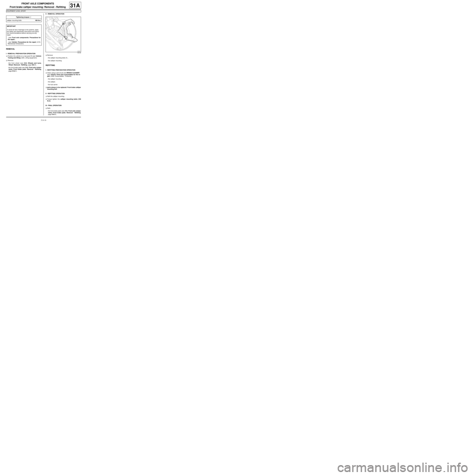
aRemove:
-the calliper mounting bolts (1) ,
-the calliper mounting.
REFITTING
I - REFITTING PREPARATION OPERATION
aClean using a wire brush and BRAKE CLEANER
(see Vehicle: Parts and consumables for the re-
pair) (04B, Consumables - Products):
-the calliper mounting,
-the calliper,
-the hub carrier.
aparts always to be replaced: Front brake calliper
mounting bolt.
II - REFITTING OPERATION
aRefit the calliper mounting.
aTorque tighten the calliper mounting bolts (100
N.m).
III - FINAL OPERATION
aRefit:
-the front brake pads (see 31A, Front axle compo-
nents, Front brake pads: Removal - Refitting,
page 31A-1) , Tightening torquesm
calliper mounting bolts100 N.m
IMPORTANT
To avoid all risk of damage to the systems, apply
the safety and cleanliness instructions and opera-
tion recommendations before carrying out any
repair:
- (see Front axle components: Precautions for
the repair) ,
- (see Vehicle: Precautions for the repair) (01D,
Mechanical introduction).
145125
Page 61 of 281
31A-18
FRONT AXLE COMPONENTS
Front brake disc protector: Removal - Refitting
31A
REMOVAL
I - REMOVAL PREPARATION OPERATION
aPosition the vehicle on a two-post lift (see Vehicle:
Towing and lifting) (MR 411, 02A, Lifting equip-
ment).
aRemove:
-the front wheel (see 35A, Wheels and tyres,
Wheel: Removal - Refitting, page 35A-1) ,
-the front brake pads (see 31A, Front axle compo-
nents, Front brake pads: Removal - Refitting,
page 31A-1) ,
-the calliper mounting (see 31A, Front axle com-
ponents, Front brake calliper mounting: Re-
moval - Refitting, page 31A-14) ,
-the front brake disc (see 31A, Front axle compo-
nents, Front brake disc: Removal - Refitting,
page 31A-19) ,
-the hub carrier (see 31A, Front axle components,
Front driveshaft hub carrier: Removal - Refit-
ting, page 31A-23) ,
-the hub carrier bearing (see 31A, Front axle com-
ponents, Front hub carrier bearing: Removal -
Refitting, page 31A-26) .
II - OPERATION FOR REMOVAL OF PART
CONCERNED
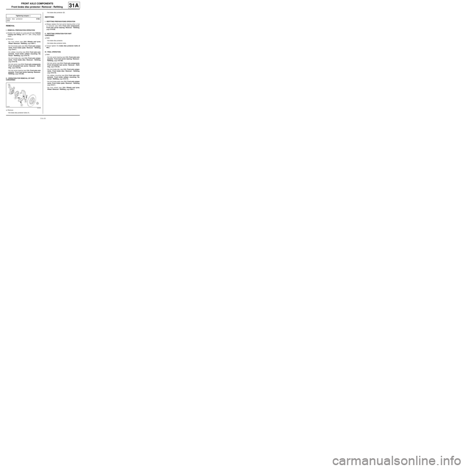
aRemove:
-the brake disc protector bolts (1) ,-the brake disc protector (2) .
REFITTING
I - REFITTING PREPARATIONS OPERATION
aAlways replace the hub carrier bearing when a hub
is removed (see 31A, Front axle components,
Front hub carrier bearing: Removal - Refitting,
page 31A-26) .
II - REFITTING OPERATION FOR PART
CONCERNED
aRefit:
-the brake disc protector,
-the brake disc protector bolts.
aTorque tighten the brake disc protector bolts (8
Nm ).
III - FINAL OPERATION.
aRefit:
-the hub carrier bearing (see 31A, Front axle com-
ponents, Front hub carrier bearing: Removal -
Refitting, page 31A-26) ,
-the hub carrier (see 31A, Front axle components,
Front driveshaft hub carrier: Removal - Refit-
ting, page 31A-23) ,
-the front brake disc (see 31A, Front axle compo-
nents, Front brake disc: Removal - Refitting,
page 31A-19) ,
-the calliper mounting (see 31A, Front axle com-
ponents, Front brake calliper mounting: Re-
moval - Refitting, page 31A-14) ,
-the front brake pads (see 31A, Front axle compo-
nents, Front brake pads: Removal - Refitting,
page 31A-1) ,
-the front wheel (see 35A, Wheels and tyres,
Wheel: Removal - Refitting, page 35A-1) . Tightening torquesm
brake disc protector
bolts8 Nm
121610
Page 63 of 281
31A-20
FRONT AXLE COMPONENTS
Front brake disc: Removal - Refitting
31A
aRemove the brake pads (see 31A, Front axle com-
ponents, Front brake pads: Removal - Refitting,
page 31A-1)
aRemove the "brake calliper mounting - brake calli-
per" assembly (2) (see 31A, Front axle compo-
nents, Front brake calliper mounting: Removal -
Refitting, page 31A-14) .
aHang the "brake calliper mounting - brake calliper"
assembly (2) on the suspension spring.II - OPERATION FOR REMOVAL OF PART
CONCERNED
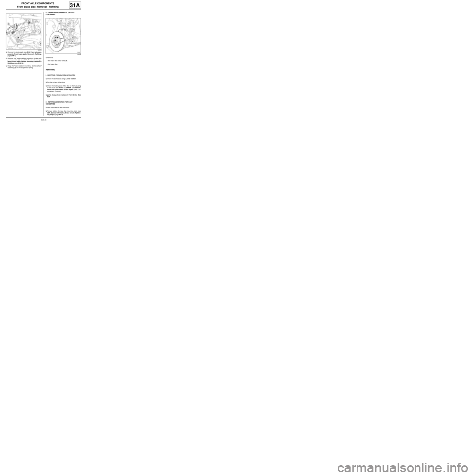
aRemove:
-the brake disc bolt or bolts (3) ,
-the brake disc.
REFITTING
I - REFITTING PREPARATION OPERATION
aClean the brake discs using a parts washer.
aDry the surface of the discs.
aClean the mating faces of the disc on the hub using
a wire brush and BRAKE CLEANER (see Vehicle:
Parts and consumables for the repair) (04B, Con-
sumables - Products).
aparts always to be replaced: Front brake disc
bolt
II - REFITTING OPERATION FOR PART
CONCERNED
aRefit the brake disc with new bolts.
aTorque tighten the new disc mounting bolts (see
30A, General information, Brake circuit: Tighten-
ing torque, page 30A-6)
125059
125056
Page 66 of 281
31A-23
FRONT AXLE COMPONENTS
Front driveshaft hub carrier: Removal - Refitting
31A
REMOVAL
I - REMOVAL PREPARATION OPERATION
aPosition the vehicle on a two-post lift (see Vehicle:
Towing and lifting) (MR 411, 02A, Lifting equip-
ment).
aRemove:
-the front wheel on the side in question (see 35A,
Wheels and tyres, Wheel: Removal - Refitting,
page 35A-1) ,
-the front brake pads of the side in question (see
31A, Front axle components, Front brake pads:
Removal - Refitting, page 31A-1) ,
aRemove:
-the front brake calliper mounting (see 31A, Front
axle components, Front brake calliper mount-
ing: Removal - Refitting, page 31A-14) ,
-the front brake disc (see 31A, Front axle compo-
nents, Front brake disc: Removal - Refitting,
page 31A-19) ,
-the front wheel speed sensor on the hub carrier
(see 38C, Anti-lock braking system, Front wheel
speed sensor: Removal - Refitting, page 38C-
15) .II - OPERATION FOR REMOVAL OF PART
CONCERNED
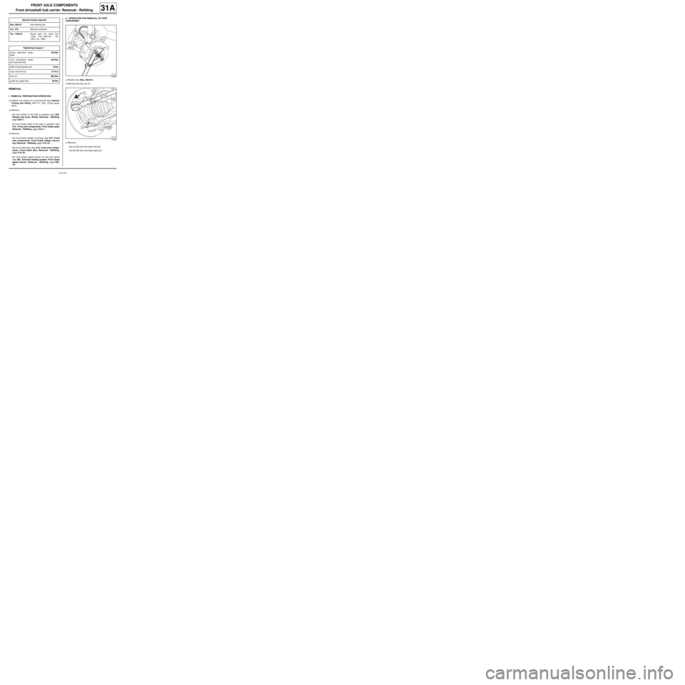
aPosition the (Rou. 604-01).
aRemove the hub nut (1) .
aRemove:
-the nut (2) from the track rod end,
-the bolt (3) from the lower ball joint. Special tooling required
Rou. 604-01Hub locking tool.
Tav. 476Ball joint extractor.
Tav. 1420-01Screw jack for tools Tav.
1420, Tav.1050-04 , Tar.
1454, Tar. 1850.
Tightening torquesm
shock absorber lower
bolts105 Nm
front driveshaft lower
arm ball joint bolt105 Nm
ABS wiring bracket bolt8 Nm
track rod end nut37 N.m
hub nut280 Nm
guide pin upper bolt29 Nm
119543
119222
Page 67 of 281
31A-24
FRONT AXLE COMPONENTS
Front driveshaft hub carrier: Removal - Refitting
31A
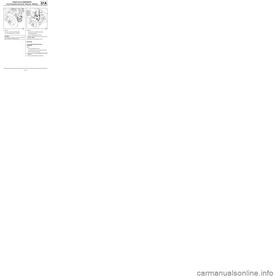
aRemove:
-the track rod end using the (Tav. 476),
-the front driveshaft lower arm ball joint.aRemove:
-the bolt (4) from the ABS wiring bracket,
-the ABS wiring bracket,
-the shock absorber lower studs (5) .
aSeparate the driveshaft from the hub carrier using
the (Tav. 1420-01).
aRemove the front driveshaft hub carrier.
REFITTING
I - REFITTING OPERATION FOR PART
CONCERNED
aRefit:
-the front driveshaft hub carrier,
-the driveshaft into the front driveshaft hub-carrier,
-the shock absorber lower bolts.
aTorque tighten the shock absorber lower bolts
(105 Nm).
aFit the front driveshaft lower arm ball joint.
119345
WARNING
To prevent any damage, do not use the lower
arm as support for the lifting system.
119221
Page 68 of 281
31A-25
FRONT AXLE COMPONENTS
Front driveshaft hub carrier: Removal - Refitting
31A
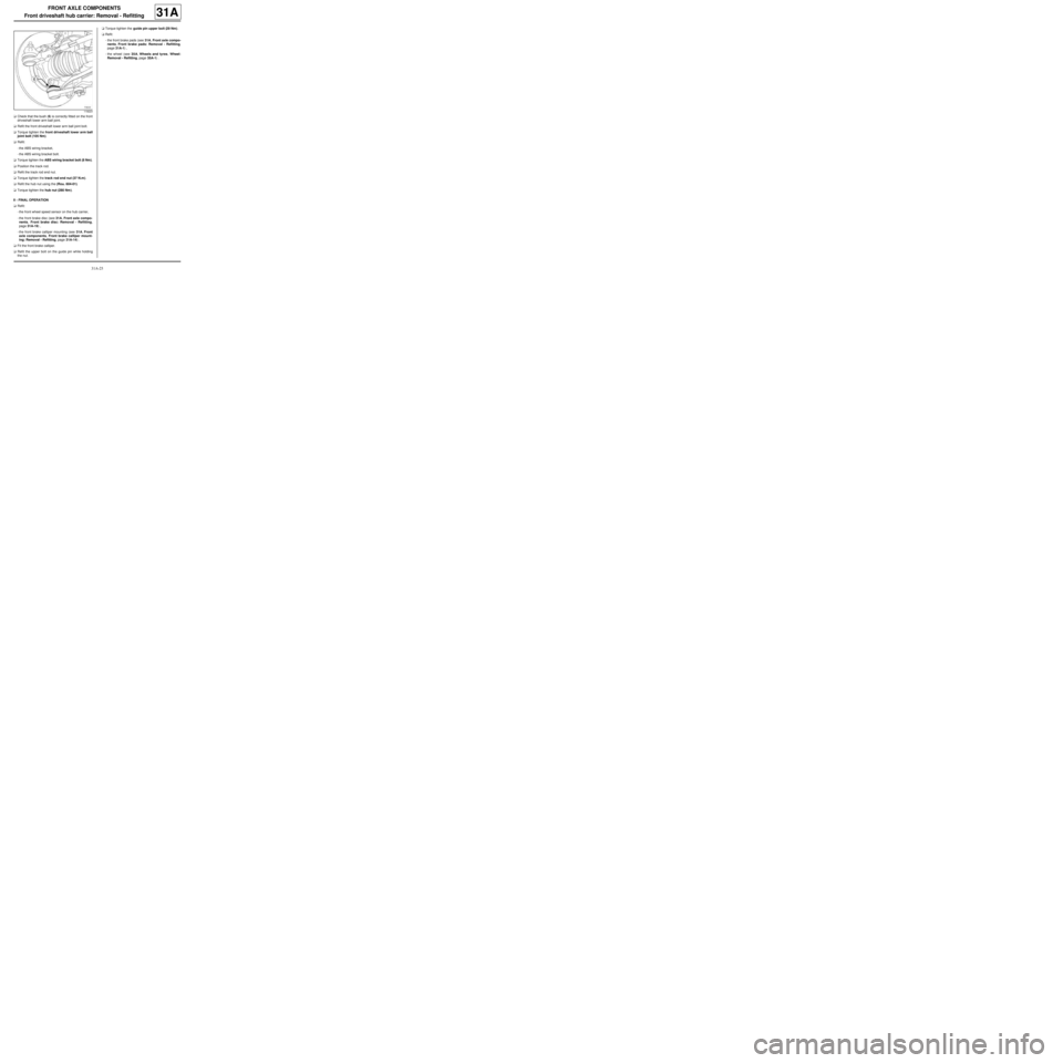
aCheck that the bush (6) is correctly fitted on the front
driveshaft lower arm ball joint.
aRefit the front driveshaft lower arm ball joint bolt.
aTorque tighten the front driveshaft lower arm ball
joint bolt (105 Nm).
aRefit:
-the ABS wiring bracket,
-the ABS wiring bracket bolt.
aTorque tighten the ABS wiring bracket bolt (8 Nm).
aPosition the track rod.
aRefit the track rod end nut.
aTorque tighten the track rod end nut (37 N.m).
aRefit the hub nut using the (Rou. 604-01).
aTorque tighten the hub nut (280 Nm).
II - FINAL OPERATION
aRefit:
-the front wheel speed sensor on the hub carrier,
-the front brake disc (see 31A, Front axle compo-
nents, Front brake disc: Removal - Refitting,
page 31A-19) ,
-the front brake calliper mounting (see 31A, Front
axle components, Front brake calliper mount-
ing: Removal - Refitting, page 31A-14) .
aFit the front brake calliper.
aRefit the upper bolt on the guide pin while holding
the nut.aTorque tighten the guide pin upper bolt (29 Nm).
aRefit:
-the front brake pads (see 31A, Front axle compo-
nents, Front brake pads: Removal - Refitting,
page 31A-1) ,
-the wheel (see 35A, Wheels and tyres, Wheel:
Removal - Refitting, page 35A-1) .
119223
Page 72 of 281
31A-29
FRONT AXLE COMPONENTS
Front shock absorber and spring: Removal - Refitting31A
REMOVAL
I - REMOVAL PREPARATION OPERATION
aPosition the vehicle on a two-post lift (see Vehicle:
Towing and lifting) (02A, Lifting equipment).
aDisconnect the battery (see ) (80A, Battery).
aRemove the front wheels (see 35A, Wheels and ty-
res, Wheel: Removal - Refitting, page 35A-1) .II - OPERATION FOR REMOVAL OF PART
CONCERNED
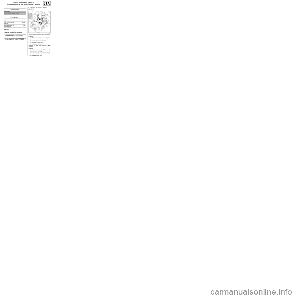
aDetach the wiring (1) from the wheel speed sensor.
aRemove:
-the bolt (2) of the wheel speed sensor wiring brack-
et,
-the wheel speed sensor wiring bracket,
-the shock absorber base nuts (3) ,
-the shock absorber base bolts.
aHang the hub carrier on the body using a safety
strap(s).
aRemove:
-the windscreen wiper arms (see Windscreen wip-
er arm: Removal - Refitting) ,
-the scuttle panel grille (see Scuttle panel grille:
Removal - Refitting) (56A, Exterior equipment),
-the shock absorber nut cover. Equipment required
safety strap(s)
spanner for shock absorber rod nut
Tightening torquesm
new shock absorber rod
nut62 N.m
new shock absorber
base nuts105 N.m
wheel speed sensor wir-
ing bracket bolt8 N.m
119221
Page 74 of 281
31A-31
FRONT AXLE COMPONENTS
Front shock absorber and spring: Removal - Refitting31A
a
II - REFITTING OPERATION FOR PART
CONCERNED
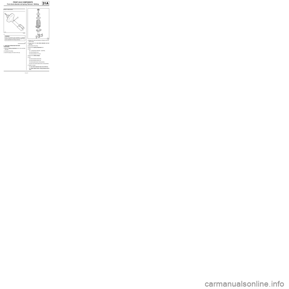
aPlace the spring compressor tool in the vice fitted
with jaws.
aCompress the spring.
aInsert the spring in the neck of the cup.aRespect the order and direction of fitting for the con-
stituent parts.
aTorque tighten the new shock absorber rod nut
(62 N.m).
aDecompress the spring.
aRemove the spring compressor tool.
aRefit:
-the « spring/shock absorber » assembly,
-the shock absorber cup,
-the shock absorber nut cover.
aRemove the safety strap(s).
aRefit:
-the shock absorber base bolts,
-the shock absorber base nuts,
-the wheel speed sensor wiring bracket,
-the bolt of the wheel speed sensor wiring bracket.
aTighten to torque:
-the new shock absorber base nuts (105 N.m),
-the wheel speed sensor wiring bracket bolt (8
N.m). RIGHT-HAND DRIVE
139405
WARNING
Only the left-hand shock absorber is supplied
with its marking to prevent the left and right-hand
shock absorbers from being mixed up.
119654