engine RENAULT TWINGO 2009 2.G Electrical Equipment - Petrol Injection Manual PDF
[x] Cancel search | Manufacturer: RENAULT, Model Year: 2009, Model line: TWINGO, Model: RENAULT TWINGO 2009 2.GPages: 348
Page 99 of 348
17B-99V7 MR-413-X44-17B000$132.mif
PETROL INJECTION
Fault finding – Interpretation of faults17B
SIM 32 Injection
Program no.: D3
Vdiag No.: 44, 4C, 50
and 54
DF085
PRESENT
OR
STOREDFUEL PUMP RELAY CONTROL CIRCUITCO: Open circuit
CC.0: Short circuit to earth
CC.1: Short circuit to + 12 V
1.DEF: EOBD
NOTESConditions for applying the fault finding procedure to stored faults:
The fault is declared present with the ignition on or the engine running, or during
command AC015 Fuel pump relay.
Special notes:
CO/CC.1: The effect of the fault is the same as running out of fuel. The vehicle stalls
and cannot be restarted.
CC.0: There is danger of fire in the event of petrol leaking during an accident.
Intermittent CO: Risk of intermittent ignition cut-off and draining the battery.
Use the Wiring Diagrams Technical Note for NEW TWINGO, E33, CLIO III,
or MODUS.
Check the condition of the engine management computer connector (component code 120).
If the connector is faulty and there is a repair method (see Technical Note 6015A, Repairing electrical wiring,
Wiring: Precautions for repair), repair the connector, otherwise replace the wiring.
For NEW TWINGO or E33:
Check the condition of the fuel pump relay (component code 236).
If the connectors are faulty and if there is a repair procedure (see Technical Note 6015A, Repairing electrical
wiring, Wiring: Precautions for repair), repair the connector, otherwise replace the wiring.
Use the "universal bornier" to check the insulation and continuity of the following connection:
●3AC between components 236 and 120,
If the connection or connections are faulty and there is a repair procedure (see Technical Note 6015A, Electrical
wiring repair, Wiring: Precautions for repair), repair the wiring, otherwise replace it.
Check for an earth during activation of command AC015 Fuel pump relay.
SIM32_V44_DF085/SIM32_V4C_DF085/SIM32_V50_DF085/SIM32_V54_DF085
AFTER REPAIRFollow the instructions to confirm repair:
- If the fault is present, continue to deal with the fault.
- If the fault is stored, ignore it.
Deal with any other faults.
Clear the stored faults.
Page 100 of 348
17B-100V7 MR-413-X44-17B000$132.mif
PETROL INJECTION
Fault finding – Interpretation of faults17B
SIM 32 Injection
Program no.: D3
Vdiag No.: 44, 4C, 50
and 54
DF085
CONTINUED
With the ignition on, if the + 12 V is still not present on the fuel pump relay connector, there is a fault in the engine
fuse and relay box.
Run fault finding on the engine fuse and relay box to check the continuity of the following connection:
●BP17 between components 120 and 597,
●BP17 between components 1033 and 597.
If the connection is faulty and if there is a repair procedure (see Technical Note 6015A, Electrical wiring repair,
Wiring: Precautions for repair), repair the wiring, otherwise replace it.
If the fault is still present, check the battery and run fault finding on the charging circuit (see Technical Note 6014A,
Checking the charging circuit).
For CLIO III or MODUS:
Check the condition of the Protection and Switching Unit (see Wiring Diagram Technical Note, CLIO III or
MODUS, component code 1337).
If the connectors are faulty and if there is a repair procedure (see Technical Note 6015A, Repairing electrical
wiring, Wiring: Precautions for repair), repair the connector, otherwise replace the wiring.
Use the "universal bornier" to check the insulation and continuity of the following connection:
●3AC between components 1337 and 120.
If the connection or connections are faulty and there is a repair procedure (see Technical Note 6015A, Electrical
wiring repair, Wiring: Precautions for repair), repair the wiring, otherwise replace it.
Check for an earth during activation of command AC015 Fuel pump relay.
If the fault is still present, there is a fault in the Protection and Switching Unit (the fuel pump relay is in the Protection
and Switching Unit and cannot be dismantled).
Run fault finding on the UPC, component code 1337 (see 87G, Engine compartment connection unit).
If the fault is still present, contact the Techline.
AFTER REPAIRFollow the instructions to confirm repair:
- If the fault is present, continue to deal with the fault.
- If the fault is stored, ignore it.
Deal with any other faults.
Clear the stored faults.
Page 101 of 348
17B-101V7 MR-413-X44-17B000$132.mif
PETROL INJECTION
Fault finding – Interpretation of faults17B
SIM 32 Injection
Program no.: D3
Vdiag No.: 44, 4C, 50
and 54
DF089
PRESENT
OR
STOREDINLET MANIFOLD PRESSURE SENSOR CIRCUIT
1.DEF: Signal incoherent
2.DEF: Abnormal voltage
3.DEF: EOBD
NOTESConditions for applying the fault finding procedure to stored faults:
1.DEF: The fault is declared present with the engine running after a few seconds.
2.DEF: The fault is declared present with the engine running.
Special notes:
Minimum idle speed of 900 rpm.
The injection goes into defect mode 5: the ESP and the cruise control - speed limiter
are deactivated. The vehicle stalls under idle speed. The level 1 and OBD fault
warning lights are lit.
Use the Wiring Diagrams Technical Note for NEW TWINGO, E33, CLIO III,
or MODUS.
Check the condition of the manifold pressure sensor and its connections (component code 147).
If the connector is faulty and there is a repair method (see Technical Note 6015A, Repairing electrical wiring,
Wiring: Precautions for repair), repair the connector, otherwise replace the wiring.
Measure the voltage of the manifold pressure sensor between connections 3FG and 3F.
If the voltage of the manifold pressure sensor is not between:
●4.75 V < X < 5.25 V with the engine stopped, replace the sensor.
Check the condition of the engine management computer connector (component code 120).
If the connector is faulty and there is a repair method (see Technical Note 6015A, Repairing electrical wiring,
Wiring: Precautions for repair), repair the connector, otherwise replace the wiring.
Use the universal bornier to check the insulation and continuity of the following connections:
●3LG between components 147 and 120,
●3F between components 147 and 120,
●3CK between components 147 and 120.
If the connection or connections are faulty and there is a repair procedure (see Technical Note 6015A, Electrical
wiring repair, Wiring: Precautions for repair), repair the wiring, otherwise replace it.
SIM32_V44_DF089/SIM32_V4C_DF089/SIM32_V50_DF089/SIM32_V54_DF089
AFTER REPAIRFollow the instructions to confirm repair:
- If the fault is present, continue to deal with the fault.
- If the fault is stored, ignore it.
Deal with any other faults.
Clear the stored faults.
Page 103 of 348
17B-103V7 MR-413-X44-17B000$132.mif
PETROL INJECTION
Fault finding – Interpretation of faults17B
SIM 32 Injection
Program no.: D3
Vdiag No.: 44, 4C, 50
and 54
DF091
PRESENT
OR
STOREDVEHICLE SPEED SIGNAL
1.DEF: Missing or invalid multiplex signals (fault with computer issuing the signal or
with multiplex line connection)
2.DEF: EOBD
NOTESConditions for applying the fault finding procedure to stored faults:
The fault is declared present when the ignition is switched on or with the engine running.
Run a multiplex network test (see 88B, Multiplex).
If the fault is still present, carry out fault finding on the ABS computer (see 38C, Anti-lock braking system).
Check the condition of the engine management computer connector (component code 120).
If the connector is faulty and there is a repair method (see Technical Note 6015A, Repairing electrical wiring,
Wiring: Precautions for repair), repair the connector, otherwise replace the wiring.
If the fault is still present, contact the Techline.
SIM32_V44_DF091/SIM32_V4C_DF091/SIM32_V50_DF091/SIM32_V54_DF091
AFTER REPAIRFollow the instructions to confirm repair:
- If the fault is present, continue to deal with the fault.
- If the fault is stored, ignore it.
Deal with any other faults.
Clear the stored faults.
Page 104 of 348
17B-104V7 MR-413-X44-17B000$132.mif
PETROL INJECTION
Fault finding – Interpretation of faults17B
SIM 32 Injection
Program no.: D3
Vdiag No.: 44, 4C, 50
and 54
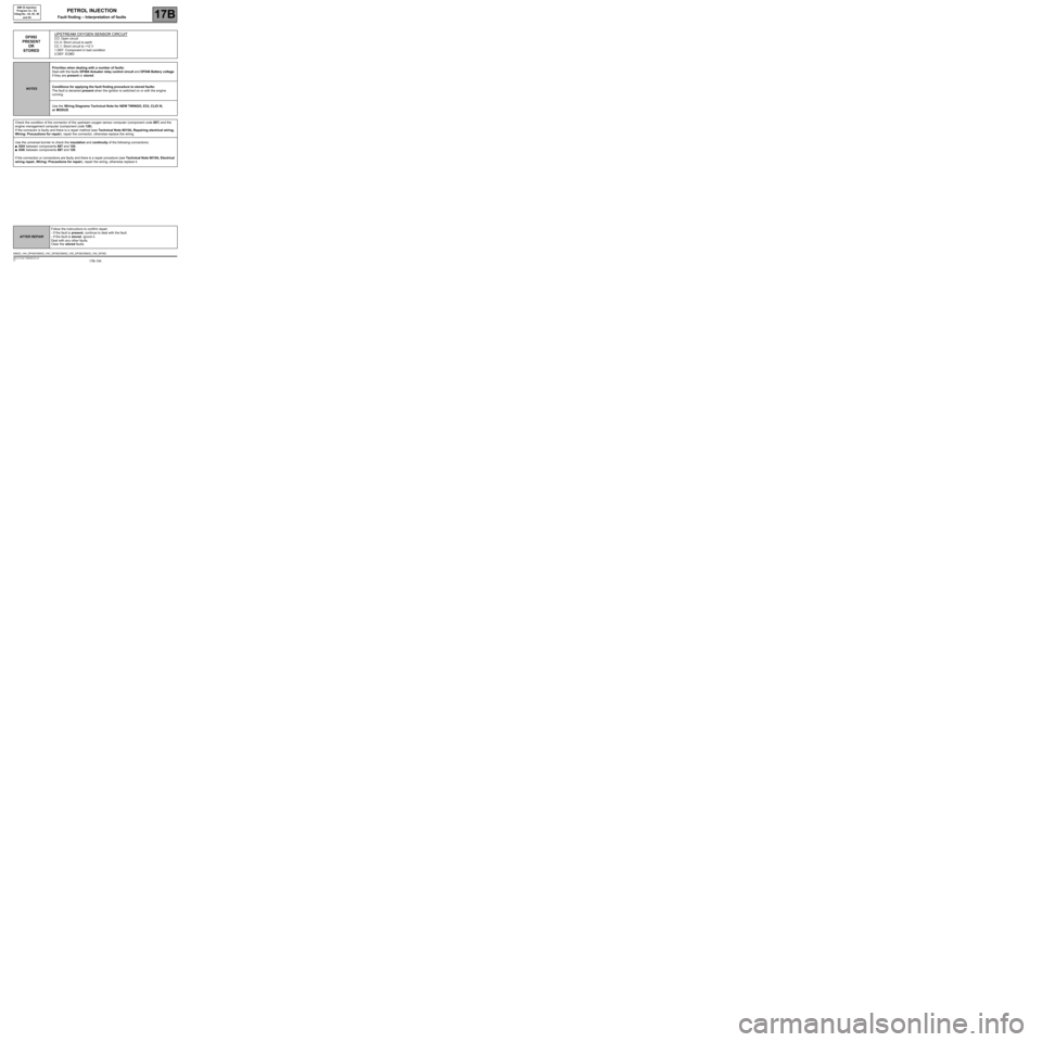
DF092
PRESENT
OR
STOREDUPSTREAM OXYGEN SENSOR CIRCUITCO: Open circuit
CC.0: Short circuit to earth
CC.1: Short circuit to +12 V
1.DEF: Component in bad condition
2.DEF: EOBD
NOTESPriorities when dealing with a number of faults:
Deal with the faults DF084 Actuator relay control circuit and DF046 Battery voltage
if they are present or stored.
Conditions for applying the fault finding procedure to stored faults:
The fault is declared present when the ignition is switched on or with the engine
running.
Use the Wiring Diagrams Technical Note for NEW TWINGO, E33, CLIO III,
or MODUS.
Check the condition of the connector of the upstream oxygen sensor computer (component code 887) and the
engine management computer (component code 120).
If the connector is faulty and there is a repair method (see Technical Note 6015A, Repairing electrical wiring,
Wiring: Precautions for repair), repair the connector, otherwise replace the wiring.
Use the universal bornier to check the insulation and continuity of the following connections:
●3GH between components 887 and 120,
●3GK between components 887 and 120.
If the connection or connections are faulty and there is a repair procedure (see Technical Note 6015A, Electrical
wiring repair, Wiring: Precautions for repair), repair the wiring, otherwise replace it.
SIM32_V44_DF092/SIM32_V4C_DF092/SIM32_V50_DF092/SIM32_V54_DF092
AFTER REPAIRFollow the instructions to confirm repair:
- If the fault is present, continue to deal with the fault.
- If the fault is stored, ignore it.
Deal with any other faults.
Clear the stored faults.
Page 105 of 348
17B-105V7 MR-413-X44-17B000$132.mif
PETROL INJECTION
Fault finding – Interpretation of faults17B
SIM 32 Injection
Program no.: D3
Vdiag No.: 44, 4C, 50
and 54
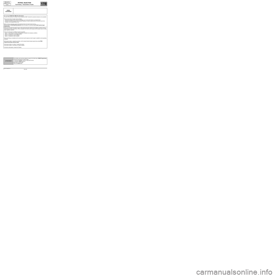
DF092
CONTINUED
Run command SC007 Run OBD Test: O2 sensors.
The aim of this scenario is to detect a fault causing the EOBD* threshold for pollutant emissions to be exceeded.
There are two kinds of oxygen sensor damage:
–mechanical damage to the component (breakage, cut in wire) which leads to an electrical fault,
–chemical or thermal damage to the component leading to a slower response time of the sensor and to the
increase in the average reaction time.
Before carrying out this test, repair all the electrical faults and clear the fault memory.
Deal first with the DF436 Misfiring detection fault and program the flywheel target ET089 Flywheel target
programming.
Perform this test when the engine is warm, which reduces the time it takes for the catalytic converter to heat up.
Fault finding is entirely autonomous. When completed, the throttle control ceases and the engine returns to idling
speed regulation operation.
At the end of this test, four different results are possible:
–status 1: Fault finding not carried out/impossible to establish the necessary conditions.
–status 2: Component in an average condition.
–status 3: Component in good condition.
–status 4: Component in poor condition.
When fault finding is completed and the result read, stop the engine and start it again to establish normal operating
conditions.
If the result is status 1: check for any faults, and the engine flywheel target programming using ET089
Programming engine flywheel target.
If the result is status 2 or status 4, replace the sensor.
If the result is status 3, the sensor is in good condition.
If the fault is still present, contact the Techline.
AFTER REPAIRIf the throttle valve has been replaced, program the throttle stops, RZ005 Programming.
Follow the instructions to confirm repair:
- If the fault is present, continue to deal with the fault.
- If the fault is stored, ignore it.
Deal with any other faults.
Clear the stored faults.
Page 106 of 348
17B-106V7 MR-413-X44-17B000$132.mif
PETROL INJECTION
Fault finding – Interpretation of faults17B
SIM 32 Injection
Program no.: D3
Vdiag No.: 44, 4C, 50
and 54
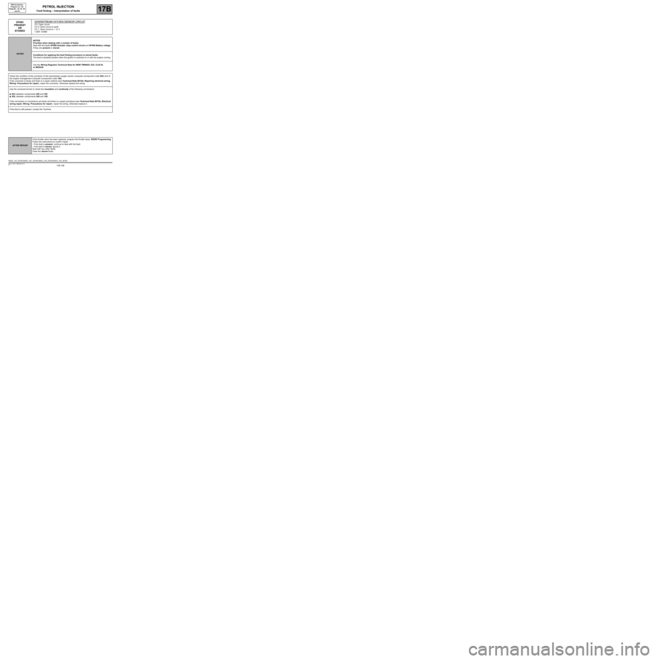
DF093
PRESENT
OR
STOREDDOWNSTREAM OXYGEN SENSOR CIRCUITCO: Open circuit
CC.0: Short circuit to earth
CC.1: Short circuit to + 12 V
1.DEF: EOBD
NOTESNOTES
Priorities when dealing with a number of faults:
Deal with the faults DF084 Actuator relay control circuit and DF046 Battery voltage
if they are present or stored.
Conditions for applying the fault finding procedure to stored faults:
The fault is declared present when the ignition is switched on or with the engine running.
Use the Wiring Diagrams Technical Note for NEW TWINGO, E33, CLIO III,
or MODUS.
Check the condition of the connector of the downstream oxygen sensor computer (component code 242) and of
the engine management computer (component code 120).
If the connector is faulty and there is a repair method (see Technical Note 6015A, Repairing electrical wiring,
Wiring: Precautions for repair), repair the connector, otherwise replace the wiring.
Use the universal bornier to check the insulation and continuity of the following connections:
●3GJ between components 242 and 120,
●3GL between components 242 and 120.
If the connection or connections are faulty and there is a repair procedure (see Technical Note 6015A, Electrical
wiring repair, Wiring: Precautions for repair), repair the wiring, otherwise replace it.
If the fault is still present, contact the Techline.
SIM32_V44_DF093/SIM32_V4C_DF093/SIM32_V50_DF093/SIM32_V54_DF093
AFTER REPAIRIf the throttle valve has been replaced, program the throttle stops, RZ005 Programming.
Follow the instructions to confirm repair:
- If the fault is present, continue to deal with the fault.
- If the fault is stored, ignore it.
Deal with any other faults.
Clear the stored faults.
Page 107 of 348
17B-107V7 MR-413-X44-17B000$132.mif
PETROL INJECTION
Fault finding – Interpretation of faults17B
SIM 32 Injection
Program no.: D3
Vdiag No.: 44, 4C, 50
and 54
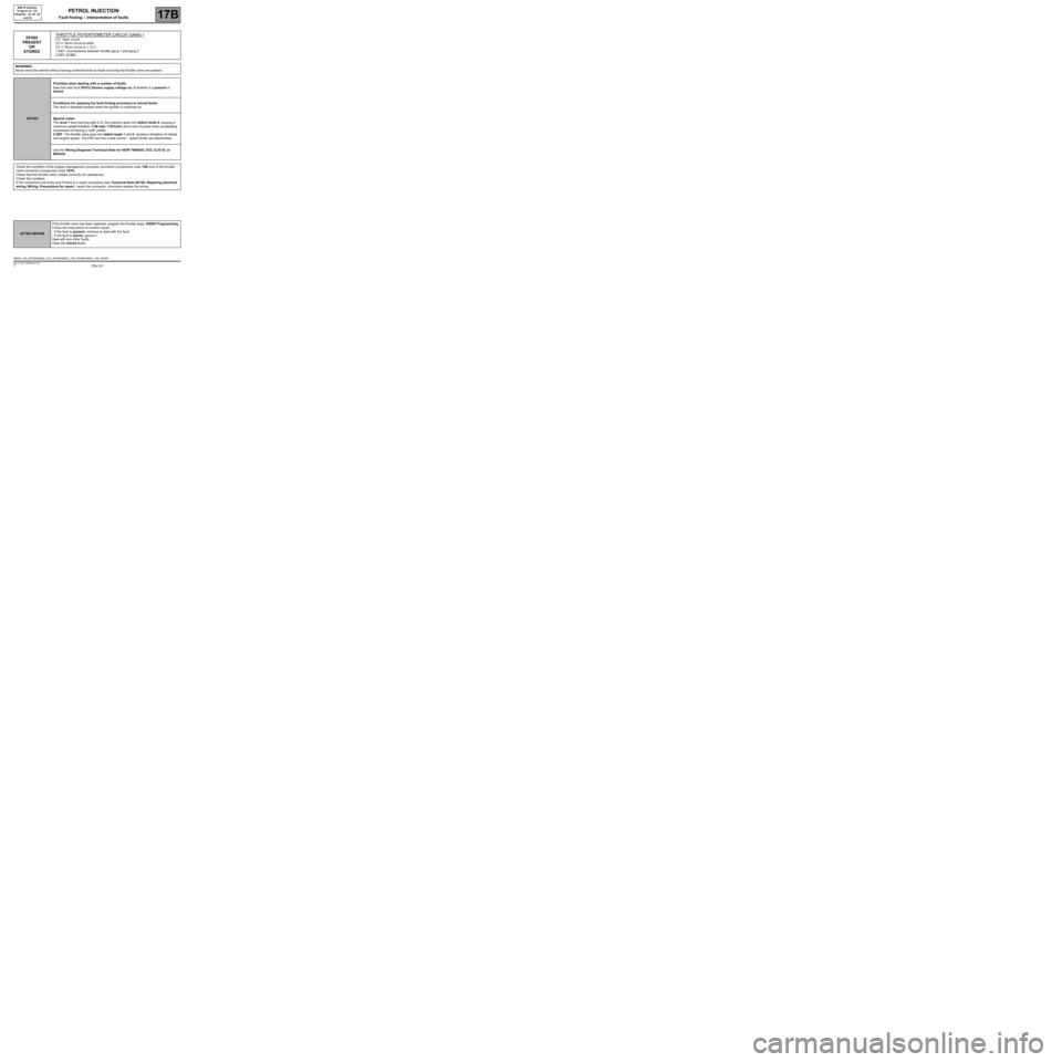
DF095
PRESENT
OR
STOREDTHROTTLE POTENTIOMETER CIRCUIT GANG 1CO: Open circuit
CC.0: Short circuit to earth
CC.1: Short circuit to + 12 V
1.DEF: Inconsistency between throttle gang 1 and gang 2
2.DEF: EOBD
WARNING:
Never drive the vehicle without having confirmed that no faults involving the throttle valve are present.
NOTESPriorities when dealing with a number of faults:
Deal first with fault DF012 Sensor supply voltage no. 2 whether it is present or
stored.
Conditions for applying the fault finding procedure to stored faults:
The fault is declared present when the ignition is switched on.
Special notes:
The level 1 fault warning light is lit, the injection goes into defect mode 4, causing a
maximum speed limitation of 66 mph (110 km/h) and a loss of power when accelerating
(impression of having a "soft" pedal).
2.DEF: The throttle valve goes into defect mode 1 and 2, causing a limitation of vehicle
and engine speed. The ESP and the cruise control - speed limiter are deactivated.
Use the Wiring Diagrams Technical Note for NEW TWINGO, E33, CLIO III, or
MODUS.
Check the condition of the engine management computer connector (component code 120) and of the throttle
valve connector (component code 1076).
Check that the throttle valve rotates correctly (no resistance).
Check the condition.
If the connectors are faulty and if there is a repair procedure (see Technical Note 6015A, Repairing electrical
wiring, Wiring: Precautions for repair), repair the connector, otherwise replace the wiring.
SIM32_V44_DF095/SIM32_V4C_DF095/SIM32_V50_DF095/SIM32_V54_DF095
AFTER REPAIRIf the throttle valve has been replaced, program the throttle stops, RZ005 Programming.
Follow the instructions to confirm repair:
- If the fault is present, continue to deal with the fault.
- If the fault is stored, ignore it.
Deal with any other faults.
Clear the stored faults.
Page 109 of 348
17B-109V7 MR-413-X44-17B000$132.mif
PETROL INJECTION
Fault finding – Interpretation of faults17B
SIM 32 Injection
Program no.: D3
Vdiag No.: 44, 4C, 50
and 54
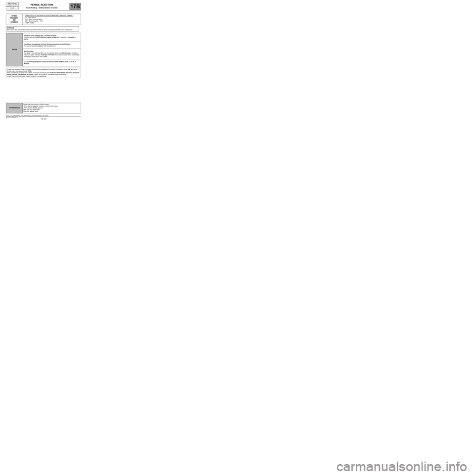
DF096
PRESENT
OR
STOREDTHROTTLE POSITION POTENTIOMETER CIRCUIT GANG 2CO: Open circuit
CC.0: Short circuit to earth
CC.1: Short circuit to + 12 V
1.DEF: EOBD
WARNING:
Never drive the vehicle without having confirmed that no faults involving the throttle valve are present.
NOTESPriorities when dealing with a number of faults:
Deal first with fault DF012 Sensor supply voltage no. 2 whether it is present or
stored.
Conditions for applying the fault finding procedure to stored faults:
The fault is declared present, with the ignition on.
Special notes:
The level 1 fault warning light is lit, the injection goes into defect mode 4, causing a
maximum speed limitation of 66 mph (110 km/h) and a loss of power when accelerating
(impression of having a "soft" pedal).
Use the Wiring Diagrams Technical Note for NEW TWINGO, E33, CLIO III, or
MODUS.
Check the condition of the connector of the engine management computer (component code 120) and of the
throttle valve (component code 1076).
If the connectors are faulty and if there is a repair procedure (see Technical Note 6015A, Repairing electrical
wiring, Wiring: Precautions for repair), repair the connector, otherwise replace the wiring.
Check that the throttle valve rotates correctly (no resistance).
SIM32_V44_DF096/SIM32_V4C_DF096/SIM32_V50_DF096/SIM32_V54_DF096
AFTER REPAIRFollow the instructions to confirm repair:
- If the fault is present, continue to deal with the fault.
- If the fault is stored, ignore it.
Deal with any other faults.
Clear the stored faults.
Page 111 of 348
17B-111V7 MR-413-X44-17B000$132.mif
PETROL INJECTION
Fault finding – Interpretation of faults17B
SIM 32 Injection
Program no.: D3
Vdiag No.: 44, 4C, 50
and 54
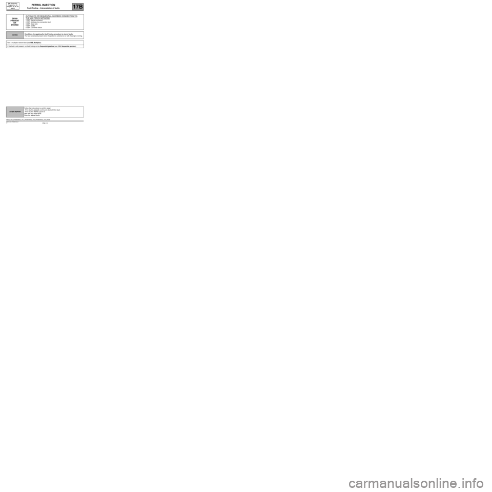
DF099
PRESENT
OR
STOREDAUTOMATIC OR SEQUENTIAL GEARBOX CONNECTION VIA
THE
MULTIPLEX NETWORK
1.DEF: Signal incoherent
2.DEF: Multiplex line connection fault
3.DEF: Gear ratio
4.DEF: EOBD
5.DEF: Converter status
NOTESConditions for applying the fault finding procedure to stored faults:
The fault is declared present when the ignition is switched on or with the engine running.
Run a multiplex network test (see 88B, Multiplex).
If the fault is still present, run fault finding on the Sequential gearbox (see 21B, Sequential gearbox).
SIM32_V44_DF099/SIM32_V4C_DF099/SIM32_V50_DF099/SIM32_V54_DF099
AFTER REPAIRFollow the instructions to confirm repair:
- If the fault is present, continue to deal with the fault.
- If the fault is stored, ignore it.
Deal with any other faults.
Clear the stored faults.