gearbox RENAULT TWINGO 2009 2.G Engine And Peripherals Passenger Compartment Connection Unit OBD Workshop Manual
[x] Cancel search | Manufacturer: RENAULT, Model Year: 2009, Model line: TWINGO, Model: RENAULT TWINGO 2009 2.GPages: 179, PDF Size: 0.57 MB
Page 7 of 179
87B-7
MR-413-X44-87B000$096.mif
V5
87B
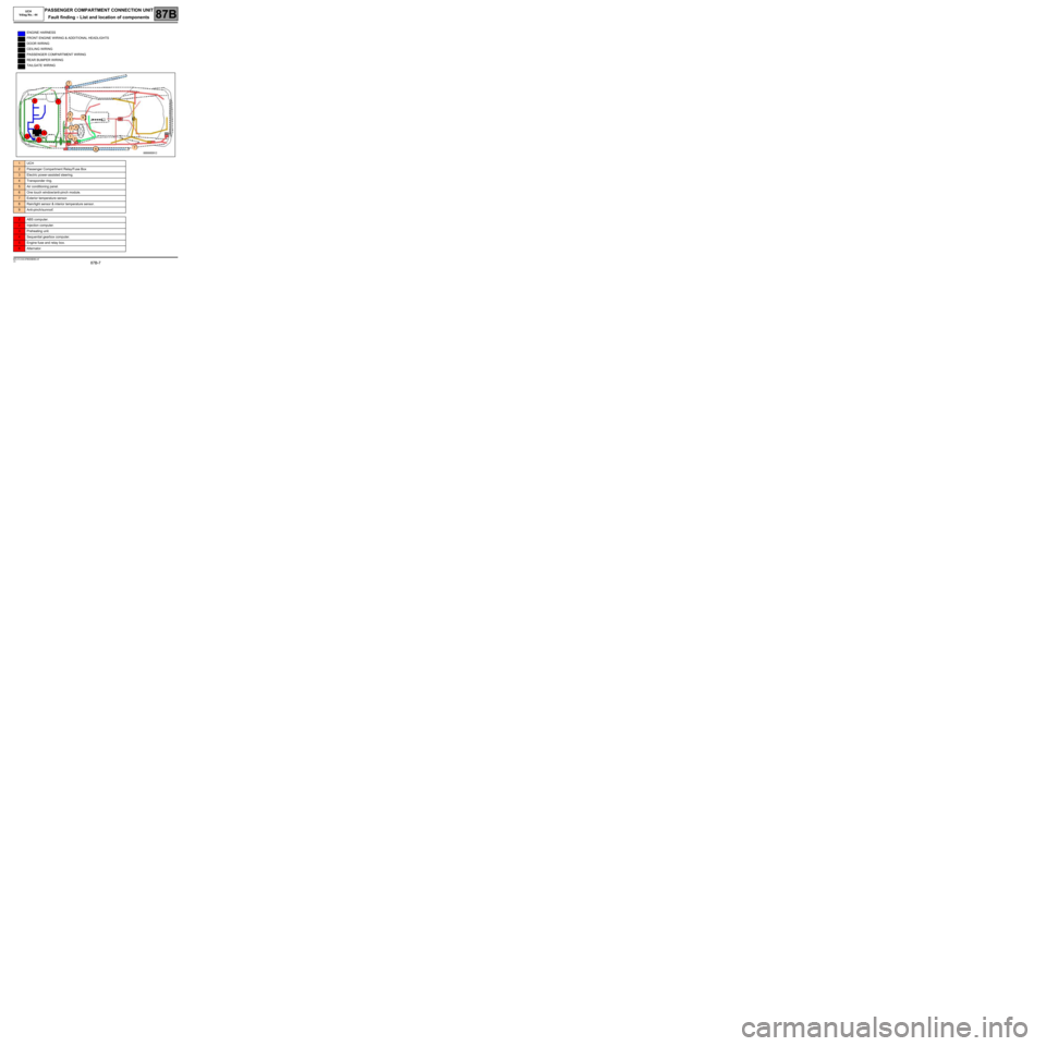
ENGINE HARNESS
FRONT ENGINE WIRING & ADDITIONAL HEADLIGHTS
DOOR WIRING
CEILING WIRING
PASSENGER COMPARTMENT WIRING
REAR BUMPER WIRING
TAILGATE WIRING
1UCH
2Passenger Compartment Relay/Fuse Box
3Electric power-assisted steering.
4Transponder ring.
5Air conditioning panel.
6One touch window/anti-pinch module.
7Exterior temperature sensor.
8Rain/light sensor & interior temperature sensor.
9Anti-pinch/sunroof.
2ABS computer.
2Injection computer.
3Preheating unit.
4Sequential gearbox computer.
5Engine fuse and relay box.
6Alternator.
7
2
61
2
3
5
4
8
5
7
43
1
6
9
PASSENGER COMPARTMENT CONNECTION UNIT
Fault finding
- List and location of components
MR-413-X44-87B000$096.mif
UCH
Vdiag No.: 44
Page 25 of 179
87B-25
MR-413-X44-87B000$384.mif
V5
87B
PASSENGER COMPARTMENT CONNECTION UNIT
Fault finding - Interpretation of faults
DF001
PRESENT
OR
STOREDUCH
1.DEF : Internal electronic fault
NOTESConditions for applying the fault finding procedure to stored faults:
The fault is declared present after the ignition is switched off and back on.
If the fault is stored, clear the fault, switch off the ignition and disconnect the F8 (15A) fuse of the UCH supply
(component code 645) on the passenger compartment fuse and relay box (component code 1016).
–Refit the fuse and switch the ignition back on.
–Request locking and then unlocking, then start the engine.
Check the condition and connection of the PE1, PE2 and PE3 connectors of the UCH (component code 645)
(tabs pushed back, oxidised, broken).
If the connector(s) are faulty and there is a repair procedure (see Technical Note 6015A, Electrical wiring
repair, Wiring: Precautions for repair), repair the wiring, otherwise replace the wiring.
Check for + after ignition feed on connection AP43 of component 645.
Check for + accessories feed on connection SP2 (for vehicles fitted with a manual gearbox) or SP15
(for vehicles fitted with a sequential gearbox) of component 645.
Check for earth on connection NAM of component 645. Check the earth on connection MAM of component 645.
If the connection or connections are faulty and there is a repair procedure (see Technical Note 6015A, Electrical
wiring repair, Wiring: Precautions for repair), repair the wiring, otherwise replace it.
If the fault reappears as stored, contact Techline.
If the fault does not reappear, switch the lighting, wipers, vehicle locking and climate control request controls on
and off several times, then read the faults again.
If the fault is still present. Do not operate on the computer, contact Techline.
AFTER REPAIRIf the computer has been replaced (at the request of the Techline): reconfigure the new
UCH (see Configurations and programming).
Deal with any other faults.
UCH_V44_DF001
MR-413-X44-87B000$384.mif
UCH
Vdiag No.: 44
Page 26 of 179
87B-26
MR-413-X44-87B000$384.mif
V5
PASSENGER COMPARTMENT CONNECTION UNIT
Fault finding - Interpretation of faults
UCH
Vdiag No.: 44
87B
DF011
PRESENT
OR
STOREDRAIN/LIGHT SENSOR CIRCUIT
1.DEF : Open circuit or short circuit
NOTESConditions for applying the fault finding procedure to stored faults:
Switch on the ignition, activate automatic headlighting by quickly performing the
following manipulation twice: control stalk (component code 209) on zero position →
control stalk (component code 209) in Side light position.
Status ET114 “Wiper request by rain sensor” should be “Low speed” or “High
speed” when the water runs over the rain/light sensor on the windscreen or
status ET115 “Request for lights to be switched on by light sensor” should be
“Present” by placing an opaque cover over the rain/light sensor.
Note:
If there is an open circuit on connection BPT, there is a malfunction on the
electric windows, rain/light sensor, interior light(s) and luggage compartment
light.
Check that the vehicle has a rain/light sensor (component code 1415).
Check that the function is not deactivated, quickly perform the following cycle twice to activate the automatic
headlighting function: Monolever (component code 209) OFF → Monolever (component code 209) in Side light
ON position.
Check that the vehicle has a rain/light sensor (component code 1415).
Check that LC044 "Rain/light sensor" displays "Present". If not, carry out CF035 "Rain/light sensor".
Check that LC096 "Automatic wiper function" displays "With". If not, carry out CF194 "Automatic wiper
function".
Check that LC095 "Automatic headlight function", displays "With". If not, carry out CF193 "Automatic
headlight function".
Check the condition and the positioning of fuses F2 (15A), F8 (15A), F19 (5A), F27 (5 A) depending on the
equipment and F29 (15A) on the passenger compartment fuse and relay box (component code 1016).
Replace the fuse(s) or repair if necessary.
Check the condition and connection of the PE1, PE2 and PE3 connectors of the UCH (component code 645)
(tabs pushed back, oxidised, broken).
Check for + after ignition feed on connection AP43 of component 645.
Check for + accessories feed on connection SP2 (for vehicles fitted with a manual gearbox) or SP15
(for vehicles fitted with a sequential gearbox) of component 645.
Check for earth on connection NAM of component 645. Check the earth on connection MAM of component 645.
If the connection or connections are faulty and there is a repair procedure (see Technical Note 6015A, Electrical
wiring repair, Wiring: Precautions for repair), repair the wiring, otherwise replace it.
AFTER REPAIRCarry out another fault finding check on the system.
Clear the stored faults.
Deal with any other faults.
UCH_V44_DF011
Page 58 of 179
87B-58
MR-413-X44-87B000$432.mif
V5
PASSENGER COMPARTMENT CONNECTION UNIT
Fault finding - Interpretation of faults
UCH
Vdiag No.: 44
87B
DF133
CONTINUED 1
When unlocking, check the signal status on components 140 and 141 of the following connections using an
oscilloscope (refer to test2 Central door unlocking).
Right or left-hand door locks:
Oscilloscope red test pin on connection 20D of component 140 or 141.
Oscilloscope black test pin on connection 20C of component 140 or 141.
If the connection or connections are faulty and there is a repair procedure (see Technical Note 6015A, Electrical
wiring repair, Wiring: Precautions for repair), repair the wiring, otherwise replace it.
Central door deadlocking check:
Check the insulation, continuity and the absence of interference resistance of the following connections:
●Connection code 20C between components 140 or 141 and 645.
●Connection code 20D between components 140 or 141 and 645.
●Connection code 20AP (specific to deadlocking) between components 140 or 141 and 1042.
●Connection code MAN between component 140 and earth MAN (for left-hand drive vehicles) and connection
code MAM between component 141 and earth MAM (for right-hand drive vehicles).
For manual gearbox:
●Connection code 86H between components 140 or 141 and 1016.
For sequential gearbox:
●Connection code H24 between components 140 and 1016.
If the connection or connections are faulty and there is a repair procedure (see Technical Note 6015A, Electrical
wiring repair, Wiring: Precautions for repair), repair the wiring, otherwise replace it.
Central door locking relay check (for deadlocking):
Check the insulation, continuity and the absence of interference resistance of the following connections:
●Connection code BP3 between components 1042 and 1016.
●Connection code MAM between component 1042 and earth MAM.
●Connection code 20AP between components 1042 and 645.
If the connection or connections are faulty and there is a repair procedure (see Technical Note 6015A, Electrical
wiring repair, Wiring: Precautions for repair), repair the wiring, otherwise replace it.
If the supply and the earth of the central door locking relay (specific to deadlocking) are correct, replace the
relay.
AFTER REPAIRCarry out another fault finding check on the system.
Clear the stored faults.
Deal with any other faults.
Page 140 of 179
87B -140
MR-413-X44-87B000$624.mif
V5
PASSENGER COMPARTMENT CONNECTION UNIT
Fault finding - Interpretation of statuses
UCH
Vdiag No.: 44
87B
ET463
CONTINUED 1
Tailgate locks:
Check for + 12 V on connection 86H (when there is an opening request) of component 1322. Check for earth on
connection MYH on component 1322.
Electric central door locking, tailgate lock and central door locking relay check:
Check the insulation, continuity and the absence of interference resistance of the following connections:
Door locks:
●Connection code 20C between components 140 or 141 and 645.
●Connection code 20D between components 140 or 141 and 645.
●Connection code 20AP between components 140 or 141 and 1016.
●Connection code MAN (right-hand drive) or MAM (left-hand drive) between component 140 and earth
MAN (right hand drive) or MAM (left-hand drive).
●Connection code MAN (left-hand drive) or MAM (right-hand drive) between component 141 and earth
MAN (left-hand drive) or MAM (right-hand drive).
Tailgate lock:
●Connection code 20S between components 1322 or 645.
●Connection code 86H between components 1322 or 645.
●Connection code MYH between component 1322 and earth MYH.
For manual gearbox:
●Connection code 86H between components 140 or 141 and 645.
For sequential gearbox:
●Connection code H24 between components 140 and 645.
If the connection or connections are faulty and there is a repair procedure (see Technical Note 6015A, Electrical
wiring repair, Wiring: Precautions for repair), repair the wiring, otherwise replace it.
If the supplies and connections of the electric central door and tailgate locking are correct, check the central door
locking relay.
Check the insulation of the contact of component 140 between connections 86H and MAM (door closed).
Check the continuity of the contact of component 140 between connections 86H and MAM (door open).
Check the insulation of the contact of component 141 between connections 86H and MAM (door closed).
Check the continuity of the contact of component 141 between connections 86H and MAM (door open).
If the connection or connections are faulty and there is a repair procedure (see Technical Note 6015A, Electrical
wiring repair, Wiring: Precautions for repair), repair the wiring, otherwise replace it.
If the supply, connections and earth of the central door locking relay are correct, replace the relay.
If the supplies, central door locking connections, locking relay and electric central door locking relay are correct,
replace the lock concerned.
AFTER REPAIRRepeat the conformity check from the start.
Carry out fault finding on the system.
Page 154 of 179
87B -154
MR-413-X44-87B000$816.mif
V5
PASSENGER COMPARTMENT CONNECTION UNIT
Fault finding - Interpretation of commands
UCH
Vdiag No.: 44
87B
AC004
AC005
CONTINUED 2
Checking the electric central door locking, tailgate lock and central door locking relay (component code
1322):
Check the insulation, continuity and the absence of interference resistance on the following connections:
Door locks:
●Connection code 20C between components 140 or 141 and 645.
●Connection code 20D between components 140 or 141 and 645.
●Connection code 20AP between components 140 or 141 and 1042 (if deadlocking).
●Connection code MAN (right-hand motor) or MAM (left-hand motor) between component 140 or 141 and
the earth MAN (right-hand motor) or MAM (left-hand motor).
Tailgate lock check:
●Connection code 20S between components 1322 or 645.
●Connection code 86H between components 1322 or 645.
●Connection code MYH between component 1322 and earth MYH.
For manual gearbox:
●Connection code 86H between components 140 or 141 and 1016.
For sequential gearbox:
●Connection code H24 between components 140 and 1016.
If the connection or connections are faulty and there is a repair procedure (see Technical Note 6015A, Electrical
wiring repair, Wiring: Precautions for repair), repair the wiring, otherwise replace it.
Vehicle which is equipped with deadlocking function:
If the supplies and connections of the electric central door and tailgate locking are correct, check the central door
locking relay (Component code 1042).
Check the insulation, continuity and the absence of interference resistance on the following connections:
Central door locking relay check:
●Connection code BP3 between components 1042 and 1016.
●Connection code MAM between component 1042 and earth MAM.
●Connection code 20AP between components 1042 and 645.
If the connection or connections are faulty and there is a repair procedure (see Technical Note 6015A, Electrical
wiring repair, Wiring: Precautions for repair), repair the wiring, otherwise replace it.
If the supply, connections and earth of the central door locking relay are correct, replace the relay.
If the feeds, the electric door locking connections, the locking relay (Connection code 1042) and the electric
central door locking are correct, check the door lock switch / hazard warning light switch (component
code 1391).
AFTER REPAIRCarry out another fault finding check on the system.
Page 169 of 179
87B -169
MR-413-X44-87B000$912.mif
V5
PASSENGER COMPARTMENT CONNECTION UNIT
Fault finding - Fault Finding Chart
UCH
Vdiag No.: 44
87B
ALP 26 Accessories feed not activated
NOTESCheck the battery voltage (see 80A Battery).
Start the fault finding procedure with the ignition off and the vehicle locked.
When the vehicle is unlocked, the instrument panel should light up for a moment.
Otherwise, carry out fault finding on the multiplex network (see 88B, Multiplexing).
Check the operation of status ET239 "Ignition switch position".
Check the presence and condition of fuses F27 (5 A), depending on the equipment, and F29 (15 A) on the
passenger compartment fuse and relay box (component code 1016).
Replace the fuse if necessary.
Check the condition and connection of the connectors of components 645 and 1016 (tabs bent, oxidised or
broken).
Check for + accessories feed on connection SP2 (for vehicles fitted with a manual gearbox) or SP15 (for
vehicles fitted with a sequential gearbox) of component 645.
Check for earth on connection NAM of component 645.
Check for earth on the connection MAM (for right-hand drive vehicles) or MAN (for left-hand drive vehicles) of
component 645.
If the connection or connections are faulty and there is a repair procedure (see Technical Note 6015A, Electrical
wiring repair, Wiring: Precautions for repair), repair the wiring, otherwise replace it.
Check the insulation, continuity and the absence of interference resistance of the following connections:
Connection code SP2 between components 645 and 1016.
Connection code SP15 between components 645 and 1016.
Connection code MAN or MAM between component 645 and earth MAN or MAM (depending on the driving
layout; right-hand or left-hand drive).
If the connection or connections are faulty and there is a repair procedure (see Technical Note 6015A, Electrical
wiring repair, Wiring: Precautions for repair), repair the wiring, otherwise replace it.
If the fault is still present, contact the Techline.
AFTER REPAIRCarry out a complete check using the diagnostic tool.
UCH_V44_ALP26