Injector rail RENAULT TWINGO 2009 2.G Engine And Peripherals Owner's Manual
[x] Cancel search | Manufacturer: RENAULT, Model Year: 2009, Model line: TWINGO, Model: RENAULT TWINGO 2009 2.GPages: 652
Page 355 of 652
13A-12
FUEL SUPPLY
Fuel pressure: Check
K4M
13A
CHECK
aI - PREPARATION OPERATION FOR CHECK
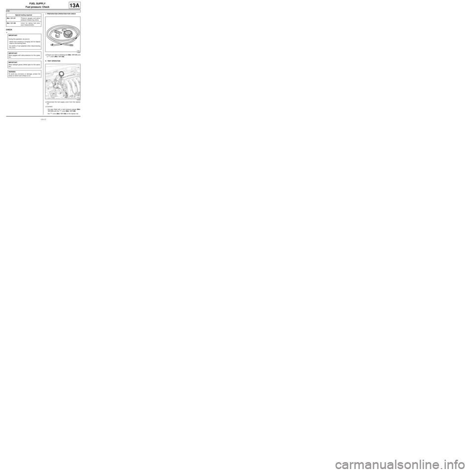
aEnsure you have a checking tool (Mot. 1311-01) and
a “T” union (Mot. 1311-08).
II - TEST OPERATION
aDisconnect the fuel supply union from the injector
rail.
aConnect:
-the pipe fitted with a test pressure gauge (Mot.
1311-01) with the "T" union (Mot. 1311-08),
-the "T" union (Mot. 1311-08) on the injector rail, Special tooling required
Mot. 1311-01Pressure gauges and petrol
pressure measur ing unions.
Mot. 1311-08Union for taking fuel pres-
sure measurements .
IMPORTANT
During this operation, be sure to:
-refrain from smoking or bringing red hot objects
close to the working area,
-be careful of fuel splashes when disconnecting
the union.
IMPORTANT
Wear goggles with side protectors for this opera-
tion.
IMPORTANT
Wear leaktight gloves (Nitrile type) for this opera-
tion.
WARNING
To avoid any corrosion or damage, protect the
areas on which fuel is likely to run.
116887
132333
Page 356 of 652
13A-13
FUEL SUPPLY
Fuel pressure: Check
K4M
13A
-the injector rail fuel supply union to the "T" union
(Mot. 1311-08).
aStart the engine.
aRecord the pressure; this should be constant at 3.5
bar.
aSwitch off the engine.
III - FINAL OPERATION
aDisconnect the "T" union (Mot. 1311-08) from the in-
jector rail.
aConnect the fuel supply pipe union on the injector
rail.Note:
It may take a few seconds to obtain a correct
injector rail pressure reading.
Page 360 of 652
13A-17
FUEL SUPPLY
Fuel flow: Check
K4M
13A
I - PREPARATION OPERATION FOR CHECK
aEnsure you have a checking tool (Mot. 1311-01) and
a “T” union (Mot. 1311-08).
aAssemble the long hose of the test tool (Mot. 1311-
01) and the "T" union (Mot. 1311-08).
aDisconnect the fuel supply union on the injector rail.aConnect:
-the "T" union (Mot. 1311-08) on the injector rail,
-the fuel supply union to the "T" union (Mot. 1311-
08).
II - FUEL FLOW CHECK
aImmerse the hose in a 2000 ml graduated measur-
ing cylinder.
aRemove the cover from the engine compartment
connection unit. Special tooling required
Mot. 1311-01Pressure gauges and petrol
pressure measur ing unions.
Mot. 1311-08Union for taking fuel pres-
sure measurements .
Equipment required
graduated measuring cylinder
IMPORTANT
During this oper ation, be sure to:
-refrain from smoking or bringing red hot objects
close to the working area,
-be careful of fuel splashes when disconnecting the
union.
IMPORTANT
Wear leaktight gloves (Nitrile type) for this opera-
tion.
IMPORTANT
Wear goggles with side protectors for this opera-
tion.
WARNING
To avoid any corrosion or damage, protect the
areas on which fuel is likely to run.
132334
Page 361 of 652
13A-18
FUEL SUPPLY
Fuel flow: Check
K4M
13A
aRemove the relay (1) .
aShunt the relay in order to supply the electric fuel
pump.
III - FINAL OPERATION
aRefit:
-the relay,
-the engine compartment connection unit cover.
aDisconnect:
-the fuel supply union on the "T" union (Mot. 1311-
08),
-the "T" union (Mot. 1311-08) from the injector rail.
aConnect the fuel supply union on the injector rail.
aSeparate the test tool (Mot. 1311-01) from the "T"
union (Mot. 1311-08).
119373
Note:
The flow reading should be 80 to 120 l/h.
Page 369 of 652
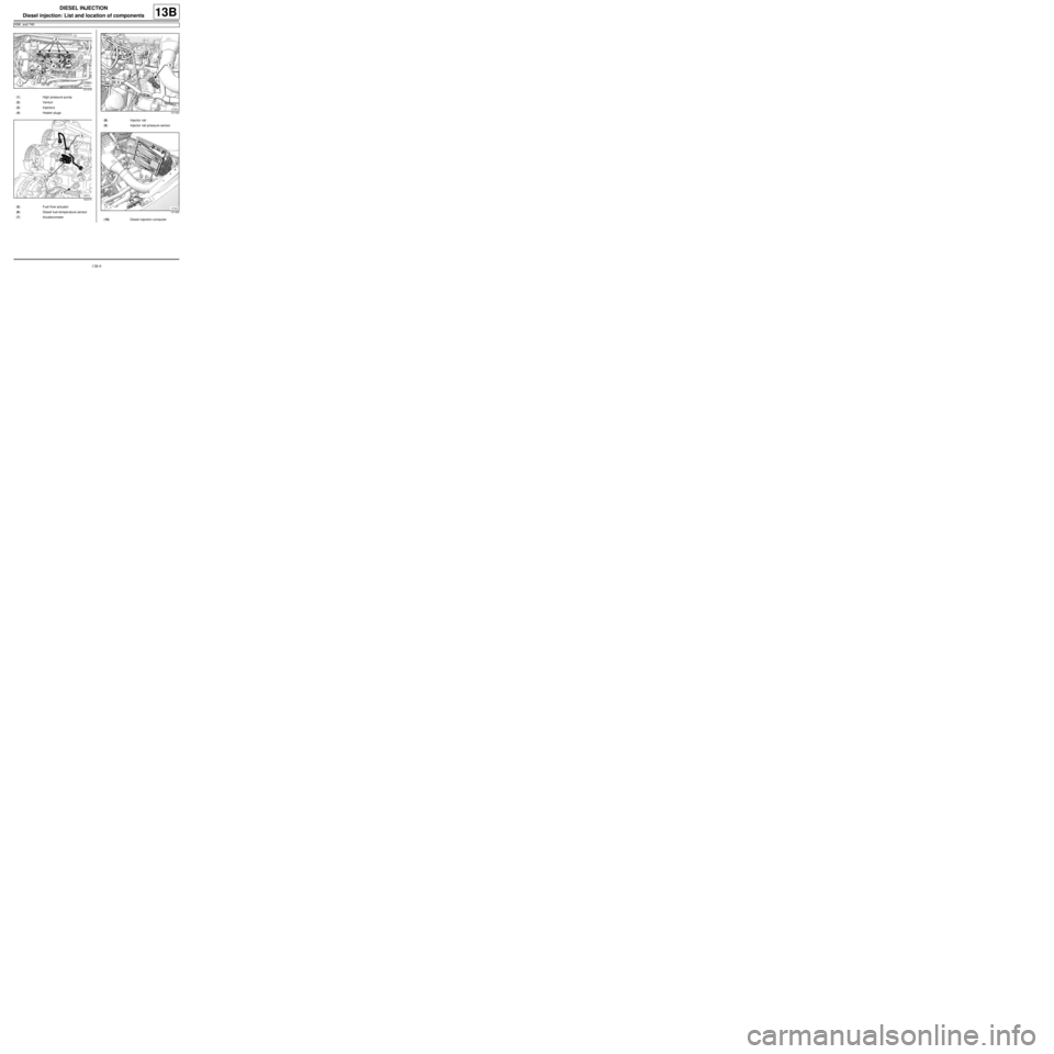
13B-8
DIESEL INJECTION
Diesel injection: List and location of components
K9K, and 740
13B
121418
(1) High pressure pump
(2) Venturi
(3) Injectors
(4) Heater plugs
102315
(5) Fuel fl ow actuator
(6) Diesel fuel temperature sensor
(7) Accelerometer
121420
(8) Injector rail
(9) Injector rail pressure sensor
121422
(10) Diesel injection computer
Page 371 of 652
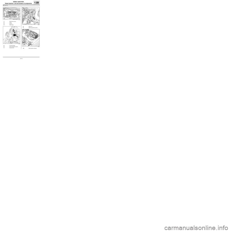
13B-10
DIESEL INJECTION
Diesel injection: List and location of components
K9K, and 718
13B
121418
(1) High pressure pump
(2) Venturi
(3) Injectors
(4) Heater plugs
102315
(5) Fuel fl ow actuator
(6) Diesel temperature sensor
(7) Accelerometer
121420
(8) Injector rail
(9) Injector rail pressure sensor
121422
(10) Diesel injection computer
Page 385 of 652
13B-24
DIESEL INJECTION
High pressure pump: Removal - Refitting
K9K
13B
aRefit the lower timing cover.
aRefit the accessories belt (see 11A, Top and front
of engine, Accessories belt: Removal - Refitting,
page 11A-3)
aRefit:
-the upper timing cover,
-the camshaft position sensor (see 13B, Diesel in-
jection, Camshaft position sensor: Removal -
Refitting, page 13B-14) ,
-the right-hand suspended engine mounting (see
19D, Engine mounting, Right-hand suspended
engine mounting: Removal - Refitting, page
19D-13) .
aRemove the blanking plugs.
aRefit a high pressure pipe between the pump and
the rail (see 13B, Diesel injection, High pressure
pipe between pump and rail: Removal - Refitting,
page 13B-35) .
aConnect the diesel return pipe to the venturi fitted to
the high pressure pump.aRefit:
-the fuel filter mounting,
-the fuel filter (see 13A, Fuel supply, Fuel filter:
Removal - Refitting, page 13A-4) .
aRefit:
-the engine tie-bar (see 19D, Engine mounting,
Lower engine tie-bar: Removal - Refitting, page
19D-18) ,
-the engine harness channel.
aFit the engine wiring on the engine wiring channel.
aClip on the engine wiring channel.
aConnect to the high pressure pump:
-the diesel supply pipe,
-the diesel return pipe to the diesel filter.
aClip on the high pressure pump pipes.
aRemove the protection on the alternator to prevent
fuel flowing out.
aConnect the connectors of:
-the diesel temperature sensor,
-the flow actuator,
-the injectors,
-the heater plugs.
aRemove the blanking cover which protects the oil
level dipstick guide inlet opening on the cylinder
block.
aRefit:
-the dipstick guide,
-the dipstick,
-the scoop under the scuttle panel grille (see Scoop
under the scuttle panel grille: Removal - Refit-
ting) (56A, Exterior equipment),
-the scuttle panel grille (see Scuttle panel grille:
Removal - Refitting) (56A, Exterior equipment),
-the windscreen wiper arms (see Windscreen wip-
er arm: Removal - Refitting) (85A, Wiping -
Washing).
aPrime the fuel circuit with a manual priming pump
until the disconnected pipes are filled with fuel; if
necessary, bleed the fuel filter (see 13A, Fuel sup-
ply, Fuel filter: Removal - Refitting, page 13A-4) .
aCheck that there are no fuel leaks.
aConnect the battery (see ) (80A, Battery). K9K, and 740
19659
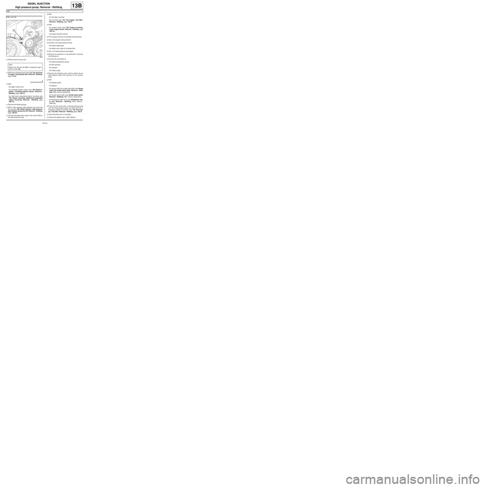
Note:
Make sure that the tab (23) is positioned oppo-
site the mark (24) .
Page 387 of 652
13B-26
DIESEL INJECTION
Flow actuator: Removal - Refitting
K9K
13B
PIECES ET INGREDIENTS POUR LA REPARATION
Pièces à remplacer systématiquement :
-the high pressure pipe between the rail and injector
number 4,
-the clip between high pressure pipes number 3 and 4.
Ingrédients :
-cleaning cloths,
-set of K9K blanking plugs (injection DELPHI).
REMOVAL
I - REMOVAL PREPARATION OPERATION
aDisconnect the battery (see ) (MR 411, 80A, Bat-
tery).
aRemove the front engine cover.aRemove:
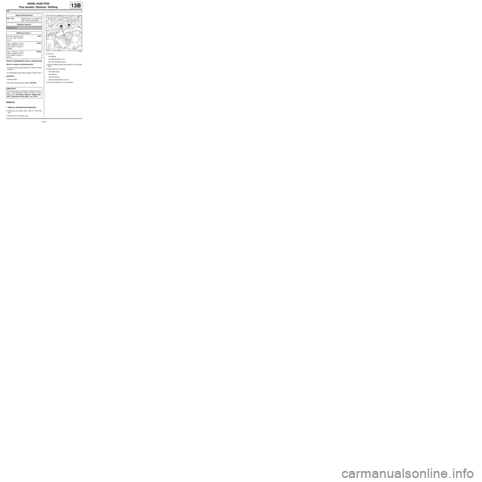
-the dipstick,
-the dipstick guide nut (1) ,
-the oil level dipstick guide.
aBlock the dipstick guide inlet opening on the cylinder
block.
aDisconnect the connectors:
-the heater plugs,
-the injectors,
-the flow actuator,
-diesel fuel temperature sensor.
aProtect the alternator from fuel outflow. Special tooling required
Mot. 1746Offset wrench for tightening
High Pressure pump pipes.
Equipment required
Diagnostic tool
Tightening torquesm
fuel flow actuator bolts
on the high pressure
pump6 Nm
high pressure pipe
unions between the rail
and injector number 4
(yellow)24 Nm
high pressure pipe
unions between the rail
and injector number 4
(silver)28 Nm
IMPORTANT
Consult the safety and cleanliness advice and oper-
ation recommendations before carrying out any
repair (see 13B, Diesel injection, Diesel injec-
tion: Precautions for the repair, page 13B-1) .
114527
Page 388 of 652

13B-27
DIESEL INJECTION
Flow actuator: Removal - Refitting
K9K
13B
aClean the diesel pipe unions on the high pressure
pump (see 13B, Diesel injection, Diesel injection:
Precautions for the repair, page 13B-1) .
aUnclip the fuel supply pipes at (2) .
aDisconnect the high pressure pump from:
-the diesel supply pipe (3) ,
-the diesel return pipe (4) to the diesel filter.
aRemove the high pressure pump pipes.aUnclip the neck at (5) .
aRemove the neck wiring harness.
aRemove:
-the neck nut (6) ,
-the neck.
aClean the high pressure pipe unions (7) between the
rail and injector number 4 (see 13B, Diesel injec-
tion, Diesel injection: Precautions for the repair,
page 13B-1) .
121423
WARNING
To avoid any corrosion or damage, protect the
areas on which fuel is likely to run.
WARNING
To prevent impurities from entering the circuit,
plugs must be fitted to the openings of all the fuel
circuit components exposed to the open air.121419
121418
WARNING
To avoid any corrosion or damage, protect the
areas on which fuel is likely to r un.
Page 389 of 652
13B-28
DIESEL INJECTION
Flow actuator: Removal - Refitting
K9K
13B
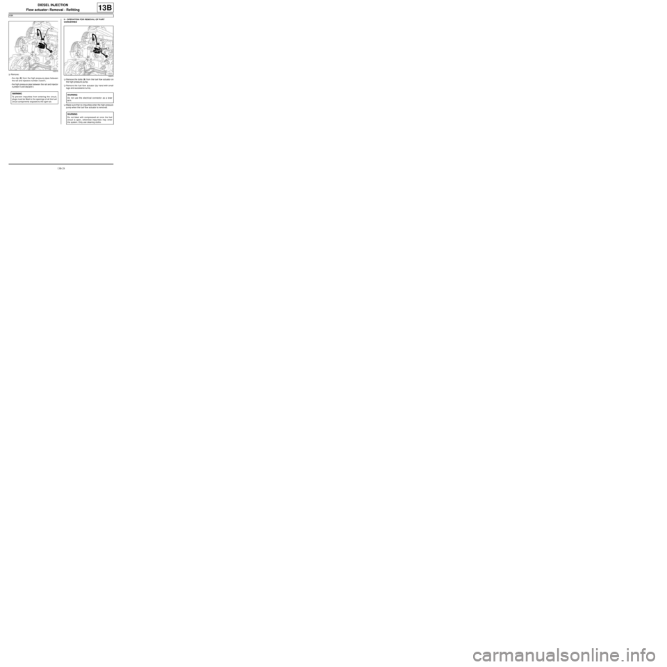
aRemove:
-the clip (8) from the high pressure pipes between
the rail and injectors number 3 and 4,
-the high pressure pipe between the rail and injector
number 4 and discard it.II - OPERATION FOR REMOVAL OF PART
CONCERNED
aRemove the bolts (9) from the fuel flow actuator on
the high pressure pump.
aRemove the fuel flow actuator (by hand with small
tugs and successive turns).
aMake sure that no impurities enter the high pressure
pump when the fuel flow actuator is removed.
102315
WARNING
To prevent impurities from entering the circuit,
plugs must be fitted to the openings of all the fuel
circuit components exposed to the open air.
102315
WARNING
Do not use the electr ical connector as a lever
ar m.
WARNING
Do not blast with compressed air once the fuel
circuit is open, otherwise impurities may enter
the system. Only use cleaning cloths.