Injector rail RENAULT TWINGO 2009 2.G Engine And Peripherals Repair Manual
[x] Cancel search | Manufacturer: RENAULT, Model Year: 2009, Model line: TWINGO, Model: RENAULT TWINGO 2009 2.GPages: 652
Page 503 of 652
17B-28
PETROL INJECTION
Injector rail - Injectors: Removal - Refitting
D4F, and 772
17B
-the injectors (3) .
REFITTING
I - REFITTING OPERATION FOR PART
CONCERNED
aRefit:
-the injectors,
-the injector clips,
-the injector wiring harness,
-the injector rail,
-the injector rail bolts.
aConnect the injector wiring harness.
II - FINAL OPERATION.
aRefit:
-the intake distributor (see 12A, Fuel mixture, Inlet
distributor: Removal - Refitting, page 12A-29) ,
-the air filter box (see 12A, Fuel mixture, Air filter
unit: Removal - Refitting, page 12A-13) .
aConnect the battery (see Battery: Removal - Refit-
ting) ).
Page 504 of 652
17B-29
PETROL INJECTION
Injector rail - Injectors: Removal - Refitting
D4F, and 780 or 782
17B
REMOVAL
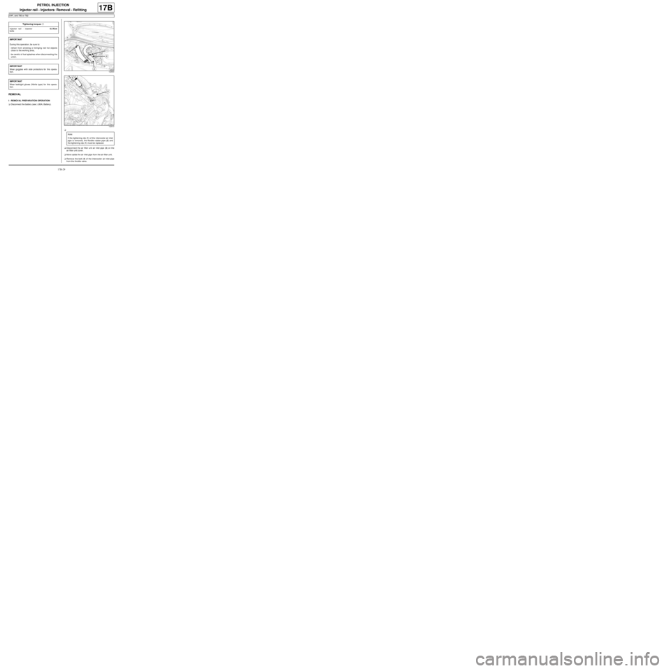
I - REMOVAL PREPARATION OPERATION
aDisconnect the battery (see ) (80A, Battery).
a
aDisconnect the air filter unit air inlet pipe (3) on the
air filter unit cover.
aMove aside the air inlet pipe from the air filter unit.
aRemove the bolt (4) of the intercooler air inlet pipe
from the throttle valve. Tightening torquesm
injector rail - injector
bolts4.5 N.m
IMPORTANT
During this oper ation, be sure to:
-refrain from smoking or bringing red hot objects
close to the working area,
-be careful of fuel splashes when disconnecting the
union.
IMPORTANT
Wear goggles with side protectors for this opera-
tion.
IMPORTANT
Wear leaktight gloves (Nitrile type) for this opera-
tion.
122833
122673
Note:
If the tightening clip (1) of the intercooler air inlet
pipe is removed, the flexible rubber pipe (2) and
the tightening clip (1) must be replaced.
Page 505 of 652

17B-30
PETROL INJECTION
Injector rail - Injectors: Removal - Refitting
D4F, and 780 or 782
17B
aUnclip the intercooler air inlet pipe from the turbo-
charger in the direction of the arrow (5) .
aDisconnect the intercooler air inlet pipe from the tur-
bocharger.
aMove aside the intercooler air inlet pipe.
aDisconnect the petrol vapour rebreathing pipe from:
-the inlet distributor (7) ,
-the air filter unit air outlet pipe (8) .
aUnclip the petrol vapour rebreathing pipe.
aRemove the petrol vapour rebreathing pipe.Note:
If the clip (6) is removed from the heat resistant
protector, the latter must be replaced.
122389
Page 506 of 652
17B-31
PETROL INJECTION
Injector rail - Injectors: Removal - Refitting
D4F, and 780 or 782
17B
II - OPERATION FOR REMOVAL OF PART
CONCERNED
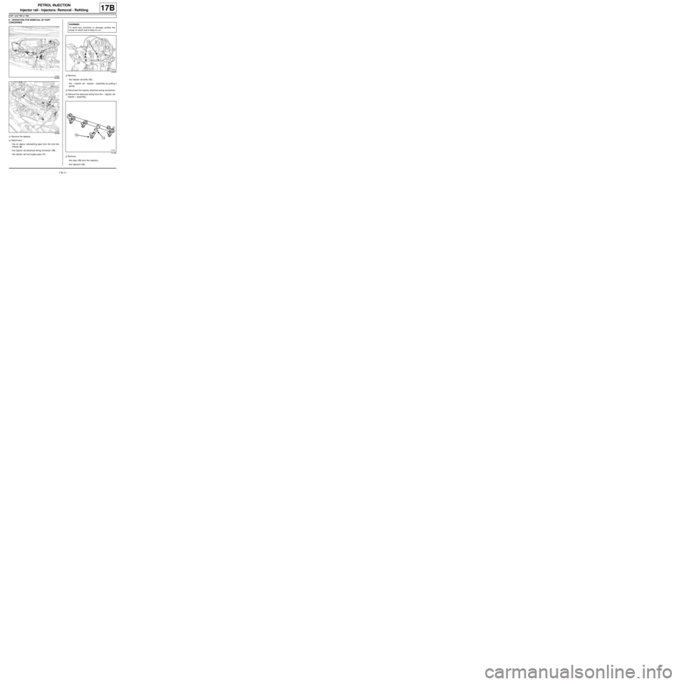
aRemove the dipstick.
aDisconnect:
-the oil vapour rebreathing pipe from the inlet dis-
tributor (9) ,
-the injector rail electrical wiring connector (10) ,
-the injector rail fuel supply pipe (11) .aRemove:
-the injector rail bolts (12) ,
-the « injector rail - injector » assembly by pulling it
gently.
aDisconnect the injector electrical wiring connectors.
aRemove the electrical wiring from the « injector rail -
injector » assembly.
aRemove:
-the clips (13) from the injectors,
-the injectors (14) .
122389
122388
WARNING
To avoid any corrosion or damage, protect the
areas on which fuel is likely to r un.
120955
101492
Page 507 of 652
17B-32
PETROL INJECTION
Injector rail - Injectors: Removal - Refitting
D4F, and 780 or 782
17B
REFITTING
I - REFITTING PREPARATION OPERATION
aparts always to be replaced: injector clip on in-
jector rail.
aparts always to be replaced: injector seal.
II - REFITTING OPERATION FOR PART
CONCERNED
aRefit:
-the injectors with new seals,
-new clips on the injectors,
-the injector rail - injector electrical wiring.
aConnect the connectors of the electrical wiring to the
injectors.
aRefit:
-the « injector rail - injector » assembly,
-the « injector rail - injector » assembly bolts.
aTorque tighten the injector rail - injector bolts (4.5
N.m).
aConnect:
-the fuel supply pipe on the injector rail,
-the electrical wiring connector to the injector rail,
-the oil vapour rebreathing pipe on the inlet distribu-
tor.
aRefit the dipstick.
III - FINAL OPERATION
aFit the petrol vapour rebreathing pipe.
aClip on the petrol vapour rebreathing pipe.
aConnect the petrol vapour rebreathing pipe to:
-the air outlet pipe of the air filter unit,
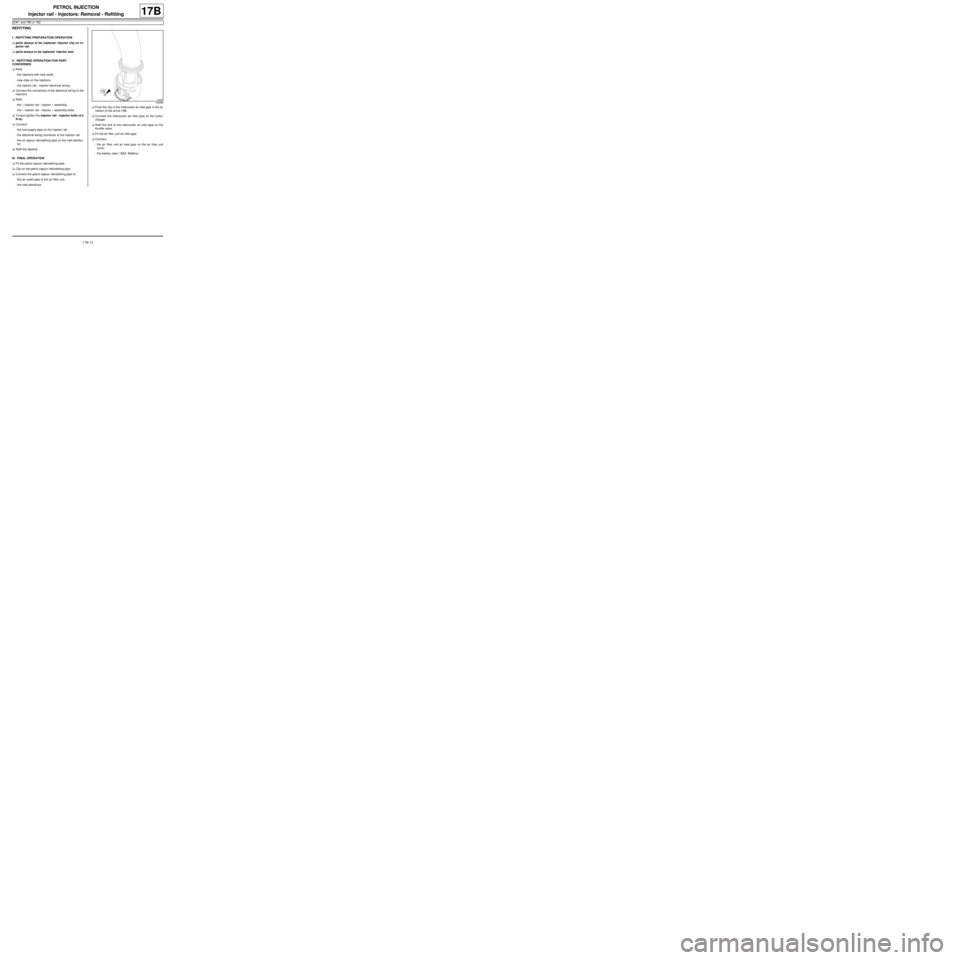
-the inlet distributor.aPush the clip of the intercooler air inlet pipe in the di-
rection of the arrow (15) .
aConnect the intercooler air inlet pipe on the turbo-
charger.
aRefit the bolt of the intercooler air inlet pipe on the
throttle valve.
aFit the air filter unit air inlet pipe.
aConnect:
-the air filter unit air inlet pipe on the air filter unit
cover,
-the battery (see ) (80A, Battery).
122666
Page 508 of 652
17B-33
PETROL INJECTION
Injector rail - Injectors: Removal - Refitting
K4M
17B
REMOVAL
I - REMOVAL PREPARATION OPERATION
aDisconnect the battery (see ) (80A, Battery).
aRemove:
-the windscreen wiper arms (see Windscreen wip-
er arm: Removal - Refitting) (85A, Wiping -
Washing),
-the scuttle panel grille (see Scuttle panel grille:
Removal - Refitting) (56A, Exterior equipment),
-the scoop under the scuttle panel grille (see Scoop
under the scuttle panel grille: Removal - Refit-
ting) (56A, Exterior equipment).a
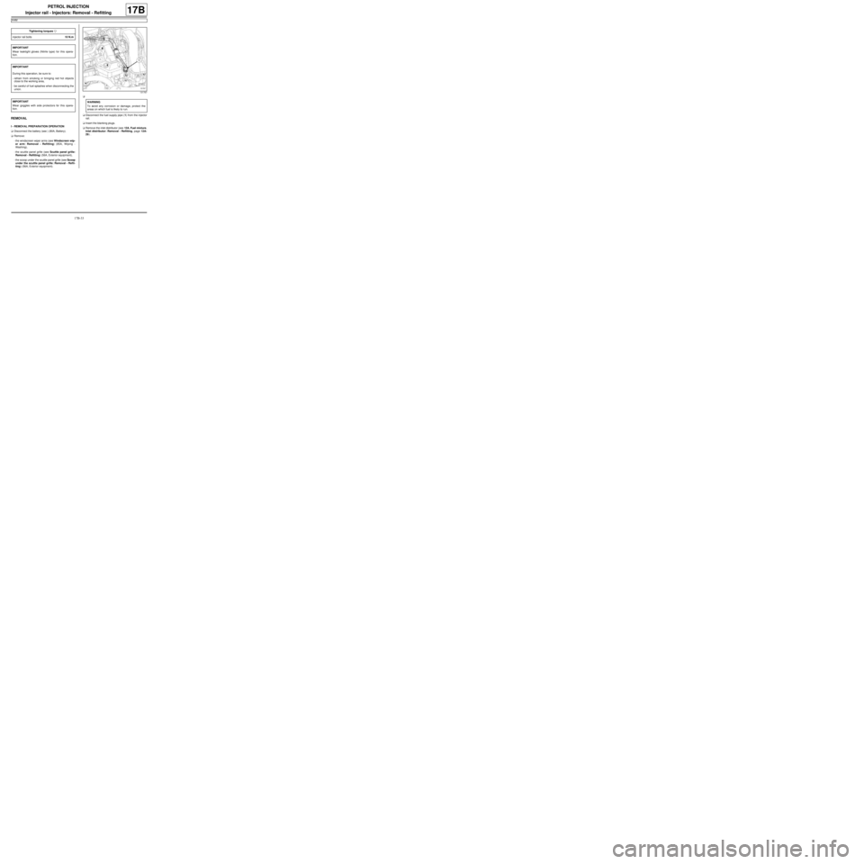
aDisconnect the fuel supply pipe (1) from the injector
rail.
aInsert the blanking plugs.
aRemove the inlet distributor (see 12A, Fuel mixture,
Inlet distributor: Removal - Refitting, page 12A-
29) . Tightening torquesm
injector rail bolts10 N.m
IMPORTANT
Wear leaktight gloves (Nitrile type) for this opera-
tion.
IMPORTANT
During this oper ation, be sure to:
-refrain from smoking or bringing red hot objects
close to the working area,
-be careful of fuel splashes when disconnecting the
union.
IMPORTANT
Wear goggles with side protectors for this opera-
tion.
131767
WARNING
To avoid any corrosion or damage, protect the
areas on which fuel is likely to r un.
Page 509 of 652
17B-34
PETROL INJECTION
Injector rail - Injectors: Removal - Refitting
K4M
17B
II - REMOVAL OPERATION
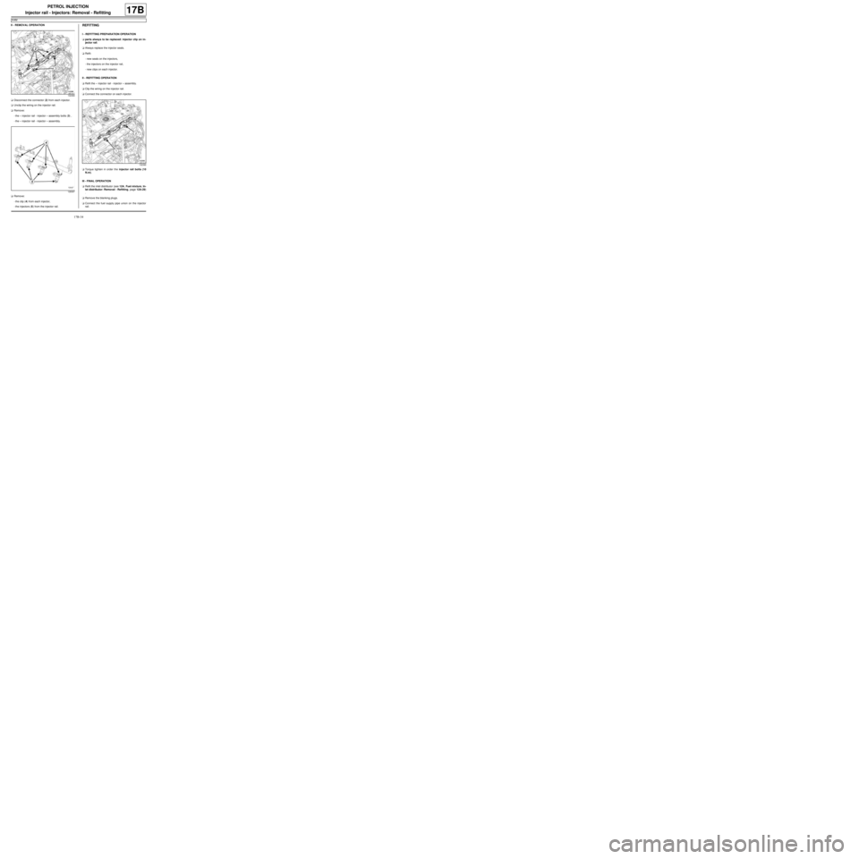
aDisconnect the connector (2) from each injector.
aUnclip the wiring on the injector rail.
aRemove:
-the « injector rail - injector » assembly bolts (3) ,
-the « injector rail - injector » assembly.
aRemove:
-the clip (4) from each injector,
-the injectors (5) from the injector rail.REFITTING
I - REFITTING PREPARATION OPERATION
aparts always to be replaced: injector clip on in-
jector rail.
aAlways replace the injector seals.
aRefit:
-new seals on the injectors,
-the injectors on the injector rail,
-new clips on each injector.
II - REFITTING OPERATION
aRefit the « injector rail - injector » assembly.
aClip the wiring on the injector rail.
aConnect the connector on each injector.
aTorque tighten in order the injector rail bolts (10
N.m).
III - FINAL OPERATION
aRefit the inlet distributor (see 12A, Fuel mixture, In-
let distributor: Removal - Refitting, page 12A-29)
.
aRemove the blanking plugs.
aConnect the fuel supply pipe union on the injector
rail.
132390
128397
132390
Page 510 of 652
17B-35
PETROL INJECTION
Injector rail - Injectors: Removal - Refitting
K4M
17B
aRefit:
-the scoop under the scuttle panel grille (see Scoop
under the scuttle panel grille: Removal - Refit-
ting) (56A, Exterior equipment),
-the scuttle panel grille (see Scuttle panel grille:
Removal - Refitting) (56A, Exterior equipment),
-the windscreen wiper arms (see Windscreen wip-
er arm: Removal - Refitting) (85A, Wiping -
Washing).
aConnect the battery (see ) (80A, Battery).
Page 616 of 652
19C-2
TANK
Fuel tank: Draining
D4F or D7F or K4M
19C
I - DRAINING PREPARATION OPERATION
aDisconnect the battery (see ) (80A, Battery).
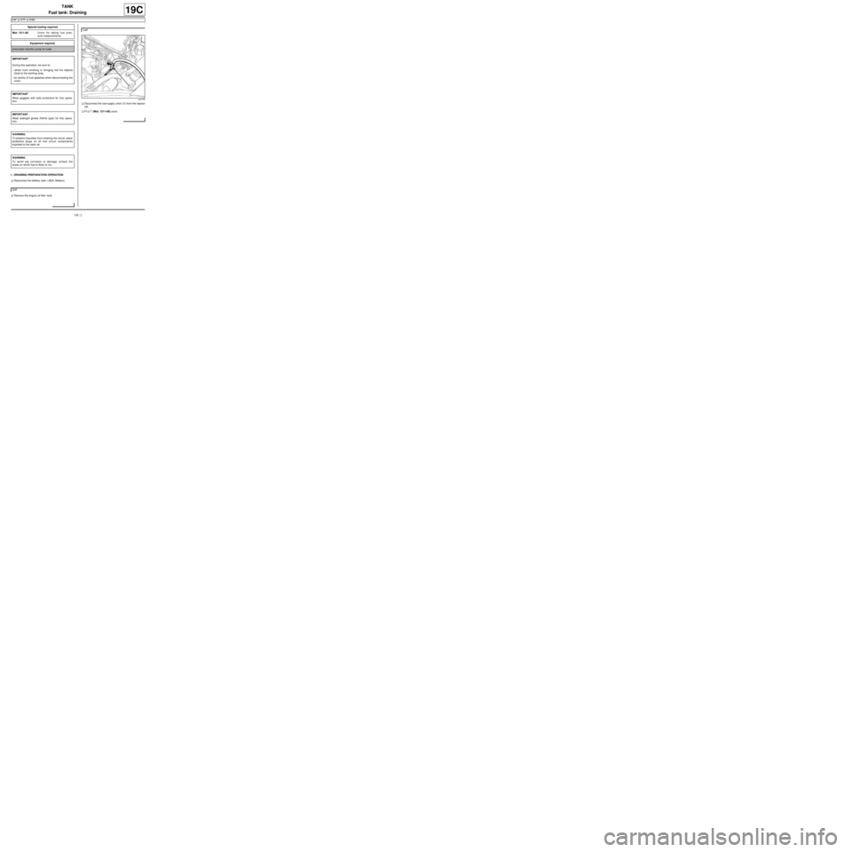
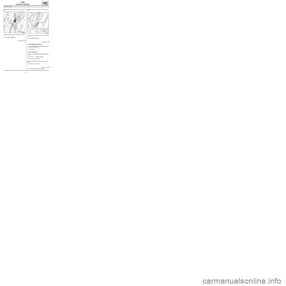
aRemove the engine oil filler neck.aDisconnect the fuel supply union (1) from the injector
rail.
aFit a T (Mot. 1311-08) union. Special tooling required
Mot. 1311-08Union for taking fuel pres-
sure measurements .
Equipment required
pneumatic transfer pump for fuels
IMPORTANT
During this oper ation, be sure to:
-refrain from smoking or bringing red hot objects
close to the working area,
-be careful of fuel splashes when disconnecting the
union.
IMPORTANT
Wear goggles with side protectors for this opera-
tion.
IMPORTANT
Wear leaktight gloves (Nitrile type) for this opera-
tion.
WARNING
To prevent impurities from entering the circuit, place
protective plugs on all fuel circuit components
exposed to the open air.
WARNING
To avoid any corrosion or damage, protect the
areas on which fuel is likely to run.
D4F
D4F
121778
Page 617 of 652
19C-3
TANK
Fuel tank: Draining
D4F or D7F or K4M
19C
aDisconnect the fuel supply union (2) from the injector
rail.
aFit a T (Mot. 1311-08) union.aDisconnect the fuel supply union (3) from the injector
rail.
aFit a T (Mot. 1311-08) union.
II - TANK DRAINING PROCEDURE
aConnect a pneumatic transfer pump for fuels on
the outlet of the "T" union.
aDrain the fuel tank.
III - FINAL OPERATION.
aDisconnect the pneumatic transfer pump for fu-
els. .
aRemove the “T” union (Mot. 1311-08).
aConnect the fuel supply union.
aRefit the engine oil filler neck.
aConnect the battery (see ) (80A, Battery). D7F
121779
K4M
132334
D4F