Injector rail RENAULT TWINGO 2009 2.G Engine And Peripherals Service Manual
[x] Cancel search | Manufacturer: RENAULT, Model Year: 2009, Model line: TWINGO, Model: RENAULT TWINGO 2009 2.GPages: 652
Page 406 of 652
13B-45
DIESEL INJECTION
Injector rail: Removal - Refitting
K9K
13B
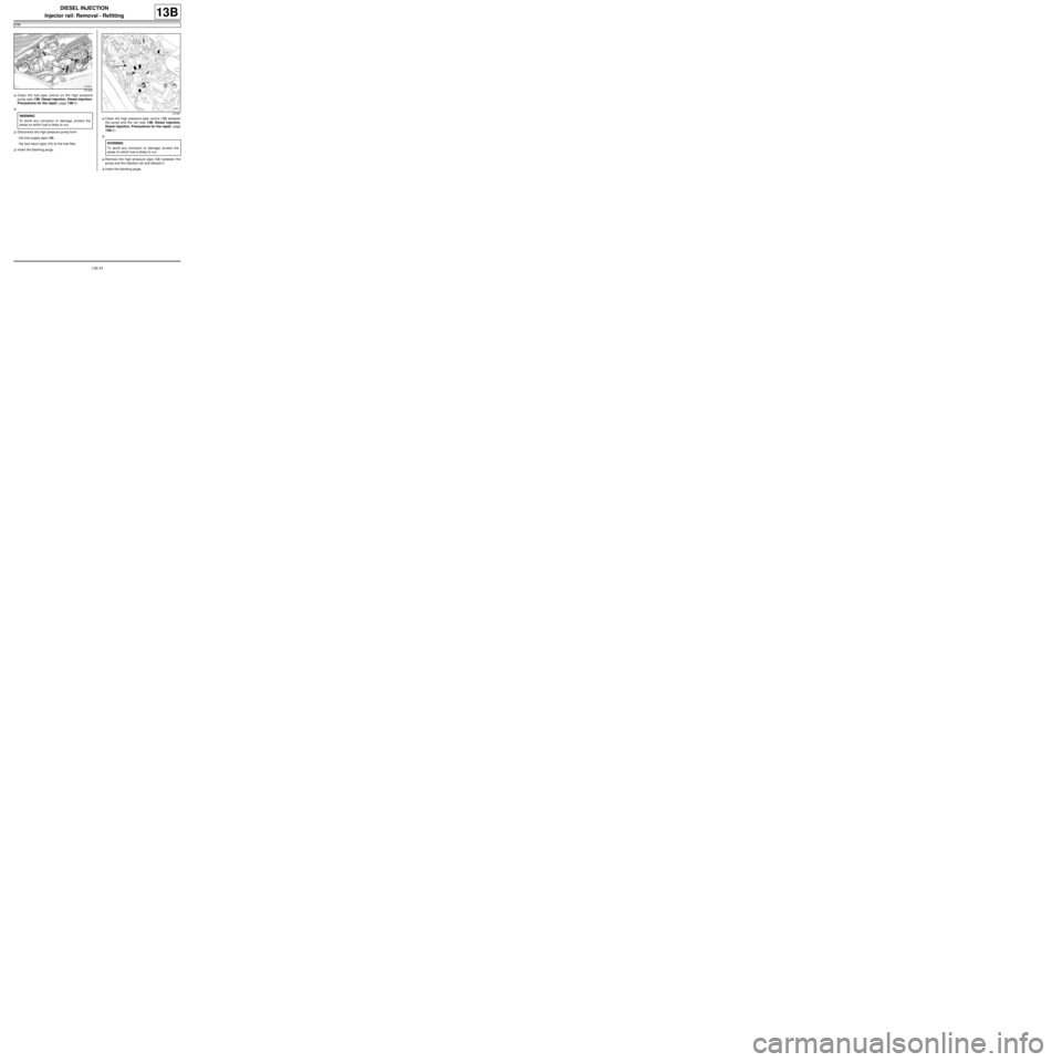
aClean the fuel pipe unions on the high pressure
pump (see 13B, Diesel injection, Diesel injection:
Precautions for the repair, page 13B-1) .
a
aDisconnect the high pressure pump from:
-the fuel supply pipe (10) ,
-the fuel return pipe (11) to the fuel filter.
aInsert the blanking plugs.aClean the high pressure pipe unions (12) between
the pump and the rail (see 13B, Diesel injection,
Diesel injection: Precautions for the repair, page
13B-1) .
a
aRemove the high pressure pipe (12) between the
pump and the injection rail and discard it.
aInsert the blanking plugs.
121423
WARNING
To avoid any corrosion or damage, protect the
areas on which fuel is likely to run.127901
WARNING
To avoid any corrosion or damage, protect the
areas on which fuel is likely to r un.
Page 407 of 652
13B-46
DIESEL INJECTION
Injector rail: Removal - Refitting
K9K
13B
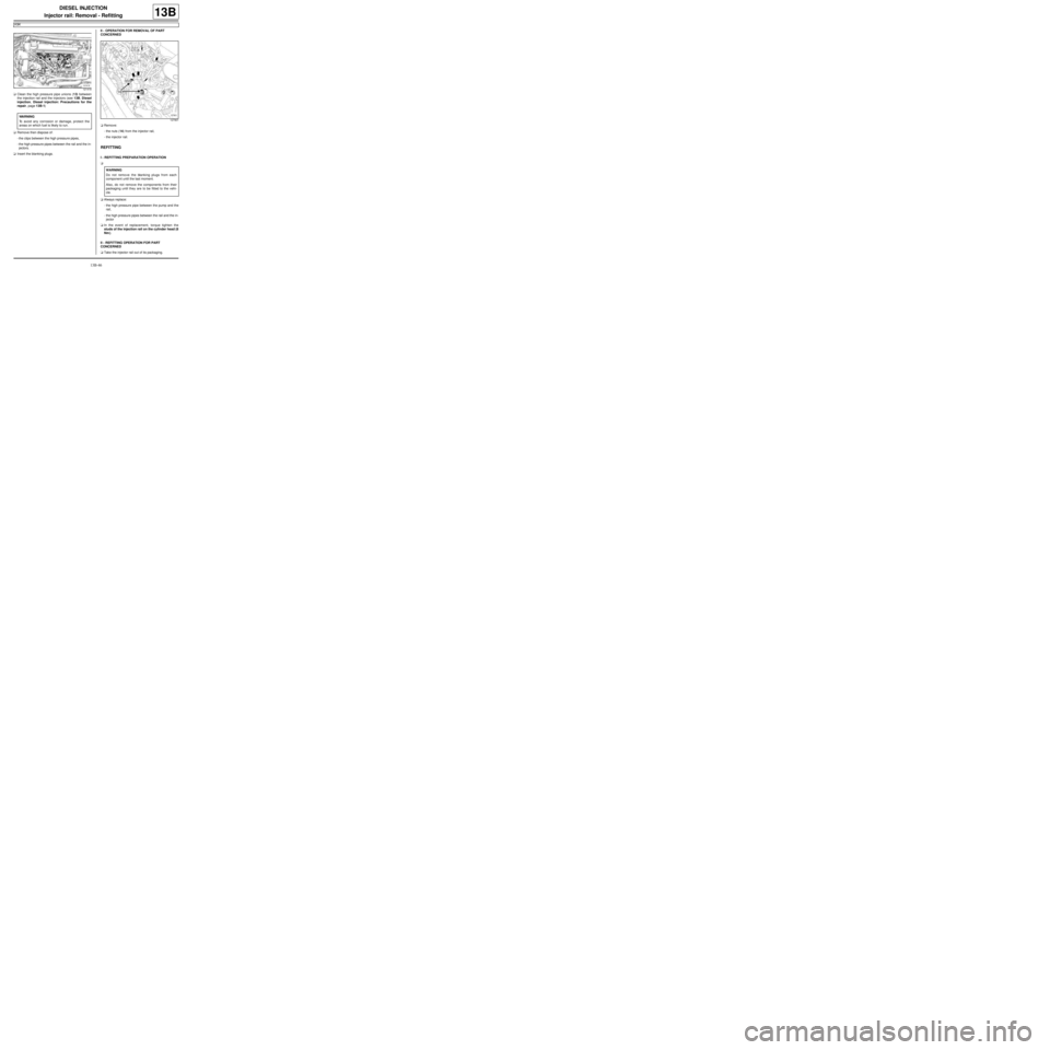
aClean the high pressure pipe unions (13) between
the injection rail and the injectors (see 13B, Diesel
injection, Diesel injection: Precautions for the
repair, page 13B-1)
aRemove then dispose of:
-the clips between the high pressure pipes,
-the high pressure pipes between the rail and the in-
jectors.
aInsert the blanking plugs.II - OPERATION FOR REMOVAL OF PART
CONCERNED
aRemove:
-the nuts (14) from the injector rail,
-the injector rail.
REFITTING
I - REFITTING PREPARATION OPERATION
a
aAlways replace:
-the high pressure pipe between the pump and the
rail,
-the high pressure pipes between the rail and the in-
jector
aIn the event of replacement, torque tighten the
studs of the injection rail on the cylinder head (8
Nm ).
II - REFITTING OPERATION FOR PART
CONCERNED
aTake the injector rail out of its packaging.
121418
WARNING
To avoid any corrosion or damage, protect the
areas on which fuel is likely to run.
127901
WARNING
Do not remove the blanking plugs from each
component until the last moment.
Also, do not remove the components from their
packaging until they are to be fitted to the vehi-
cle.
Page 408 of 652
13B-47
DIESEL INJECTION
Injector rail: Removal - Refitting
K9K
13B
aRemove the blanking plugs.
aFit the injector rail.
aFit the injector rail nuts without tightening them.
III - FINAL OPERATION.
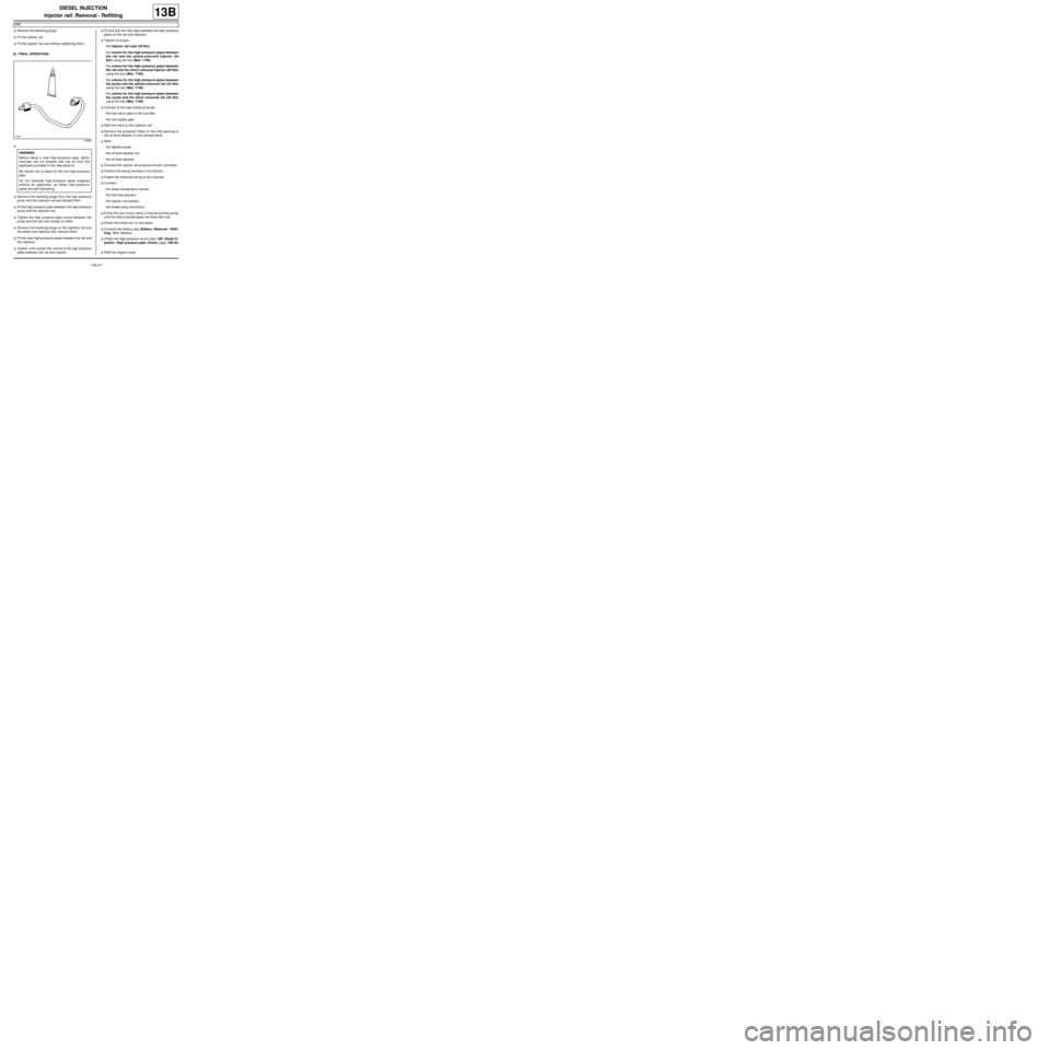
a
aRemove the blanking plugs from the high pressure
pump and the injection rail and discard them.
aFit the high pressure pipe between the high pressure
pump and the injection rail.
aTighten the high pressure pipe unions between the
pump and the rail until contact is made.
aRemove the blanking plugs on the injection rail and
the diesel fuel injectors then discard them.
aFit the new high-pressure pipes between the rail and
the injectors.
aTighten until contact the unions of the high pressure
pipes between the rail and injector.aFit and lock the new clips between the high pressure
pipes on the rail and injectors.
aTighten to torque:
-the injector rail nuts (28 Nm),
-the unions for the high pressure pipes between
the rail and the yellow-coloured injector (24
Nm) using the tool (Mot. 1746),
-the unions for the high pressure pipes between
the rail and the silver-coloured injector (28 Nm)
using the tool (Mot. 1746),
-the unions for the high pressure pipes between
the pump and the yellow-coloured rail (24 Nm)
using the tool (Mot. 1746),
-the unions for the high pressure pipes between
the pump and the silver-coloured rail (28 Nm)
using the tool (Mot. 1746),
aConnect to the high pressure pump:
-the fuel return pipe to the fuel filter,
-the fuel supply pipe.
aRefit the neck on the injection rail.
aRemove the protection fitted on the inlet opening of
the oil level dipstick on the cylinder block.
aRefit:
-the dipstick guide,
-the oil level dipstick nut,
-the oil level dipstick.
aConnect the injector rail pressure sensor connector.
aPosition the wiring harness in its channel.
aFasten the electrical wiring to the channel.
aConnect:
-the diesel temperature sensor,
-the fuel flow actuator,
-the injector connectors,
-the heater plug connectors.
aPrime the fuel circuit using a manual priming pump
until the disconnected pipes are filled with fuel.
aCheck that there are no fuel leaks.
aConnect the battery (see Battery: Removal - Refit-
ting) (80A, Battery).
aCheck the high pressure circuit (see 13B, Diesel in-
jection, High pressure pipe: Check, page 13B-34)
.
aRefit the engine cover.
20960
WARNING
Before fitting a new high-pressure pipe, lightly
lubricate the nut threads with the oil from the
applicator provided in the new parts kit.
Be careful not to allow oil into the high-pressure
pipe.
Do not lubricate high-pressure pipes supplied
without an applicator, as these high-pressure
pipes are self-lubricating.
Page 409 of 652
13B-48
DIESEL INJECTION
Rail pressure sensor: Removal - Refitting
K9K
13B
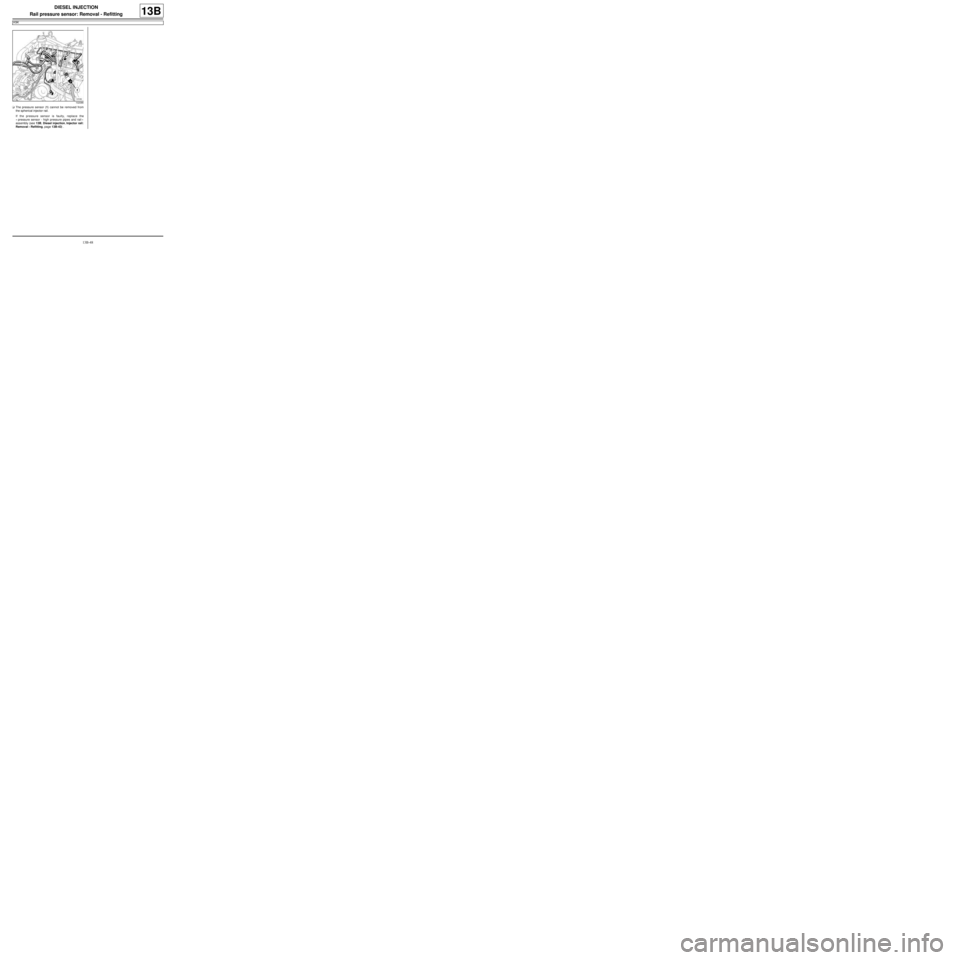
aThe pressure sensor (1) cannot be removed from
the spherical injector rail.
If the pressure sensor is faulty, replace the
« pressure sensor - high pressure pipes and rail »
assembly (see 13B, Diesel injection, Injector rail:
Removal - Refitting, page 13B-43) .
102086
Page 413 of 652
13B-52
DIESEL INJECTION
Injector leak flow: Check
K9K
13B
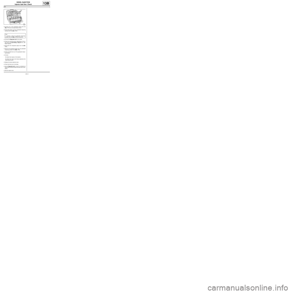
aConnect four of the transparent pipes (3) of the
(Mot. 1711) onto the diesel injector return.
aInsert these pipes in the four graduated measuring
cylinders (4) of the (Mot. 1711).
aConnect the Diagnostic tool to the vehicle.
aFollow the instructions given (depending on the en-
gine suffix) (see Fault finding - tests)(MR 413, 13B,
Diesel injection).
aDisconnect the transparent pipes from the (Mot.
1711).
aRemove the transparent pipes from the graduated
measuring cylinder of the (Mot. 1711).
aEmpty the diesel fuel out of the graduated measur-
ing cylinders.
aConnect:
-the diesel return pipes on the injectors,
-the diesel return pipe to the Venturi attached to the
high pressure pump.
aReplace the faulty injector(s) (see ) .
aCheck that there are no fuel leaks.
aUse the Diagnostic tool to check for an absence of
stored faults; deal with these and clear them as nec-
essary.
aRefit the engine cover.
107637
Note:
If necessary, attach the graduated measuring
cylinder rail of the (Mot. 1711) to the bonnet.
Page 441 of 652
16A-2
STARTING - CHARGING
Alternator: Removal - Refitting
D4F or D7F, and STANDARD HEATING
16A
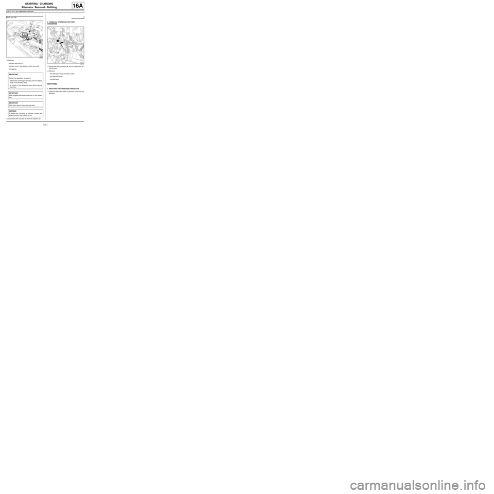
aRemove:
-the filler neck bolt (1) ,
-the filler neck in the direction of the arrow (2) ,
-the dipstick.
aDisconnect the fuel pipe (3) from the injector rail.II - REMOVAL OPERATION FOR PART
CONCERNED
aDisconnect the connector (4) from the alternator wir-
ing harness.
aRemove:
-the alternator wiring harness nut (5) ,
-the alternator bolts,
-the alternator.
REFITTING
I - REFITTING PREPARATIONS OPERATION
aClean the alternator pulley V-grooves to remove any
deposits. D4F, and 780
122392
IMPORTANT
During this operation, be sure to:
-refrain from smoking or bringing red hot objects
close to the working area,
-be careful of fuel splashes when disconnecting
the union.
IMPORTANT
Wear goggles with side protectors for this opera-
tion.
IMPORTANT
Wear latex gloves during the operation.
WARNING
To avoid any corrosion or damage, protect the
areas on which fuel is likely to run.
109727
Page 442 of 652
16A-3
STARTING - CHARGING
Alternator: Removal - Refitting
D4F or D7F, and STANDARD HEATING
16A
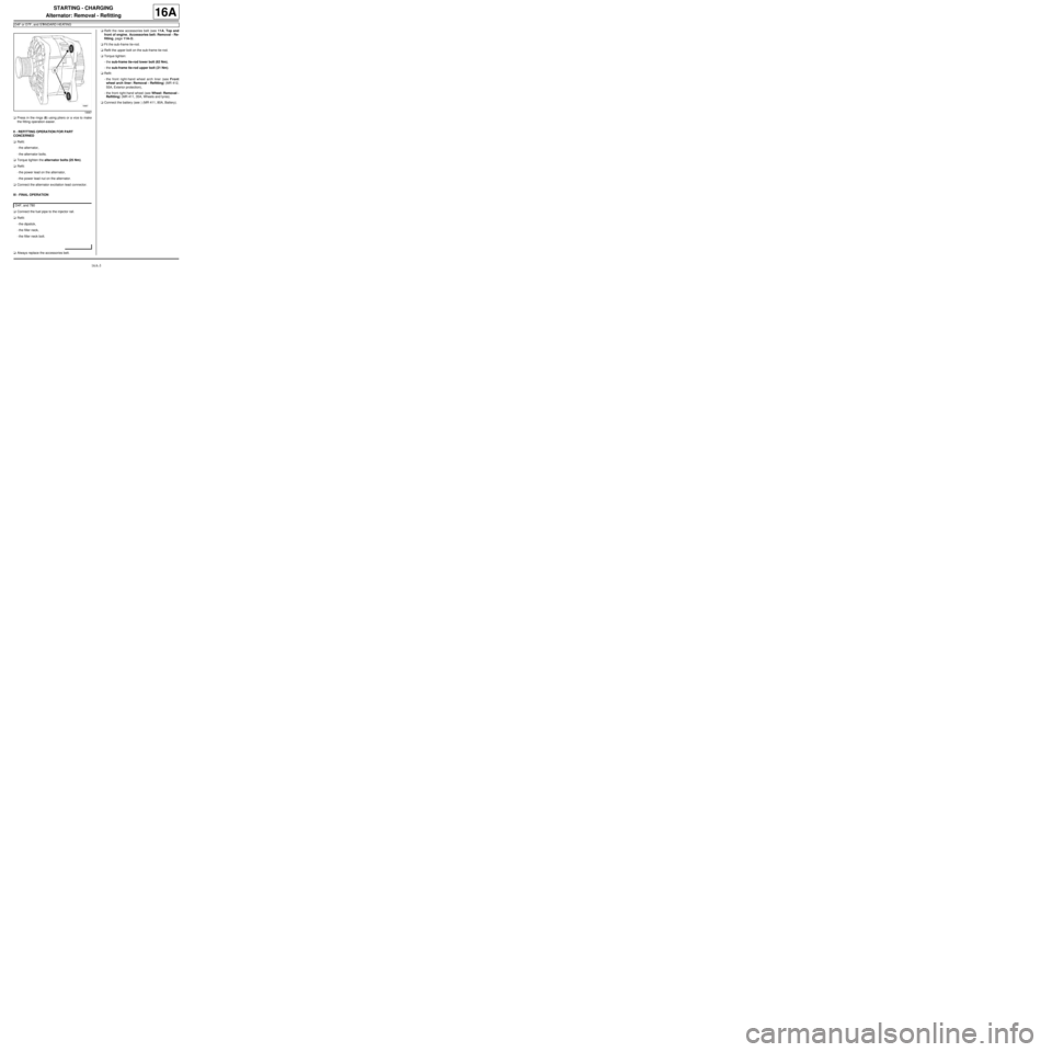
aPress in the rings (6) using pliers or a vice to make
the fitting operation easier.
II - REFITTING OPERATION FOR PART
CONCERNED
aRefit:
-the alternator,
-the alternator bolts.
aTorque tighten the alternator bolts (25 Nm).
aRefit:
-the power lead on the alternator,
-the power lead nut on the alternator.
aConnect the alternator excitation lead connector.
III - FINAL OPERATION
aConnect the fuel pipe to the injector rail.
aRefit:
-the dipstick,
-the filler neck,
-the filler neck bolt.
aAlways replace the accessories belt.aRefit the new accessories belt (see 11A, Top and
front of engine, Accessories belt: Removal - Re-
fitting, page 11A-3) .
aFit the sub-frame tie-rod.
aRefit the upper bolt on the sub-frame tie-rod.
aTorque tighten:
-the sub-frame tie-rod lower bolt (62 Nm),
-the sub-frame tie-rod upper bolt (21 Nm).
aRefit:
-the front right-hand wheel arch liner (see Front
wheel arch liner: Removal - Refitting) (MR 412,
55A, Exterior protection),
-the front right-hand wheel (see Wheel: Removal -
Refitting) (MR 411, 35A, Wheels and tyres).
aConnect the battery (see ) (MR 411, 80A, Battery).
18987
D4F, and 780
Page 484 of 652
17B-9
PETROL INJECTION
Petrol injection: List and location of components
K4M
17B
131776
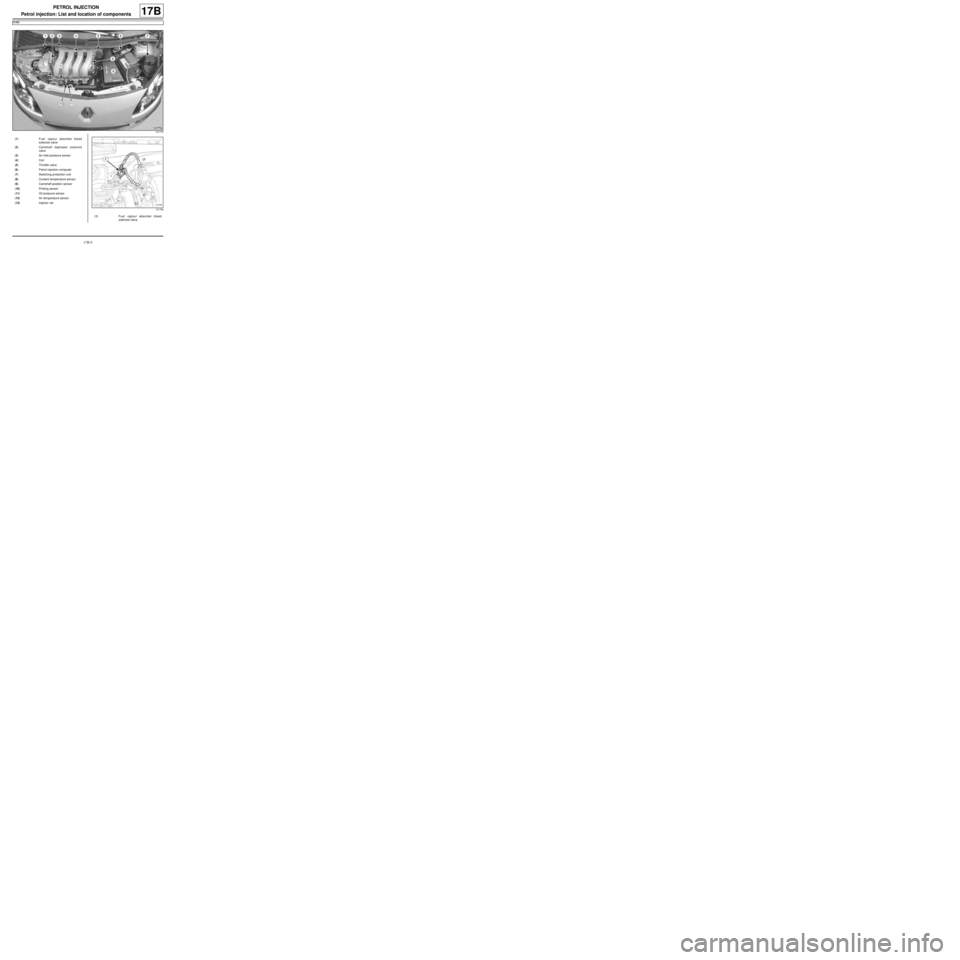
(1) Fuel vapour absorber bleed
solenoid valve
(2) Camshaft dephaser solenoid
valve
(3) Air inlet pressure sensor
(4) Coil
(5) Throttle valve
(6) Petrol injection computer
(7) Switching protection unit
(8) Coolant temper ature sensor
(9) Camshaft position sensor
(10) Pinking sensor
(11) Oil pressure sensor
(12) Air temperature sensor
(13) Injector rail
131766
(1) Fuel vapour absorber bleed
solenoid valve
Page 487 of 652

17B-12
PETROL INJECTION
Petrol injection: List and location of components
K4M
17B
132390
(13) Injector rail
132539
(14) upstream oxygen sensor
132378
(15) Downstream oxygen sensor
132445
(16) Crankshaft position sensor
Page 502 of 652
17B-27
PETROL INJECTION
Injector rail - Injectors: Removal - Refitting
D4F, and 772
17B
PARTS AND CONSUMABLES FOR THE
REPAIR WORK
aPièces à remplacer systématiquement :
-injector O-ring's,
-injector retaining clips.
REMOVAL
I - REMOVAL PREPARATION OPERATION
aDisconnect the battery (see Battery: Removal - Re-
fitting) ).
aRemove:
-the air filter box (see 12A, Fuel mixture, Air filter
unit: Removal - Refitting, page 12A-13) ,
-the intake distributor (see 12A, Fuel mixture, Inlet
distributor: Removal - Refitting, page 12A-29) .II - OPERATION FOR REMOVAL OF PART
CONCERNED
On the workbench
aDisconnect the injector wiring harness.
aRemove:
-the injector rail bolts (1) ,
-the injector rail,
-the injector wiring harness.
aRemove:
-the clips (2) from the injectors, IMPORTANT
During this operation, be sure to:
-refrain from smoking or bringing red hot objects
close to the working area,
-be careful of fuel splashes when disconnecting
the union.
IMPORTANT
Wear latex gloves during the operation.
107885
101492