RENAULT TWINGO 2009 2.G Engine And Peripherals Workshop Manual
TWINGO 2009 2.G
RENAULT
RENAULT
https://www.carmanualsonline.info/img/7/1710/w960_1710-0.png
RENAULT TWINGO 2009 2.G Engine And Peripherals Workshop Manual
Trending: oil change, diagram, handbrake, glove box, oil dipstick, change time, heater
Page 351 of 652
13A-8
FUEL SUPPLY
Fuel circuit: Operating diagram
D4F or D7F or K4M
13A
Operating diagram of the fuel supply circuit ( « pump - sender - fuel filter » assembly)
The fuel supply circuit does not have a return.
The fuel pressure does not vary with engine load.
The circuit comprises:
-a rail (1) without a return pipe union and without a
supply pressure regulator,
-a single pipe (2) coming from the tank,
-a « pump - sender - fuel filter » supply assembly fitted
with a pressure regulator (3) , fuel pump (4) and fuel
filter (5) (all located in the tank),
-a fuel vapour recirculation tank (6) .
109471
Page 352 of 652
13A-9
FUEL SUPPLY
Fuel pressure: Check
D4F or D7F
13A
CHECK
aI - PREPARATION OPERATION FOR CHECK
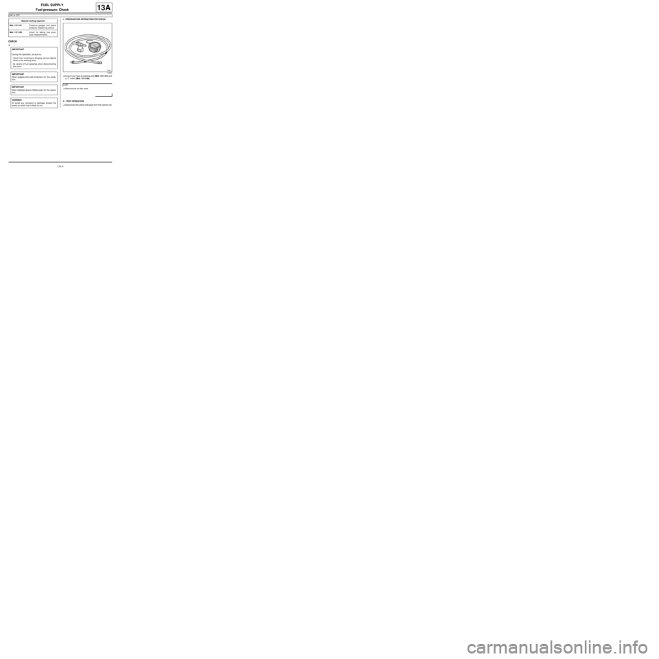
aEnsure you have a checking tool (Mot. 1311-01) and
a “T” union (Mot. 1311-08).
aRemove the oil filler neck.
II - TEST OPERATION
aDisconnect the petrol inlet pipe from the injector rail. Special tooling required
Mot. 1311-01Pressure gauges and petrol
pressure measur ing unions.
Mot. 1311-08Union for taking fuel pres-
sure measurements .
IMPORTANT
During this operation, be sure to:
-refrain from smoking or bringing red hot objects
close to the working area,
-be careful of fuel splashes when disconnecting
the union.
IMPORTANT
Wear goggles with side protectors for this opera-
tion.
IMPORTANT
Wear leaktight gloves (Nitrile type) for this opera-
tion.
WARNING
To avoid any corrosion or damage, protect the
areas on which fuel is likely to run.
116887
D4F
Page 353 of 652
13A-10
FUEL SUPPLY
Fuel pressure: Check
D4F or D7F
13A
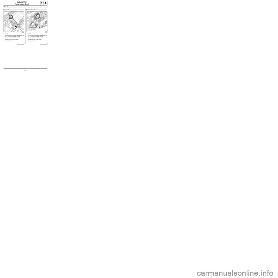
aConnect:
-the pipe fitted with a pressure checking gauge with
the “T” union of the tool (Mot. 1311-08),
-the “T” union to the rail,
-the petrol inlet duct to the “T” union.
aRefit the oil filler neck.aConnect:
-the pipe fitted with a pressure checking gauge with
the “T” union of the tool (Mot. 1311-08),
-the “T” union to the rail,
-the petrol inlet duct to the “T” union.
aRefit the oil filler neck. D4F, and 772
121821
D4F, and 780 or 782
121728
Page 354 of 652
13A-11
FUEL SUPPLY
Fuel pressure: Check
D4F or D7F
13A
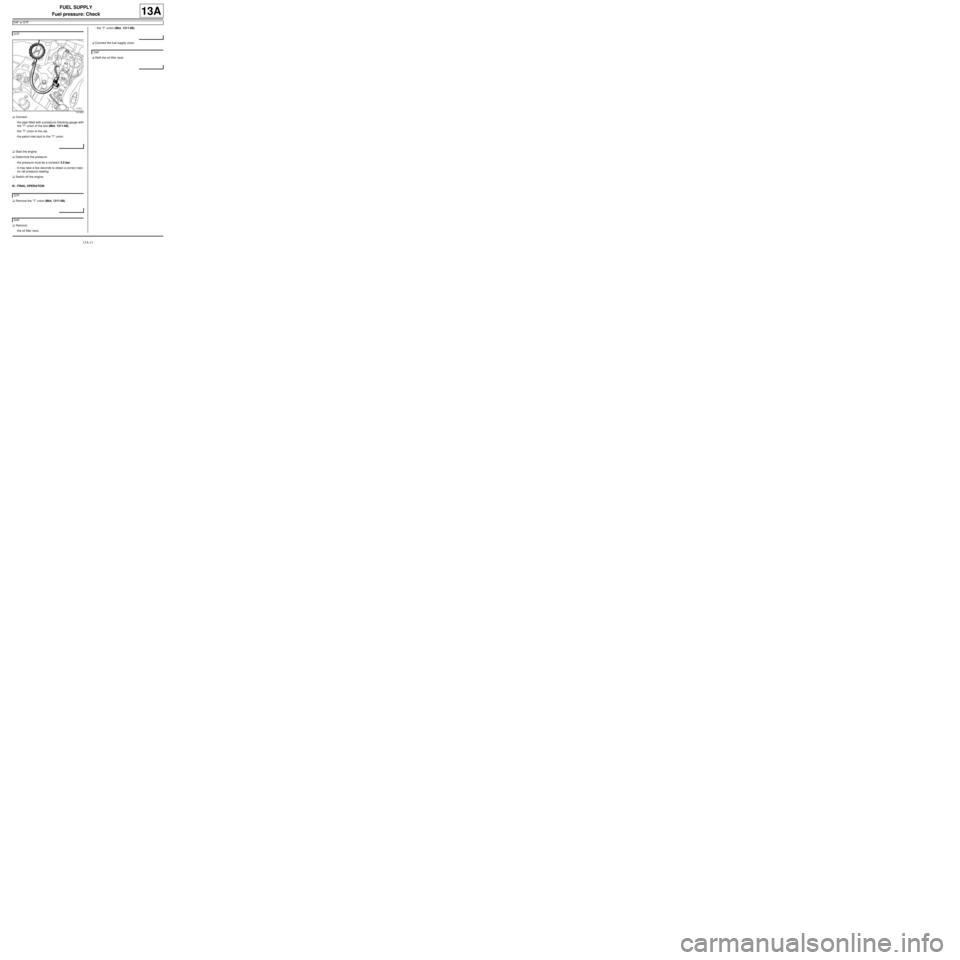
aConnect:
-the pipe fitted with a pressure checking gauge with
the “T” union of the tool (Mot. 1311-08),
-the “T” union to the rail,
-the petrol inlet duct to the “T” union.
aStart the engine.
aDetermine the pressure:
-the pressure must be a constant 3.5 bar,
-It may take a few seconds to obtain a correct injec-
tor rail pressure reading.
aSwitch off the engine.
III - FINAL OPERATION
aRemove the “T” union (Mot. 1311-08).
aRemove:
-the oil filler neck,-the “T” union (Mot. 1311-08).
aConnect the fuel supply union.
aRefit the oil filler neck. D7F
121822
D7F
D4F
D4F
Page 355 of 652
13A-12
FUEL SUPPLY
Fuel pressure: Check
K4M
13A
CHECK
aI - PREPARATION OPERATION FOR CHECK
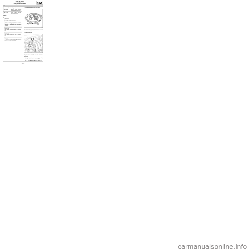
aEnsure you have a checking tool (Mot. 1311-01) and
a “T” union (Mot. 1311-08).
II - TEST OPERATION
aDisconnect the fuel supply union from the injector
rail.
aConnect:
-the pipe fitted with a test pressure gauge (Mot.
1311-01) with the "T" union (Mot. 1311-08),
-the "T" union (Mot. 1311-08) on the injector rail, Special tooling required
Mot. 1311-01Pressure gauges and petrol
pressure measur ing unions.
Mot. 1311-08Union for taking fuel pres-
sure measurements .
IMPORTANT
During this operation, be sure to:
-refrain from smoking or bringing red hot objects
close to the working area,
-be careful of fuel splashes when disconnecting
the union.
IMPORTANT
Wear goggles with side protectors for this opera-
tion.
IMPORTANT
Wear leaktight gloves (Nitrile type) for this opera-
tion.
WARNING
To avoid any corrosion or damage, protect the
areas on which fuel is likely to run.
116887
132333
Page 356 of 652
13A-13
FUEL SUPPLY
Fuel pressure: Check
K4M
13A
-the injector rail fuel supply union to the "T" union
(Mot. 1311-08).
aStart the engine.
aRecord the pressure; this should be constant at 3.5
bar.
aSwitch off the engine.
III - FINAL OPERATION
aDisconnect the "T" union (Mot. 1311-08) from the in-
jector rail.
aConnect the fuel supply pipe union on the injector
rail.Note:
It may take a few seconds to obtain a correct
injector rail pressure reading.
Page 357 of 652
13A-14
FUEL SUPPLY
Fuel flow: Check
D4F or D7F
13A
CHECK
a
I - PREPARATION OPERATION FOR CHECK
aRemove the oil filler neck.
aDisconnect the fuel supply union.aFit a “T” union to the fuel supply union (Mot. 1311-
08).
aFit a pipe which is long enough to drain the pump
into a container to the “T” outlet union. Special tooling required
Mot. 1311-08Union for taking fuel pres-
sure measurements .
Equipment required
graduated measuring cylinder
IMPORTANT
During this operation, be sure to:
-refrain from smoking or bringing red hot objects
close to the working area,
-be careful of fuel splashes when disconnecting
the union.
IMPORTANT
Wear goggles with side protectors for this opera-
tion.
IMPORTANT
Wear leaktight gloves (Nitrile type) for this opera-
tion.
WARNING
To avoid any corrosion or damage, protect the
areas on which fuel is likely to run.
D4F
D4F, and 772
121778
Page 358 of 652
13A-15
FUEL SUPPLY
Fuel flow: Check
D4F or D7F
13A
aFit a “T” union to the fuel supply union (Mot. 1311-
08).
aFit a pipe which is long enough to drain the pump
into a container to the “T” outlet union.aFit a “T” union to the fuel supply union (Mot. 1311-
08).
aFit a pipe which is long enough to drain the pump
into a container to the “T” outlet union.
II - CHECK
aImmerse the pipe into a graduated measuring cyl-
inder (2000 ml).
aRemove the cover from the engine compartment
connection unit. D4F, and 780 or 782
121729
D7F
121779
Page 359 of 652
13A-16
FUEL SUPPLY
Fuel flow: Check
D4F or D7F
13A
aRemove the relay (1) .
aShunt the relay to supply the electric fuel pump.
III - FINAL OPERATION
aRefit:
-the fuel pump relay,
-the cover of the engine compartment connection
unit.
aRemove the “T” union (Mot. 1311-08).
aConnect the fuel supply union.
aRefit the oil filler neck.
119373
Note:
The flow reading should be 80 to 120 l/h.
D4F
Page 360 of 652
13A-17
FUEL SUPPLY
Fuel flow: Check
K4M
13A
I - PREPARATION OPERATION FOR CHECK
aEnsure you have a checking tool (Mot. 1311-01) and
a “T” union (Mot. 1311-08).
aAssemble the long hose of the test tool (Mot. 1311-
01) and the "T" union (Mot. 1311-08).
aDisconnect the fuel supply union on the injector rail.aConnect:
-the "T" union (Mot. 1311-08) on the injector rail,
-the fuel supply union to the "T" union (Mot. 1311-
08).
II - FUEL FLOW CHECK
aImmerse the hose in a 2000 ml graduated measur-
ing cylinder.
aRemove the cover from the engine compartment
connection unit. Special tooling required
Mot. 1311-01Pressure gauges and petrol
pressure measur ing unions.
Mot. 1311-08Union for taking fuel pres-
sure measurements .
Equipment required
graduated measuring cylinder
IMPORTANT
During this oper ation, be sure to:
-refrain from smoking or bringing red hot objects
close to the working area,
-be careful of fuel splashes when disconnecting the
union.
IMPORTANT
Wear leaktight gloves (Nitrile type) for this opera-
tion.
IMPORTANT
Wear goggles with side protectors for this opera-
tion.
WARNING
To avoid any corrosion or damage, protect the
areas on which fuel is likely to run.
132334
Trending: clock setting, wheel size, heating, towing, air conditioning, glove box, technical specifications

