lock RENAULT TWINGO 2009 2.G Engine Diesel Injection Workshop Manual
[x] Cancel search | Manufacturer: RENAULT, Model Year: 2009, Model line: TWINGO, Model: RENAULT TWINGO 2009 2.GPages: 269
Page 5 of 269
13B-5V6 MR-413-X44-13B000$010.mif
DIESEL INJECTION
Fault finding – Introduction13B
DCM 1.2 Injection
Program No.: 4D
Vdiag No.: 48, 4C, 50,
54, 58, 5C
4. FAULT FINDING PROCEDURE (continued)
4.1 Wiring check
Fault finding problems
Disconnecting the connectors and/or handling the wiring harness may temporarily remove, the cause of a fault.
Visual inspection
Look for damage under the bonnet and in the passenger compartment.
Carefully check the protectors, insulation, and routing of the wiring, as well as the mountings.
Physical inspection
While manipulating the wiring, use either the diagnostic tool to detect a change in status from "stored" to "present",
or use the multimeter to view the status changes.
Make sure that the connectors are properly locked.
Apply light pressure to the connectors.
Twist the wiring harness.
Checking earth insulation
This check is carried out by measuring the voltage (multimeter in voltmeter mode) between the suspect connection
and the 12 V or 5 V. The correct measured value is 0 V.
Checking insulation against + 12 V or + 5 V
This check is carried out by measuring the voltage (multimeter in voltmeter mode) between the suspect connection
and the earth. In the first instance, the earth may be taken on the chassis. The correct measured value should
be 0 V.
Continuity check
A continuity check is carried out by measuring the resistance (multimeter in ohmmeter mode), with the connectors
disconnected at both ends. The expected result is: 1 Ω ± 1 Ω for each connection. The line must be fully checked,
and the intermediate connections are only included in the method if this saves time during the fault finding
procedure. The continuity check on the multiplex lines must be carried out on both wires. The measured value
should be 1 Ω ± 1 Ω
Checking the supply
This check may be carried out using a test light (21 W or 5 W depending on the maximum authorised load).
Page 6 of 269
13B-6V6 MR-413-X44-13B000$010.mif
DIESEL INJECTION
Fault finding – Introduction13B
DCM 1.2 Injection
Program No.: 4D
Vdiag No.: 48, 4C, 50,
54, 58, 5C
4.2 Connector check
1. Visual inspection of the connection:
–Check that the connector is connected correctly and that the male and female parts of the connection are
correctly coupled.
2. Visual inspection of the area around the connection:
–Check the condition of the mounting (pin, strap, adhesive tape, etc.) if the connectors are attached to
the vehicle.
–Check that there is no damage to the wiring trim (sheath, foam, adhesive tape, etc.) near the wiring.
–Check that there is no damage to the electrical wires at the connector outputs, in particular on the insulating
material (wear, cuts, burns, etc.).
Disconnect the connector to continue the checks.
3. Visual inspection of the plastic casing:
–Check that there is no mechanical damage (casing crushed, split, broken, etc.), in particular to the fragile
components (lever, lock, sockets, etc.).
–Check that there is no heat damage (casing melted, darker, deformed, etc.).
–Check that there are no stains (grease, mud, liquid, etc.).
4. Visual inspection of the metal contacts:
(The female contact is called CLIP. The male contact is called TAB.)
–Check that there are no bent contacts (the contact is not inserted correctly and can come out of the back of
the connector). The spring contact of the connector when the wire is pulled slightly.
–Check that there is no damage (folded tabs, clips open too wide, blackened or melted contact, etc.).
–Check that there is no oxidation on the metal contacts.
5. Visual inspection of the sealing:
(Only for watertight connectors)
–Check for the seal on the connection (between the 2 parts of the connection).
–Check the seal at the back of the connectors:
–For unit seals (1 for each wire), check that the unit seals are present on each electrical wire and that they are
correctly positioned in the opening (level with the housing). Check that plugs are present on openings which
are not used.
–For a grommet seal (one seal which covers the entire internal surface of the connector), check that the seal is
present.
–For gel seals, check for gel in all of the sockets without removing the excess or any protruding sections (it does
not matter if there is gel on the contacts).
–For hotmelt sealing (heat-shrink sheath with glue), check that the sheath has contracted correctly on the rear
of the connectors and the electrical wires, and that the hardened glue comes out of the side of the wire.
–Check that there is no damage to any of the seals (cuts, burns, significant deformation, etc.).
If a fault is detected, consult Technical Note 6015A, Repairing electrical wiring. Note:
Carry out each requested check visually. Do not remove a connector if it is not required.
Note:
Repeated connections and disconnections alter the functionality of the connectors and increase the risk of poor
electrical contact. Limit the number of connections/disconnections as much as possible.
Note:
The check is carried out on the 2 parts of the connection. There may be 2 types of connections:
–Connector/Connector.
–Connector/Device.
Page 11 of 269
13B-11V6 MR-413-X44-13B000$030.mif
DIESEL INJECTION
Fault finding – List and location of components13B
DCM 1.2 Injection
Program No.: 4D
Vdiag No.: 48, 4C, 50,
54, 58, 5C
Refrigerant pressure sensor:
This sensor is located on the coolant circuit.
Engine coolant temperature sensor:
This sensor is located on the cylinder head near the engine water chamber.
Accelerometer:
This sensor is located on the cylinder block.
Passenger compartment heating resistor relay:
These relays are located in the engine compartment relay unit.
Air conditioning compressor relays:
These relays are located in the engine compartment relay unit.
Fan unit relay:
These relays are located in the engine compartment relay unit.
Page 26 of 269
13B-26V6 MR-413-X44-13B000$070.mif
13B
DCM 1.2 Injection
Program No.: 4D
Vdiag No.: 48, 4C, 50,
54, 58, 5C
CONFIGURATION READING
SETTINGS
VP001:Cylinder 1 injector code.
VP002:Cylinder 2 injector code.
VP003:Cylinder 3 injector code.
VP004:Cylinder 4 injector code.
These commands enable you to manually write the calibration code marked on the injector. Use these commands
after replacing the injector or replacing or (re)programming the computer, when command SC001 Enter saved data
does not work.
VP010:Enter VIN.
This command permits manual entry of the vehicle's VIN into the computer.
Use this command each time the computer is replaced or (re)programmed.
VP013:Lock injector control.
This command disables electrical actuation of the injectors, for carrying out the compression test.
SPECIAL COMMANDS
SC001:Enter saved data.
Use this command after replacing or (re)programming the computer (if the data were saved using
command SC003 Save computer data).
SC002:Enter injector codes.
This command enables you to manually write the calibration code marked on the injectors. Run this
command after replacing the injectors.
SC003:Save computer data.
This command saves the computer's operating data, C2I (individual injector correction) parameters
and engine adaptives. Run this command before replacing or (re)programming.
SC040:Speed limiter.
This command is used to change the vehicle restriction speed. Run this command after replacing
or (re)programming.
SC041:Modification of CV* idle speed.
This command is used to change the idle speed. Run this command after replacing or (re)programming.
* CV: Commercial vehicleIndex Title Display comment
LC120 Cruise controlWith or Without
LC121 Speed limiterWith or Without
LC172 FlowmeterWith or Without
DIESEL INJECTION
Fault finding – Configuration and programming
Page 32 of 269
13B-32
AFTER REPAIRDeal with any faults displayed by the diagnostic tool.
Clear the computer fault memory.
Carry out a road test followed by another check with the diagnostic tool.
V6 MR-413-X44-13B000$090.mif
DIESEL INJECTION
Fault finding – Interpretation of faults13B
DCM 1.2 Injection
Program No.: 4D
Vdiag No.: 48, 4C, 50,
54, 58, 5C
DF003
PRESENT
OR STOREDATMOSPHERIC PRESSURE SENSOR CIRCUITCO.0: Open circuit or short circuit to earth
CC.1: Short circuit to +12 volts
NOTESSpecial note:
The atmospheric pressure sensor is incorporated in the computer.
See the Technical Note Wiring Diagrams for the vehicle.
Look for any wiring damage and check the condition and connection of the injection computer connectors,
component code 120.
Move the wiring between the injection computer, component code 120 and the battery, component code 107
to see if a change of status occurs (Present Stored).
Look for any wiring damage and check the connection and condition of the battery, component code 107
and its connections.
If the connector(s) are faulty and if there is a repair procedure (see Technical Note 6015A, Repairing electrical
wiring, Wiring: Precautions for repair) repair the connector(s), otherwise replace the wiring.
Measure the battery voltage when the ignition is switched on.
If the battery voltage is less than 11 V, recharge the battery.
Check the connection and condition of the battery terminals and posts, component code 107.
Check the connection and condition of connector A (black 32-track) of the injection computer, component
code 120.
Check the connection and condition of the connector of the injection locking relay or of the UPC, according to
the vehicle.
If the connector(s) are faulty and if there is a repair procedure (see Technical Note 6015A, Repairing electrical
wiring, Wiring: Precautions for repair) repair the connector(s), otherwise replace the wiring.
DCM1.2_V48_DF003/DCM1.2_V4C_DF003/DCM1.2_V50_DF003/DCM1.2_V54_DF003/DCM1.2_V58_DF003/DCM1.2_V5C_DF003
Page 45 of 269
13B-45
AFTER REPAIRDeal with any faults displayed by the diagnostic tool.
Clear the computer fault memory.
Carry out a road test followed by another check with the diagnostic tool.
V6 MR-413-X44-13B000$090.mif
DIESEL INJECTION
Fault finding – Interpretation of faults13B
DCM 1.2 Injection
Program No.: 4D
Vdiag No.: 48, 4C, 50,
54, 58, 5C
* VSU: Vehicle Speed Unit
DF014
PRESENT
OR STOREDVEHICLE SPEED SIGNAL CIRCUIT
NOTESSpecial note:
None.
On this type of vehicle, the ABS or the VSU* (if the vehicle is not fitted with ABS) transmits the vehicle speed
information via the multiplex network.
Run the multiplex network test (see 88B, Multiplexing) to be able to work on the CAN network (Fault on CAN H
and CAN L lines between the injection and the ABS). Also check that there are no faults in the ABS computer
(see 38C, Anti-lock braking system) or in the system delivering the vehicle speed (VSU, see 38G, Vehicle speed
computer).
DCM1.2_V48_DF014/DCM1.2_V4C_DF014/DCM1.2_V50_DF014/DCM1.2_V54_DF014/DCM1.2_V58_DF014/DCM1.2_V5C_DF014
Page 46 of 269
13B-46
AFTER REPAIRDeal with any faults displayed by the diagnostic tool.
Clear the computer fault memory.
Carry out a road test followed by another check with the diagnostic tool.
V6 MR-413-X44-13B000$090.mif
DIESEL INJECTION
Fault finding – Interpretation of faults13B
DCM 1.2 Injection
Program No.: 4D
Vdiag No.: 48, 4C, 50,
54, 58, 5C
DF015
PRESENT
OR STOREDMAIN RELAY CONTROL CIRCUIT1.DEF: Permanent low level
2.DEF: Permanent high signal
NOTESConditions for applying fault finding procedures to stored faults:
Apply the fault finding procedure below if the fault is present or stored.
See the Technical Note Wiring Diagrams for the vehicle.
For Clio III, Modus, Mégane II, Scénic II, and Kangoo 2:
Check the connection and condition of the UPC connectors; component code 1337.
If the connector(s) is faulty and if there is a repair procedure (see Technical Note 6015A, Repairing electrical
wiring, Wiring: Precautions for repair), repair the connector, otherwise replace the wiring.
For New Twingo:
Check the connection and condition of the injection locking relay connector, component code 238.
If the connector is faulty and if there is a repair procedure (see Technical Note 6015A, Repairing electrical
wiring, Wiring: Precautions for repair), repair the connector, otherwise replace the wiring.
Check the connection and condition of connector C (grey 32-track) of the injection computer, component
code 120.
If the connector is faulty and if there is a repair procedure (see Technical Note 6015A, Repairing electrical
wiring, Wiring: Precautions for repair), repair the connector, otherwise replace the wiring.
Check the insulation and continuity of the following connections:
–3AA between components 1337 and 120,
–3FB2 between components 1337 and 120,
–3FB1 between components 1337 and 120.
K9K 740 engines only:
–3FB between components 238 and 120,
–3AA between components 238 and 120.
If the connection or connections are faulty and there is a repair procedure (see Technical Note 6015A, Electrical
wiring repair, Wiring: Precautions for repair), repair the wiring, otherwise replace the wiring.
If the fault is still present, run a test of the Engine compartment connection unit (see 87G, Engine compartment
connection unit) or replace the main relay, component code 238.
If the fault is still present, contact the Techline.
DCM1.2_V48_DF015/DCM1.2_V4C_DF015/DCM1.2_V50_DF015/DCM1.2_V54_DF015/DCM1.2_V58_DF015/DCM1.2_V5C_DF015
Page 55 of 269
13B-55
AFTER REPAIRDeal with any faults displayed by the diagnostic tool.
Clear the computer fault memory.
Carry out a road test followed by another check with the diagnostic tool.
V6 MR-413-X44-13B000$090.mif
DIESEL INJECTION
Fault finding – Interpretation of faults13B
DCM 1.2 Injection
Program No.: 4D
Vdiag No.: 48, 4C, 50,
54, 58, 5C
DF026
PRESENT
OR STOREDCYLINDER 1 INJECTOR CONTROL CIRCUITC0: Open circuit
CC: Short circuit
1.DEF: At minimum stop
2.DEF: At maximum stop
NOTESConditions for applying fault finding procedures to stored faults:
The fault is present with the engine idling.
Special notes:
When fault DF026 occurs, the idle speed is locked at 1000 rpm, there is engine noise,
the engine speed is unstable, the engine performance is reduced to 75%, the level 1
warning light illuminates, and the message Check injector is displayed until the next
time the ignition is switched off.
See the Technical Note Wiring Diagrams for the vehicle.
C0 - CC
NOTESNone.
Switch off the ignition and wait 15 seconds.
Check the connection and condition of the cylinder 1 injector connector, component code 193.
Check the connection and condition of connector B (brown 48-track) of the injection computer, component
code 120.
If the connector(s) is faulty and if there is a repair procedure (see Technical Note 6015A, Repairing electrical
wiring, Wiring: Precautions for repair), repair the connector, otherwise replace the wiring.
Run command AC005 Cylinder 1 injector.
If injector 1 cannot be heard operating five times in a cycle, connect the wire of the cylinder 2 injector to
the cylinder 1 injector and run command AC006 Cylinder 2 injector.
Does this injector actuation cycle work?
Note:
If the wires cannot be swapped, continue the procedure by replying YES to the previous question.
DCM1.2_V48_DF026/DCM1.2_V4C_DF026/DCM1.2_V50_DF026/DCM1.2_V54_DF026/DCM1.2_V58_DF026/DCM1.2_V5C_DF026
Page 58 of 269
13B-58
AFTER REPAIRDeal with any faults displayed by the diagnostic tool.
Clear the computer fault memory.
Carry out a road test followed by another check with the diagnostic tool.
V6 MR-413-X44-13B000$100.mif
13B
DCM 1.2 Injection
Program No.: 4D
Vdiag No.: 48, 4C, 50,
54, 58, 5C
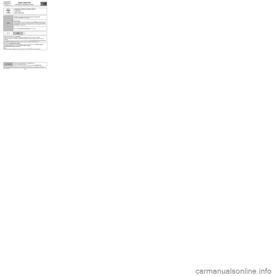
DF027
PRESENT
OR
STOREDINJECTOR CYLINDER 2 CONTROL CIRCUITC0: Open circuit
CC: Short circuit
1.DEF: At minimum stop
2.DEF: At maximum stop
NOTESConditions for applying fault finding procedures to stored faults:
The fault is present with the engine idling.
Special notes:
When fault DF027 occurs, the idle speed is locked at 1000 rpm, there is engine noise,
the engine speed is unstable, the engine performance is reduced to 75%, the level 1
warning light illuminates, and the message Check injector is displayed until the next
time the ignition is switched off.
See the Technical Note Wiring Diagrams for the vehicle.
C0 - CC
NOTESNone.
Switch off the ignition and wait 15 seconds.
Check the connection and condition of the cylinder 2 injector connector, component code 194.
Check the connection and condition of connector B (brown 48-track) of the injection computer, component
code 120.
If the connector(s) is faulty and if there is a repair procedure (see Technical Note 6015A, Repairing electrical
wiring, Wiring: Precautions for repair), repair the connector, otherwise replace the wiring.
Run command AC006 Cylinder 2 injector.
If injector 2 cannot be heard operating five times in a cycle, connect the wire of the cylinder 3 injector to
the cylinder 2 injector and run command AC007 Cylinder 3 injector.
Does this injector actuation cycle work?
Note:
If the wires cannot be swapped, continue the procedure by replying YES to the previous question.
DCM1.2_V48_DF027/DCM1.2_V4C_DF027/DCM1.2_V50_DF027/DCM1.2_V54_DF027/DCM1.2_V58_DF027/DCM1.2_V5C_DF027
DIESEL INJECTION
Fault finding – Interpretation of faults
Page 61 of 269
13B-61
AFTER REPAIRDeal with any faults displayed by the diagnostic tool.
Clear the computer fault memory.
Carry out a road test followed by another check with the diagnostic tool.
V6 MR-413-X44-13B000$100.mif
DIESEL INJECTION
Fault finding – Interpretation of faults13B
DCM 1.2 Injection
Program No.: 4D
Vdiag No.: 48, 4C, 50,
54, 58, 5C
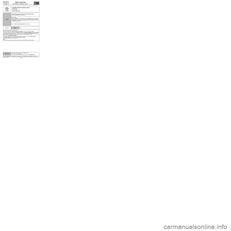
DF028
PRESENT
OR
STOREDCYLINDER 3 INJECTOR CONTROL CIRCUITC0: Open circuit
CC: Short circuit
1.DEF: At minimum stop
2.DEF: At maximum stop
NOTESConditions for applying fault finding procedures to stored faults:
The fault is present with the engine idling.
Special notes:
When fault DF028 occurs, the idle speed is locked at 1000 rpm, there is engine noise,
the engine speed is unstable, the engine performance is reduced to 75%, the level 1
warning light illuminates, and the message Check injector is displayed until the next
time the ignition is switched off.
See the Technical Note Wiring Diagrams for the vehicle.
C0 - CC
NOTESNone.
Switch off the ignition and wait 15 seconds.
Check the connection and condition of the cylinder 3 injector connector, component code 1954.
Check the connection and condition of connector B (48-track) of the injection computer, component code 120.
If the connector(s) is faulty and if there is a repair procedure (see Technical Note 6015A, Repairing electrical
wiring, Wiring: Precautions for repair), repair the connector, otherwise replace the wiring.
Run command AC007 Cylinder 3 injector.
If injector 3 cannot be heard operating five times in a cycle, connect the wire of the cylinder 4 injector to
the cylinder 3 injector and run command AC008 Cylinder 4 injector.
Does this injector actuation cycle work?
Note:
If the wires cannot be swapped, continue the procedure by replying YES to the previous question.
DCM1.2_V48_DF028/DCM1.2_V4C_DF028/DCM1.2_V50_DF028/DCM1.2_V54_DF028/DCM1.2_V58_DF028/DCM1.2_V5C_DF028