lock RENAULT TWINGO 2009 2.G Engine Diesel Injection Owner's Guide
[x] Cancel search | Manufacturer: RENAULT, Model Year: 2009, Model line: TWINGO, Model: RENAULT TWINGO 2009 2.GPages: 269
Page 227 of 269
13B-227V6 MR-413-X44-13B000$190.mif
DIESEL INJECTION
Fault finding – Tests13B
DCM 1.2 Injection
Program No.: 4D
Vdiag No.: 48, 4C, 50,
54, 58, 5C
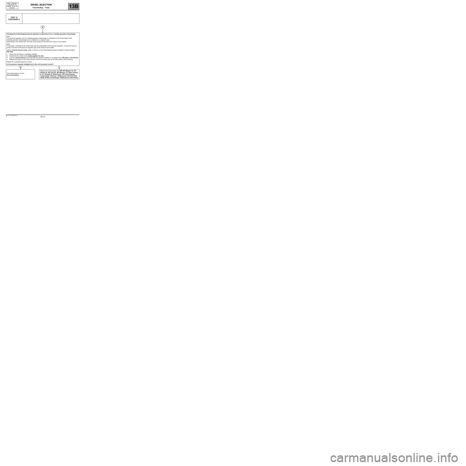
TEST 12
CONTINUED 2
Checking the turbocharging pressure regulator to determine if it is a variable geometry turbocharger
Note:
The pressure regulator rod of a variable geometry turbocharger is orthogonal to the turbocharger shaft.
Variable geometry turbochargers are controlled by a solenoid valve.
Depending on the vehicle type, the best visual access will be either from above or from below.
Note:
If necessary, according to the vehicle type and the accessibility of the pressure regulator, connect the vacuum
pump to the end of the pressure regulator pipe at the solenoid valve outlet.
Using a manual vacuum pump, apply a vacuum on the turbocharging pressure regulator of approximately
650 mbar.
1. Check that the fitting is completely leaktight.
2. Check that the control rod is resting against its stop.
3. Lock the vacuum device and check that the pressure variation is not greater than 100 mbar in 10 seconds.
4. Release the pressure and check that the control rod comes back to its initial position without jerking.
Repeat the complete sequence 3 times.
Is the pressure regulator leaktight and is the rod movement correct?
The turbocharger is correct.
End of procedure.Replace the turbocharger (see MR 364 (Mégane II), 370
(Scénic II), 392 (Clio III), 385 (Modus), 411 (New Twingo)
or 417 (Kangoo II), Mechanical, 12B turbocharging,
Turbocharger: Removal - Refitting and Technical Note
3938A, Broken turbocharger: Replacement instructions).
B
YESNO
Page 228 of 269
13B-228V6 MR-413-X44-13B000$190.mif
DIESEL INJECTION
Fault finding – Tests13B
DCM 1.2 Injection
Program No.: 4D
Vdiag No.: 48, 4C, 50,
54, 58, 5C
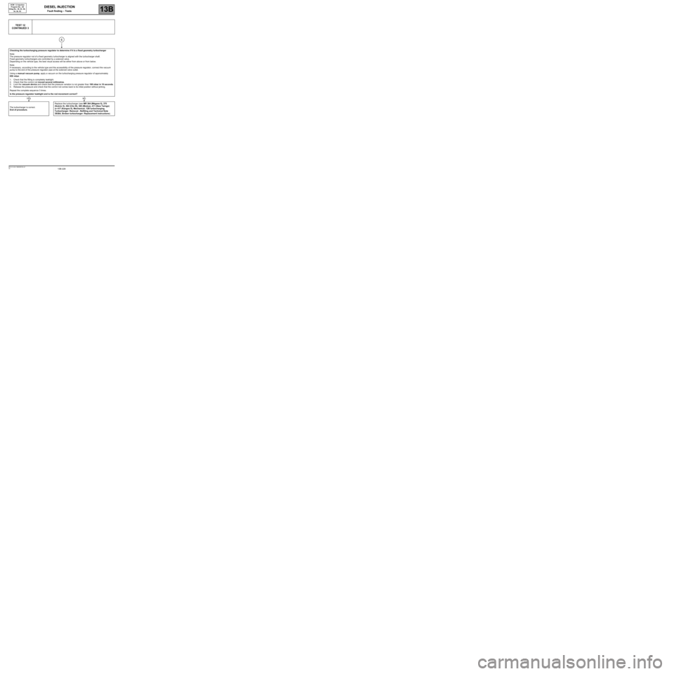
TEST 12
CONTINUED 3
Checking the turbocharging pressure regulator to determine if it is a fixed geometry turbocharger
Note:
The pressure regulator rod of a fixed geometry turbocharger is aligned with the turbocharger shaft.
Fixed geometry turbochargers are controlled by a solenoid valve.
Depending on the vehicle type, the best visual access will be either from above or from below.
Note:
If necessary, according to the vehicle type and the accessibility of the pressure regulator, connect the vacuum
pump to the end of the pressure regulator pipe at the solenoid valve outlet.
Using a manual vacuum pump, apply a vacuum on the turbocharging pressure regulator of approximately
650 mbar.
1. Check that the fitting is completely leaktight.
2. Check that the control rod moved several millimetres.
3. Lock the vacuum device and check that the pressure variation is not greater than 100 mbar in 10 seconds.
4. Release the pressure and check that the control rod comes back to its initial position without jerking.
Repeat the complete sequence 3 times.
Is the pressure regulator leaktight and is the rod movement correct?
The turbocharger is correct.
End of procedure.Replace the turbocharger (see MR 364 (Mégane II), 370
(Scénic II), 392 (Clio III), 385 (Modus), 411 (New Twingo)
or 417 (Kangoo II), Mechanical, 12B turbocharging,
Turbocharger: Removal - Refitting and Technical Note
3938A, Broken turbocharger: Replacement instructions).
C
YESNO
Page 239 of 269
13B-239V6 MR-413-X44-13B000$210.mif
DIESEL INJECTION
Fault finding – Fault finding charts13B
DCM 1.2 Injection
Program No.: 4D
Vdiag No.: 48, 4C, 50,
54, 58, 5C
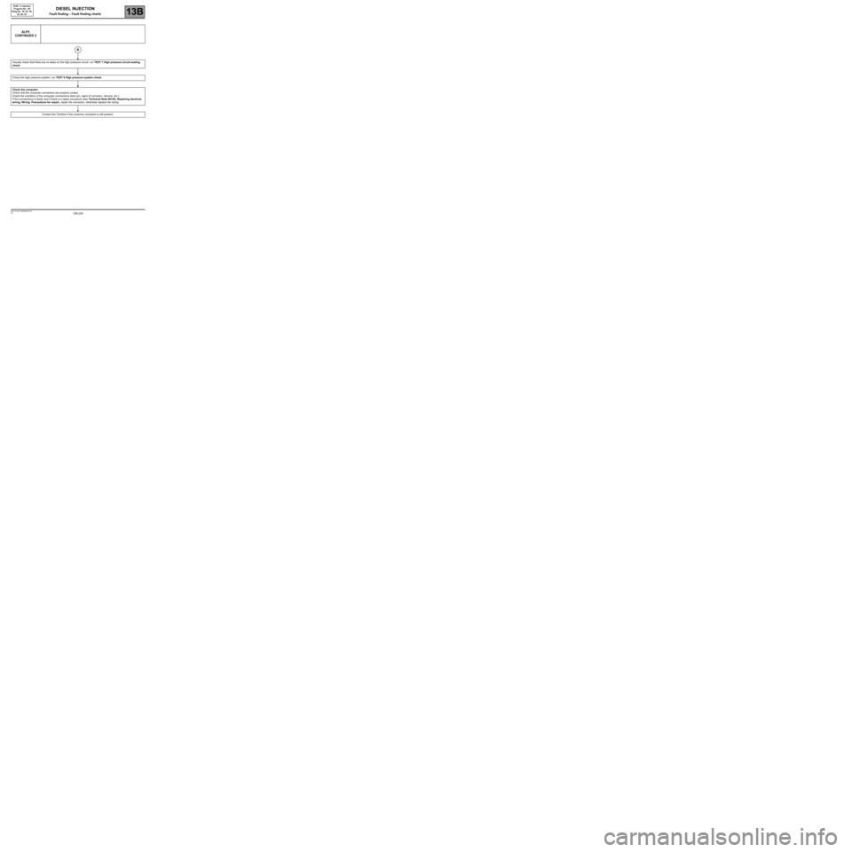
ALP2
CONTINUED 2
Visually check that there are no leaks on the high pressure circuit: run TEST 7 High pressure circuit sealing
check.
Check the high pressure system: run TEST 6 High pressure system check.
Check the computer:
Check that the computer connectors are properly locked.
Check the condition of the computer connections (bent pin, signs of corrosion, silicone, etc.).
If the connector(s) is faulty and if there is a repair procedure (see Technical Note 6015A, Repairing electrical
wiring, Wiring: Precautions for repair), repair the connector, otherwise replace the wiring.
Contact the Techline if the customer complaint is still present.
B
Page 241 of 269
13B-241V6 MR-413-X44-13B000$210.mif
DIESEL INJECTION
Fault finding – Fault finding charts13B
DCM 1.2 Injection
Program No.: 4D
Vdiag No.: 48, 4C, 50,
54, 58, 5C
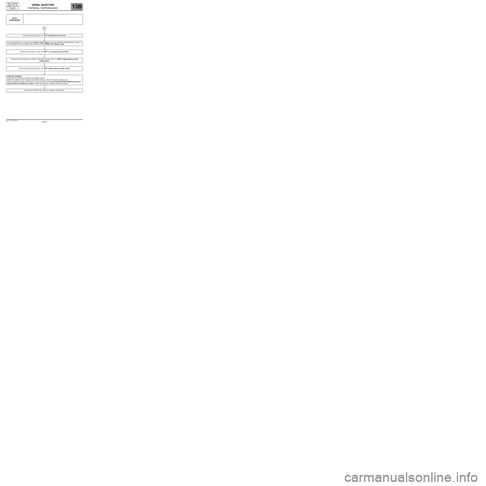
ALP3
CONTINUED
Check the electrical circuit: run TEST 2 Electrical circuit check.
Using the diagnostic tool, check that the injector codes (C2I) are correctly entered on the identification screen. If
not, configure the correct injector codes using command SC002 Enter injector codes.
Check the low pressure circuit: run TEST 1 Low pressure circuit check.
Visually check that there are no leaks on the high pressure circuit: run TEST 7 High pressure circuit
sealing check.
Check the high pressure system: run TEST 6 High pressure system check.
Check the computer:
Check that the computer connectors are properly locked.
Check the condition of the computer connections (bent pin, signs of corrosion, silicone, etc.).
If the connector(s) is faulty and if there is a repair procedure (see Technical Note 6015A, Repairing electrical
wiring, Wiring: Precautions for repair), repair the connector, otherwise replace the wiring.
Contact the Techline if the customer complaint is still present.
A
Page 243 of 269
13B-243V6 MR-413-X44-13B000$210.mif
DIESEL INJECTION
Fault finding – Fault finding charts13B
DCM 1.2 Injection
Program No.: 4D
Vdiag No.: 48, 4C, 50,
54, 58, 5C
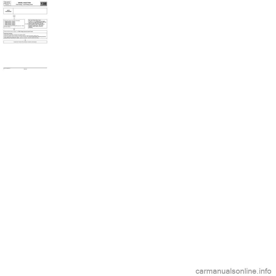
ALP4
CONTINUED
Control the injectors using the commands:
–AC005 Cylinder 1 injector,
–AC006 Cylinder 2 injector,
–AC007 Cylinder 3 injector,
–AC008 Cylinder 4 injector.
Can you hear the valve moving when you are 1 metre
from the vehicle?Run Test 9 Diesel filter check.
If test 9 is correct, replace only the faulty
injector(s) (see MR 364 (Mégane II), MR 370
(Scénic II), MR 385 (Modus), MR 392
(Clio III), MR 411 (New Twingo), MR 417
(Kangoo 2), Mechanical, 13B, Diesel
injection, Diesel injector: Removal -
Refitting).
Check the high pressure system: run TEST 6 High pressure system check.
Check the computer:
Check that the computer connectors are properly locked.
Check the condition of the computer connections (bent pin, signs of corrosion, silicone, etc.).
If the connector(s) is faulty and if there is a repair procedure (see Technical Note 6015A, Repairing electrical
wiring, Wiring: Precautions for repair), repair the connector, otherwise replace the wiring.
Contact the Techline if the customer complaint is still present.
A
NO
YES
Page 245 of 269
13B-245V6 MR-413-X44-13B000$210.mif
DIESEL INJECTION
Fault finding – Fault finding charts13B
DCM 1.2 Injection
Program No.: 4D
Vdiag No.: 48, 4C, 50,
54, 58, 5C
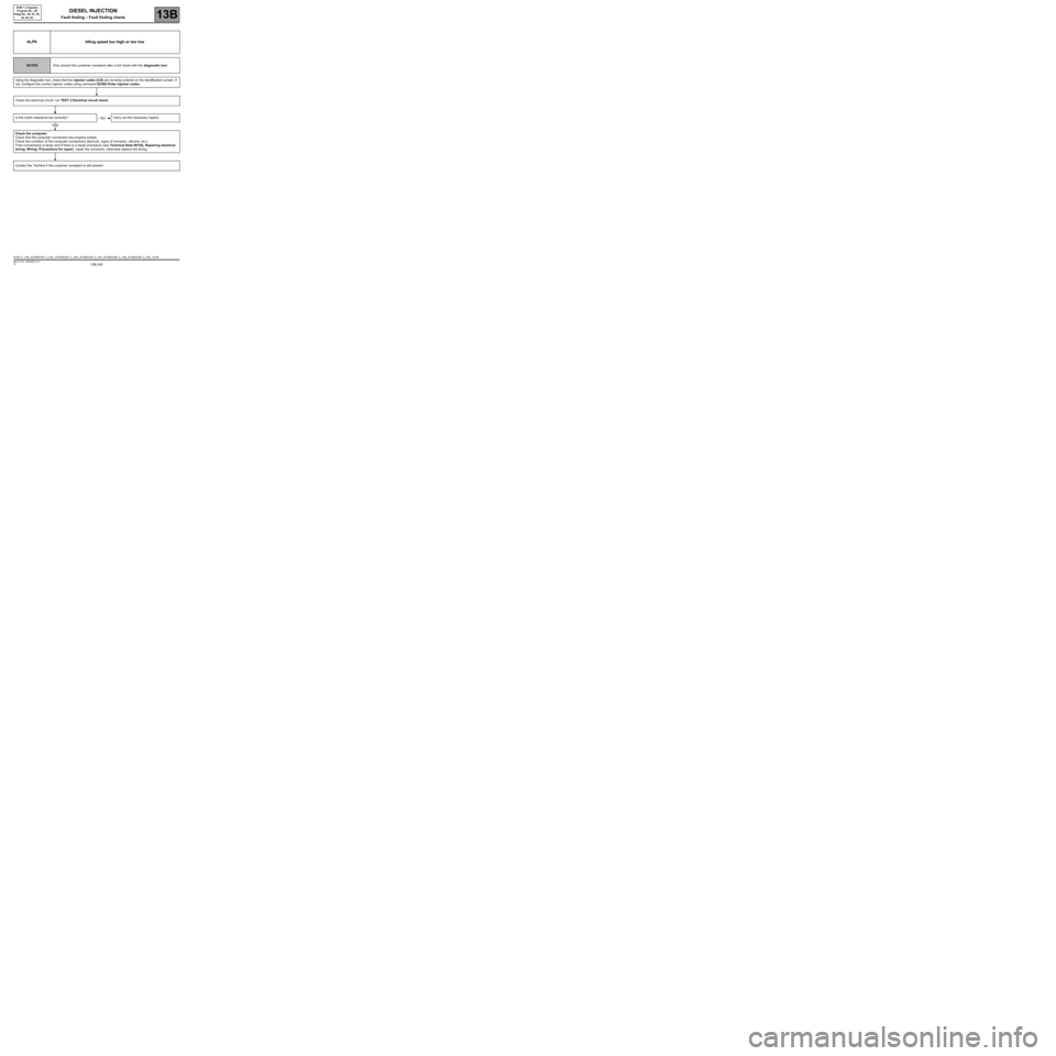
ALP6 Idling speed too high or too low
NOTESOnly consult this customer complaint after a full check with the diagnostic tool.
Using the diagnostic tool, check that the injector codes (C2I) are correctly entered on the identification screen. If
not, configure the correct injector codes using command SC002 Enter injector codes.
Check the electrical circuit: run TEST 2 Electrical circuit check.
Is the clutch clearance set correctly? Carry out the necessary repairs
Check the computer:
Check that the computer connectors are properly locked.
Check the condition of the computer connections (bent pin, signs of corrosion, silicone, etc.).
If the connector(s) is faulty and if there is a repair procedure (see Technical Note 6015A, Repairing electrical
wiring, Wiring: Precautions for repair), repair the connector, otherwise replace the wiring.
Contact the Techline if the customer complaint is still present.
NO
YES
DCM1.2_V48_ALP6/DCM1.2_V4C_ALP6/DCM1.2_V50_ALP6/DCM1.2_V54_ALP6/DCM1.2_V58_ALP6/DCM1.2_V5C_ALP6
Page 246 of 269
13B-246V6 MR-413-X44-13B000$210.mif
DIESEL INJECTION
Fault finding – Fault finding charts13B
DCM 1.2 Injection
Program No.: 4D
Vdiag No.: 48, 4C, 50,
54, 58, 5C
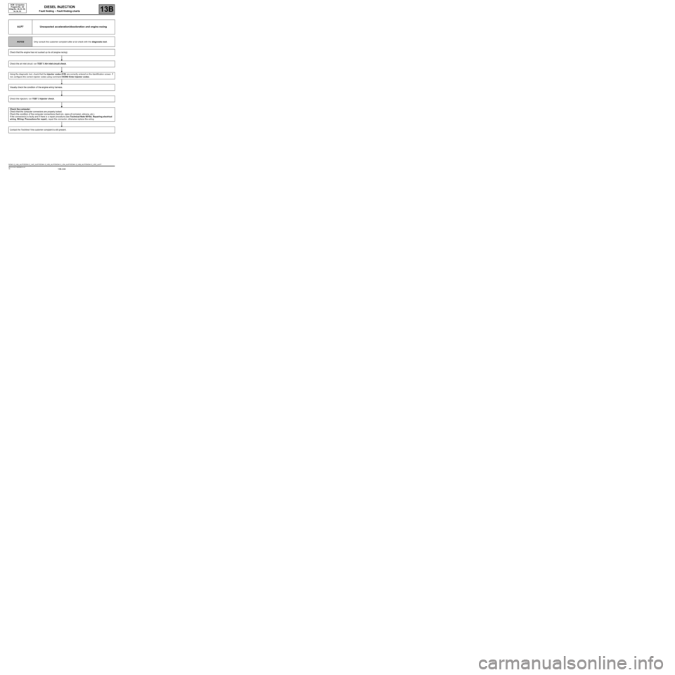
ALP7 Unexpected acceleration/deceleration and engine racing
NOTESOnly consult this customer complaint after a full check with the diagnostic tool.
Check that the engine has not sucked up its oil (engine racing).
Check the air inlet circuit: run TEST 5 Air inlet circuit check.
Using the diagnostic tool, check that the injector codes (C2I) are correctly entered on the identification screen. If
not, configure the correct injector codes using command SC002 Enter injector codes.
Visually check the condition of the engine wiring harness.
Check the injectors: run TEST 3 Injector check.
Check the computer:
Check that the computer connectors are properly locked.
Check the condition of the computer connections (bent pin, signs of corrosion, silicone, etc.).
If the connector(s) is faulty and if there is a repair procedure (see Technical Note 6015A, Repairing electrical
wiring, Wiring: Precautions for repair), repair the connector, otherwise replace the wiring.
Contact the Techline if the customer complaint is still present.
DCM1.2_V48_ALP7/DCM1.2_V4C_ALP7/DCM1.2_V50_ALP7/DCM1.2_V54_ALP7/DCM1.2_V58_ALP7/DCM1.2_V5C_ALP7
Page 248 of 269
13B-248V6 MR-413-X44-13B000$210.mif
DIESEL INJECTION
Fault finding – Fault finding charts13B
DCM 1.2 Injection
Program No.: 4D
Vdiag No.: 48, 4C, 50,
54, 58, 5C
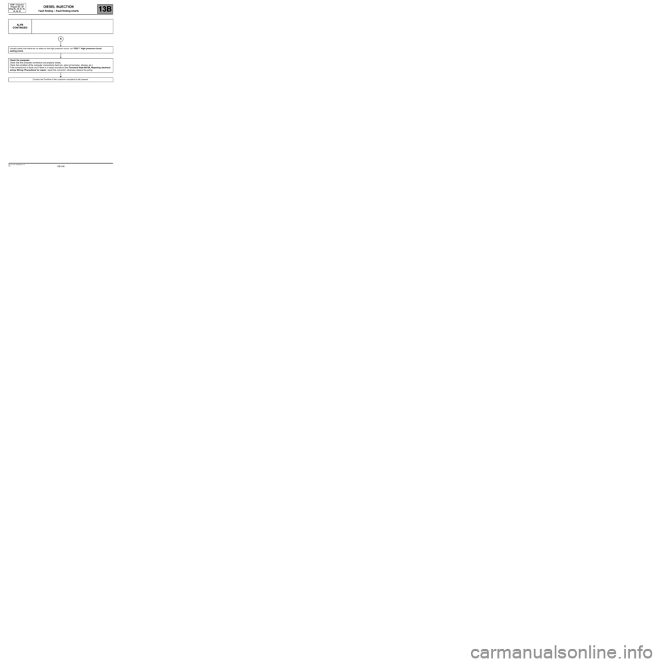
ALP8
CONTINUED
Visually check that there are no leaks on the high pressure circuit: run TEST 7 High pressure circuit
sealing check.
Check the computer:
Check that the computer connectors are properly locked.
Check the condition of the computer connections (bent pin, signs of corrosion, silicone, etc.).
If the connector(s) is faulty and if there is a repair procedure (see Technical Note 6015A, Repairing electrical
wiring, Wiring: Precautions for repair), repair the connector, otherwise replace the wiring.
Contact the Techline if the customer complaint is still present.
A
Page 250 of 269
13B-250V6 MR-413-X44-13B000$210.mif
DIESEL INJECTION
Fault finding – Fault finding charts13B
DCM 1.2 Injection
Program No.: 4D
Vdiag No.: 48, 4C, 50,
54, 58, 5C
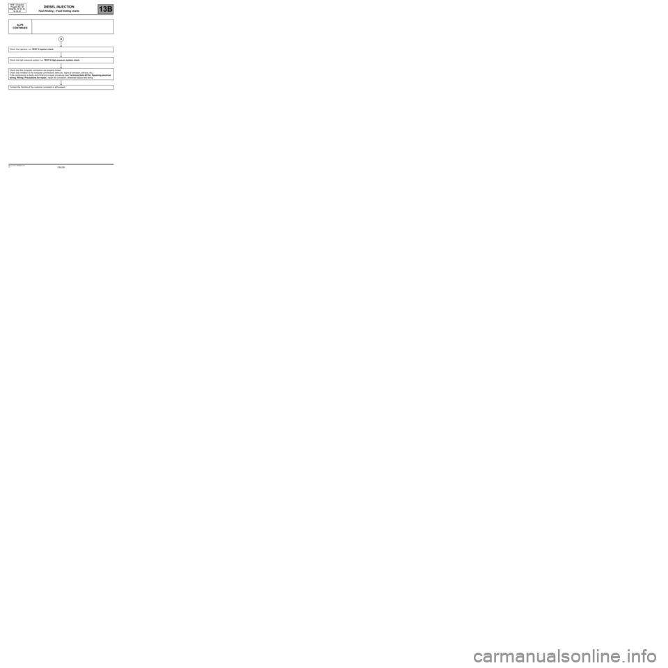
ALP9
CONTINUED
Check the injectors: run TEST 3 Injector check.
Check the high pressure system: run TEST 6 High pressure system check.
Check that the computer connectors are properly locked.
Check the condition of the computer connections (bent pin, signs of corrosion, silicone, etc.).
If the connector(s) is faulty and if there is a repair procedure (see Technical Note 6015A, Repairing electrical
wiring, Wiring: Precautions for repair), repair the connector, otherwise replace the wiring.
Contact the Techline if the customer complaint is still present.
A
Page 252 of 269
13B-252V6 MR-413-X44-13B000$210.mif
DIESEL INJECTION
Fault finding – Fault finding charts13B
DCM 1.2 Injection
Program No.: 4D
Vdiag No.: 48, 4C, 50,
54, 58, 5C
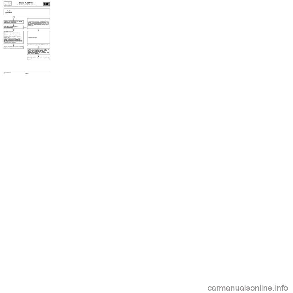
ALP10
CONTINUED
The vehicle has entered the "Flow capacity function"
program. This function is activated more easily when:
the external temperature is high, the fuel level in the
tank is at 1/4, the vehicle is laden and if the vehicle
speed is high. Check the high pressure pump: run TEST 6
High pressure system check.
Is the "Flow capacity function"
programming active?
Check the computer:
Check that the computer connectors are
properly locked.
Check the condition of the computer
connections (bent pin, signs of corrosion,
silicone, etc.).
If the connector(s) is faulty and if there is
a repair procedure (see Technical Note
6015A, Repairing electrical wiring, Wiring:
Precautions for repair), repair the connector,
otherwise replace the wiring.Check the diesel filter.
Has the diesel fuel filter reached its full mileage?
Contact the Techline if the customer complaint
is still present.
Replace the diesel filter (see MR 364 (Mégane II),
MR 370 (Scénic II), MR 385 (Modus), MR 392
(Clio III), MR 411 (New Twingo), MR 417
(Kangoo 2), Mechanical, 13A, Fuel mixture, Fuel
filter: Removal - Refitting).
Contact the Techline if the customer complaint is still
present.
A
YES
NO
YES